Transcription
Basic 3D Design
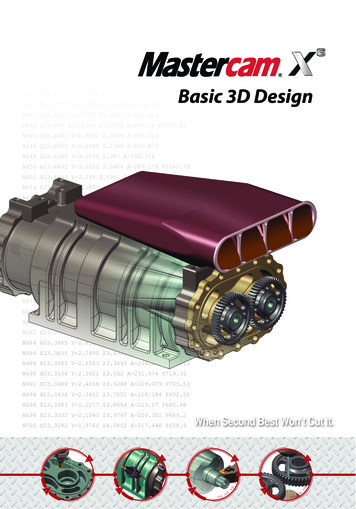
mastercam x getting started tutorialsMastercam X6Basic 3D DesignDecember 2011Be sure you have the latest information!Information might have been changed or added since this document waspublished. Contact your local Reseller for the latest information.
II MASTERCAM X6 BASIC 3D DESIGNMastercam X6 Basic 3D DesignDate: December 2011Copyright 2011 CNC Software, Inc.— All rights reserved.First Printing: December 2011Software: Mastercam X6TERMS OF USEUse of this document is subject to the Mastercam End User License Agreement.A copy of the Mastercam End User License Agreement is included with theMastercam product package of which this document is part. The MastercamEnd User License Agreement can also be found at:www.mastercam.com/legal/licenseagreement/
ContentsIntroduction . 1XTutorial Goals. 11. Geometry Translation . 5XXXXXXLesson Goals . 5Exercise 1: Setting Up the Part . 5Exercise 2: Creating the Drill Holes . 9Exercise 3: Creating the Pocket and Slot . 11Exercise 4: Creating the 3D Outside Perimeter . 18Exercise 5: Completing the Wireframe Model. 202. Dynamic Planes .XXXXLesson Goals . 27Exercise 1: Creating the Text Plane. 27Exercise 2: Creating the First Set of Letters . 34Exercise 3: Creating the Second Set of Letters . 383. Surface Creation .XXXXXXXX2743Lesson Goals . 44Exercise 1: Preparing for Surface Creation. 44Exercise 2: Creating the Top Flat Boundary Surface . 46Exercise 3: Creating the Bottom Flat Boundary Surface. 50Exercise 4: Creating the Middle Flat Boundary Surface . 54Exercise 5: Creating Ruled/Lofted Surfaces . 56Exercise 6: Creating Draft Surfaces. 62Exercise 7: Creating the Final Ruled/Lofted surface . 69
IV MASTERCAM X6 BASIC 3D DESIGN4. Creating the Tool Holder Part .XXXXXXX75Lesson Goals . 76Exercise 1: Drawing the Tool Holder, Part 1 . 76Exercise 2: Drawing the Tool Holder, Part 2 . 77Exercise 3: Drawing the Tool Holder, Part 3 . 82Exercise 4: Drawing the Tool Holder, Part 4 . 86Exercise 5: Drawing the Tool Holder, Part 5 . 91Exercise 6: Creating the Surface . 95Conclusion . 100XXMastercam Resources . 101Mastercam Documentation . 102
INTRODUCTIONAfter you have mastered drawing parts with Mastercam’s 2D functions, you are readyto move onto 3D part drawing. Drawing in 3D opens a whole new world of possibilities. In this tutorial, you learn many 3D drawing techniques as you construct theconnector and tool holder parts, shown in the following pictures.The tutorial titled Basic 2D Design covers 2D drawing with Mastercam. Beforeattempting this 3D tutorial, you must be familiar with the 2D techniques demonstrated in the 2D tutorial.Tutorial Goals Use construction planes in a 3D environment. Create 3D geometry from 2D parts using translation and offsetting. Define custom views using 3D Dynamic Planes. Use levels to organize 3D geometry. Generate 3D surfaces. Use construction lines as reference geometry. Use Mastercam’s Trim features to clean up your part.TIP: If you have trouble with an exercise, use Mastercam’s undo function ([Ctrl Z]) to return to a point where the part is correct and startagain from there. If undo does not help, go back to the beginning of theexercise, load the supplied file for that exercise, and start again.
2 TUTORIAL GOALSIMPORTANT: Screen colors in the tutorial pictures were modified toenhance image quality; they may not match your Mastercam settings orthe tutorial results. These color differences do not affect the lesson orthe exercise results.General Tutorial RequirementsAll Mastercam tutorials have the following general requirements: You must be comfortable using the Windows operating system. The tutorials cannot be used with Mastercam Demo/Home LearningEdition (HLE). The Demo/HLE file format (EMCX-6) is different fromMastercam (MCX-6), and basic Mastercam functions, such as fileconversions and posting, are unavailable. Each lesson in the tutorial builds on the mastery of preceding lesson’s skills.We recommend that you complete them in order. Focus Series and Exploring Series tutorials require, at minimum, a mastery ofthe basic Mastercam skills taught in the Getting Started Series modules. Ageneral knowledge of machining principals and practices is also required. You must have a seat of Mastercam X6 Design or higher to complete most ofthe tutorials in the Getting Started Series. The Basic 2D Machining module in the Getting Started Series requires, atminimum, a seat of Mill Entry or Router Entry. The Basic 3D Machining module in the Getting Started Series requires MillLevel 3 or Router Pro. Additional files may accompany a tutorial. Unless the tutorial providesspecific instructions on where to place these files, store them in a folder thatcan be accessed from the Mastercam workstation, either with the tutorial orin any location that you prefer. The Getting Started Series tutorials are available in an Adobe Flash compatible video format. Additional tutorial videos may also be available.Contact your local Mastercam Reseller for more information. You must install Adobe Flash Player to display tutorial videos. You candownload Adobe Flash Player from www.adobe.com.MASTERCAM X6 BASIC 3D DESIGN
INTRODUCTION 3 All Mastercam tutorials require you to configure Mastercam to work in adefault metric or English configuration. The tutorial provides instructionsfor loading the appropriate configuration file.MASTERCAM X6 BASIC 3D DESIGN
4 TUTORIAL GOALSMASTERCAM X6 BASIC 3D DESIGN
LESSON 1Geometry Translation1By translating existing 2D geometry, you can create a 3D part with minimal effort.This lesson takes the completed 2D part from the Basic 2D Design tutorial and showshow to use geometry translation to convert it into a full 3D part. The final 3D part isthen used as the source file for the Basic 3D Machining tutorial, the next book in thistutorial series.This lesson includes the following files, which you can use as needed: CONNECTOR START.MCX-6: The file you load to start this tutorial. CONNECTOR L01EX01.MCX-6: The part file after the completion of Lesson 1,Exercise 1. You can use this file to start Exercise 2. CONNECTOR L01EX02.MCX-6: The part file after the completion of Lesson 1,Exercise 2. You can use this file to start Exercise 3. CONNECTOR L01EX03.MCX-6: The part file after the completion of Lesson 1,Exercise 3. You can use this file to start Exercise 4. CONNECTOR L01EX04.MCX-6: The part file after the completion of Lesson 1,Exercise 4. You can use this file to start Exercise 5. CONNECTOR L01EX05.MCX-6: The part file after the completion of Lesson 1,Exercise 5. You can use this file to start Lesson 2, Exercise 1.Lesson Goals Set up the part for 2D to 3D conversion. Use translation to create new geometry. Define views for setting the Cplane. Toggle between 2D and 3D drawing modes.Exercise 1: Setting Up the PartIn this exercise, you prepare the 2D part for conversion to 3D. This process includespositioning the part on the screen, setting the construction plane, and creating anew level for the geometry you create in subsequent exercises.
6 SETTING UP THE PART1 Load the CONNECTOR START.MCX-6 part file, which is supplied with thistutorial.Note: If Mastercam warns you that you are changing units of measurement,click the message’s OK button to continue.2 From Mastercam’s menu bar, choose File, Save As, and save the part asCONNECTOR WORK.MCX-6.By saving the file under another name, you avoid accidentally overwritingthe original file.3 In the Gview menu on the statusbar, select Isometric (WCS).MASTERCAM X6 BASIC 3D DESIGN
GEOMETRY TRANSLATION 7TIP: You can also select a Gviewfrom Mastercam’s toolbars. Forexample, to select the Isometricview, click the Isometric (WCS)button in the Graphics Viewstoolbar.4 From the toolbar, choose Fit andUn-zoom .8.The part now displays at aconvenient position and size.5 In the WCS menu on the status bar,select View Manager.The View Manager dialog boxopens.6 In the View Manager dialog box,click where the FRONT rowintersects with the C column, andthen click OK.Mastercam sets the construction plane (Cplane) to the Front orientation.The changes you make to the part now are relative to the Front plane.7 On the status bar, click inside the Level drop-down box, type 4:3DGEOM,and then press [Enter].MASTERCAM X6 BASIC 3D DESIGN
8 SETTING UP THE PARTNote: Although the Level drop-down places spaces on both sides of thecolon, you do not need to type the spaces when selecting or creating a level.Mastercam creates a new level 4 and names it 3DGEOM. Geometry youcreate in the following steps will now go on the 3DGEOM level. You canmanage your file’s levels in Mastercam’s Level Manager (shown in thepicture below). For more information on levels, refer to Mastercam Help.MASTERCAM X6 BASIC 3D DESIGN
GEOMETRY TRANSLATION 98 Choose File, Save to save your workto disk.Exercise 2: Creating the Drill HolesThe part has four holes that must be drilled. In this exercise, you use translation tocreate copies of the four holes at their required depth. You can continue with the fileyou started in Exercise 1, or you can start this exercise by loadingCONNECTOR L01EX01.MCX-6. If you choose to load CONNECTOR L01EX01.MCX-6, besure to save it under a new name, so that you do not overwrite the original file.1 From Mastercam’s menu, selectXform, Translate.2 Select the four small circles, asshown.The order in which you select theholes is unimportant.MASTERCAM X6 BASIC 3D DESIGN
10 CREATING THE DRILL HOLES3 Click End Selection on the ribbonbar.Mastercam sets the circles as the currently selected geometry, which is thegeometry that gets translated in the following step.4 In the Translate dialog box, do thefollowing:a Select Copy.b Set Y to -30.c Click OK.Mastercam creates copies of theselected geometry, 30 mm down theY axis.5 On the toolbar, click Clear Colors.MASTERCAM X6 BASIC 3D DESIGN
GEOMETRY TRANSLATION 11Mastercam sets the new geometry to the default color. The following imageshows the part at this point.6 Choose File, Save to save your work.Exercise 3: Creating the Pocket and SlotThe connector part features a large pocketed area, as well as a wide slot at itsrounded end. In this exercise, you use translation and offsetting to create additionalgeometry for these features. You can continue with the file you worked on Exercise 2,or you can start this exercise by loading CONNECTOR L01EX02.MCX-6. If you chooseto load CONNECTOR L01EX02.MCX-6, be sure to save it under a new name, so thatyou do not overwrite the original file.MASTERCAM X6 BASIC 3D DESIGN
12 CREATING THE POCKET AND SLOTX Creating New Geometry for the Pocket1 From the MRU function bar(located on the right side ofMastercam’s window), select XformTranslate.The MRU toolbar provides aconvenient way to select functionsthat you have used recently in thecurrent Mastercam session.2 On the General Selection ribbonbar, set the selection mode toChain.You can now use the chainingfunction to select the geometry totranslate.3 Click the inner pocket, as shown in the following picture, and then click EndSelection on the ribbon bar.The Translate dialog box opens.MASTERCAM X6 BASIC 3D DESIGN
GEOMETRY TRANSLATION 134 In the Translate dialog box, do thefollowing:a Select Copy.b Set Y to -10.c Click OK.Mastercam creates copies of the selected geometry 10 mm down the Y axis,as shown in the following picture.MASTERCAM X6 BASIC 3D DESIGN
14 CREATING THE POCKET AND SLOT5 On the toolbar, click Clear Colors.Mastercam removes the colors usedto show the translation results.X Creating New Geometry for the Slot1 From the MRU Function Bar, selectXform Translate.2 Hold down [Shift], click the slot, asshown, and then choose EndSelection on the ribbon bar.Holding down [Shift] is anotherway to choose the chain selectionmode.3 In the Translate dialog box, do thefollowing:a Select Move.b Set Y to -10.c Click OK.MASTERCAM X6 BASIC 3D DESIGN
GEOMETRY TRANSLATION 15This time, Mastercam moves, ratherthan copies, the selected geometrydown the Y axis by 10 mm.4 On the status b
tutorial. Note: If Mastercam warns you that you are changing units of measurement, click the message’s OK button to continue. 2 From Mastercam’s menu bar, choose File, Save As, and save the part as CONNECTOR_WORK.MCX-6. By saving the file under another name, you avoid accidentally overwriting the original file. 3 In the Gview menu on the status bar, select Isometric (WCS). GEOMETRY .
