Transcription
Basic 2D Design
mastercam x getting started tutorialsBasic 2D DesignDecember 2011Be sure you have the latest information!Information might have been changed or added since this document waspublished. Contact your local Reseller for the latest information.
II BASIC 2D DESIGNMastercam X6 Basic 2D DesignDate: December 2011Copyright 2011 CNC Software, Inc.— All rights reserved.First Printing: December 2011Software: Mastercam X6TERMS OF USEUse of this document is subject to the Mastercam End User License Agreement.A copy of the Mastercam End User License Agreement is included with theMastercam product package of which this document is part. The MastercamEnd User License Agreement can also be found at:www.mastercam.com/legal/licenseagreement/
ContentsIntroduction . 1XTutorial Goals. 1General Tutorial Requirements . 21. Creating Lines and Arcs. 3XXXXXLesson Goals . 3Exercise 1: Drawing Vertical Lines. 3Exercise 2: Drawing Horizontal Lines . 7Exercise 3: Drawing Angled Lines and Circles . 8Exercise 4: Trimming the Outer Contour . 102. Creating Drill Holes .XXXLesson Goals . 13Exercise 1: Drawing the First Drill Hole . 13Exercise 2: Creating Additional Holes . 153. Modifying Geometry .XXXXXXX17Lesson Goals . 17Exercise 1: Offsetting the Outer Contour. 17Exercise 2: Adding Tangent Lines . 19Exercise 3: Trimming the Inner Contour . 21Exercise 4: Mirroring the Drill Holes. 22Exercise 5: Trimming the Mirrored Geometry . 24Exercise 6: Adding Fillets. 264. Adding a Slot.X1329Lesson Goals . 29
IV BASIC 2D DESIGNXXXXExercise 1: Starting the Slot. 29Exercise 2: Drawing Lines for the Slot. 30Exercise 3: Completing the Slot Geometry . 31Exercise 4: Changing the Slot’s Color and Level. 32Conclusion . 34XXMastercam Resources . 34Mastercam Documentation . 36Contact Us . 36
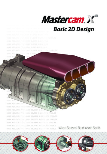
INTRODUCTIONMastercam provides many functions for creating and editing your part geometry,from simple 2D wireframe to complex 3D surface models. The Basic 2D Designmodule focuses on teaching you the 2D wireframe CAD tools used to draw thefollowing part.Tutorial Goals Draw basic geometry such as lines, arcs, and fillets. Set and change entity attributes. Select and chain geometry. Use AutoCursor and Visual Cues. Transform geometry. Trim geometry.IMPORTANT: Screen colors in the tutorial pictures were modified toenhance image quality; they may not match your Mastercam settings orthe tutorial results. These color differences do not affect the lesson orthe exercise results.
2 TUTORIAL GOALSGeneral Tutorial RequirementsAll Mastercam tutorials have the following general requirements: You must be comfortable using the Windows operating system. The tutorials cannot be used with Mastercam Demo/Home LearningEdition (HLE). The Demo/HLE file format (EMCX-6) is different fromMastercam (MCX-6), and basic Mastercam functions, such as fileconversions and posting, are unavailable. Each lesson in the tutorial builds on the mastery of preceding lesson’s skills.We recommend that you complete them in order. Focus Series and Exploring Series tutorials require, at minimum, a mastery ofthe basic Mastercam skills taught in the Getting Started Series modules. Ageneral knowledge of machining principals and practices is also required. You must have a seat of Mastercam X6 Design or higher to complete most ofthe tutorials in the Getting Started Series. The Basic 2D Machining module in the Getting Started Series requires, atminimum, a seat of Mill Entry or Router Entry. The Basic 3D Machining module in the Getting Started Series requires MillLevel 3 or Router Pro. Additional files may accompany a tutorial. Unless the tutorial providesspecific instructions on where to place these files, store them in a folder thatcan be accessed from the Mastercam workstation, either with the tutorial orin any location that you prefer. The Getting Started Series tutorials are available in an Adobe Flash compatible video format. Additional tutorial videos may also be available.Contact your local Mastercam Reseller for more information. You must install Adobe Flash Player to display tutorial videos. You candownload Adobe Flash Player from www.adobe.com. All Mastercam tutorials require you to configure Mastercam to work in adefault metric or English configuration. The tutorial provides instructionsfor loading the appropriate configuration file.BASIC 2D DESIGN
LESSON 1Creating Lines and Arcs1Lines and arcs are some of the most standard geometry used in 2D parts. This lessonintroduces you to some of Mastercam’s line and arc creation methods as you begindrawing the outer shape of the tutorial part.Lesson Goals Draw lines and arcs. Work with live entities. Trim geometry.Exercise 1: Drawing Vertical LinesIn this exercise, you start creating your part by drawing vertical construction lines.1 Start Mastercam using yourpreferred method: Double-click Mastercam’sdesktop icon.Or Launch Mastercam from theWindows Start menu.2 Select the default metric configuration file:a Select Settings, Configurationfrom Mastercam’s menu.
4 DRAWING VERTICAL LINESb Choose .\mcamxm.config Metric from the Current drop-down list.c Click OK.3 Press [F9] to display the XY axes in the graphics window.The coordinate axes show the origin and the part orientation to help youvisualize the part in 3D space.4 Choose Create, Line, Endpoint from the Mastercam menu.Mastercam displays the Line ribbon bar and prompts you to select the firstendpoint.BASIC 2D DESIGN
CREATING LINES AND ARCS 5Ribbon bars display based on what function you are using. Each ribbon barincludes options for the specific task you are doing. The Line ribbon bar hasoptions for creating a line by selecting two endpoints.TIP: You can click and drag the yellow prompt window to any position.5 Select the origin as your firstendpoint by moving your cursor tothe center of the graphics windowwhere the X and Y axes cross. Thecursor changes to an arrow with astar icon next to it.This is the AutoCursor, which letsyou quickly select and enter points.The Visual Cues icon attached tothe AutoCursor changes dependingwhat type of geometry you are near.This icon indicates that you are atthe origin.6 Click the origin and move yourcursor vertically along the Y axis.The Visual Cue changes to theHorizontal/Vertical icon. Thisconfirms that you are drawing avertical line.BASIC 2D DESIGN
6 DRAWING VERTICAL LINES7 Click anywhere along the Y axis toset a temporary line length. The linechanges to blue and is nowconsidered a live entity.Live entities can be modified bychanging values in the ribbon baruntil you exit the function, start anew function, begin to createanother entity, or click Apply. Onceyou begin another entity or exit thefunction, the entity becomes fixedand is no longer editable throughthe ribbon bar.8 On the Line ribbon bar, enter 50 forthe line length. This creates a 50mm vertical line.9 Click the Apply button on theribbon bar.The line is now fixed, but you stayin the Line function so you candraw more lines.10 Right-click anywhere in thegraphics window, and choose Fitfrom the pop-up menu. Thischanges the graphics view so allgeometry fits in the graphicswindow.BASIC 2D DESIGN
CREATING LINES AND ARCS 7TIP: The right-click menu has many functions that are used often. Youcan customize this menu to display the functions you use most bychoosing Settings, Customize and changing the settings on the Dropdowns/Right mouse button menu tab. For more information on how todo this, click the Help button on the Customize dialog box.Exercise 2: Drawing Horizontal LinesIn this exercise, you draw additional horizontal construction lines.1 Click the Length button on the Lineribbon bar.This locks the value, which is useful when you want to create multiple lineswith the same length. The field also turns red to indicate that it is locked.2 Click the Horizontal button. Thebutton remains pressed in. Thismeans that the next line you drawwill be horizontal.3 Move your cursor to the topendpoint of the first line. TheAutoCursor highlights the line andthe Visual Cue changes to indicatean endpoint.4 Click the endpoint. Because yourdirection and length are fixed, youonly have two options - to the left orright of the endpoint. Move yourcursor left and right to see the twopossible lines.BASIC 2D DESIGN
8 DRAWING ANGLED LINES AND CIRCLES5 Click to the right of the first line toset the new line position. Noticethat the new line is a live entity.6 Press [Enter] twice to complete theline.7 Click Length on the ribbon baragain to unlock the field. The nextline you draw will be a differentlength.8 Select the origin again as the firstendpoint and drag your cursor tothe right along the X axis. You arecreating another horizontal linebecause the Horizontal button isstill selected.Note: Make sure that the Visual Cue indicates the origin,not the lineendpoint.9 Click anywhere to set a temporarylength, and type 95 for the length inthe ribbon bar.10 Press [Enter] twice to complete theline.11 Right-click again in the graphicswindow and choose Fit to see all thelines.Exercise 3: Drawing Angled Lines and CirclesIn this exercise, you draw an angled line, and use the Create Line Parallel function todraw a parallel angled line. You also use the Create Circle Edge Point function todraw a circle using two points.BASIC 2D DESIGN
CREATING LINES AND ARCS 91 Deselect Horizontal. The next lineis at an angle.Press [Page Down] several times tozoom out from the part. This givesyou room to draw the angled line.2 Click the right endpoint of the 95mm line, and drag your cursor up tothe right at an angle.3 Click anywhere to create the live entity.4 Enter 50 for the line length and 30for the angle.5 Click Apply to complete the line.6 Click OK to close the Line ribbonbar.7 To draw a line that is parallel to theangled line, choose Create, Line,Parallel from the menu bar. Thisopens the Line Parallel ribbon bar.TIP: You can also access the menu bar using the keyboard. Press [Alt] todisplay the shortcut keys for each menu option. For example, you couldpress Alt, C, L, A to access the Create Line Parallel option.8 Select the angled line, and thenclick anywhere above the line.Mastercam creates a live parallelline entity.9 Enter 50 for the distance and clickOK.10 To add an arc to the end of the part, choose Create, Arc, Circle Edge Point.BASIC 2D DESIGN
10 TRIMMING THE OUTER CONTOUR11 Select the Two Point button on theCircle Edge Point ribbon bar.12 Select the upper endpoints of thetwo angled lines.13 Click OK to complete the arc.Exercise 4: Trimming the Outer ContourIn this exercise, you trim the construction geometry together to complete the part’souter contour.1 Choose Edit, Trim/Break, Trim/Break/Extend.2 Select the Trim 2 Entity button onthe ribbon bar.This function trims two entities totheir nearest intersection.3 Select the top angled line and thetop horizontal line.You should select the piece of theentity that you want to keep. In thisexample, you want to keep the leftside of the horizontal line and thetop of the angled line. The grayBASIC 2D DESIGN
CREATING LINES AND ARCS 11dotted line indicates the sectionthat will be trimmed.TIP: If the result does not look correct, choose Edit, Undo to remove thetrimming, and try selecting the geometry again.4 To trim the circle to the two angledlines, click the Divide/Deletebutton on the ribbon bar.This function divides entities based on the nearest intersection.5 Select the left-hand side of thecircle.6 Click OK to complete the trimming.Your part should look like thepicture at right.7 Choose File, Save to save thegeometry you have created. TheSave As dialog box displays becauseyou are saving the file for the firsttime.BASIC 2D DESIGN
12 TRIMMING THE OUTER CONTOUR8 Type OUTER CONTOUR.MCX-6 in the File Name field and click OK to save thefile.Note: For more information on saving files, refer to the Mastercam Help.Now that you have created the basic outline of
BASIC 2D DESIGN 1 Deselect Horizontal. The next line is at an angle. Press [Page Down] several times to zoom out from the part. This gives you room to draw the angled line. 2 Click the right endpoint of the 95 mm line, and drag your cursor up to the right at an angle. 3 Click anywhere to create the live entity. 4 Enter 50 for the line length and 30