Transcription
Mastercam 2017for SOLIDWORKSTutorial (Lathe)May 2016
Mastercam 2017 MCfSW Lathe TutorialDate: May 2016Copyright 2016 CNC Software, Inc.— All rights reserved.Software: Mastercam 2017 for SOLIDWORKSTERMS OF USEUse of this document is subject to the Mastercam End User License Agreement.The Mastercam End User License Agreement can be found nseAgreement.aspxBe sure youhave the latestinformation!Information might have been changed or added since this document waspublished. The latest version of this document is installed with Mastercam forSOLIDWORKS or can be obtained from your local Reseller. A ReadMe file(ReadMe.pdf)—installed with each release—includes the latest informationabout Mastercam for SOLIDWORKS features and enhancements.
iiiContentsIntroduction . 5 Tutorial Goals. 6General Tutorial Requirements . 61. General Setup. 9 Lesson Goals . 9Getting Ready to Work . 9Exercise 1: Loading a Machine Definition . 12Exercise 2: Creating a Work Coordinate System (WCS) . 15Lathe Coordinates. 15Exercise 3: Setting Up the Stock in the Main Spindle . 19Exercise 4: Defining the Chuck Jaws. 222. Facing, Roughing, and Finishing the Outer Diameter . Lesson Goals . 27Exercise 1: Facing the Part . 27Exercise 2: Roughing the Outer Diameter. 31Exercise 3: Finishing . 39Exercise 4: Backplotting the Toolpaths . 423. Adding Grooves and Threads. 2747Lesson Goals . 47Exercise 1: Grooving on the Outer Diameter: Multiple Chains . 47Exercise 2: Grooving on the Outer Diameter: Rough Pass Only. 54Exercise 3: Finishing with Plunge Cuts . 56Exercise 4: Adding a Thread Toolpath. 62Exercise 5: Verifying the Toolpaths . 68
iv MASTERCAM 2017 FOR SOLIDWORKS4. C-Axis Drilling Operations. Lesson Goals . 73Exercise 1: Adding a New Toolpath Group . 73Exercise 2: Creating a C-Axis Drill Operation. 74Exercise 3: Copying the Drilling Operation. 81Exercise 4: Modifying the Drilling Parameters. 825. Cutoff and Stock Flip. 99Lesson Goals . 99Exercise 1: Creating New Tools in the Lathe Tool Manager . 99Exercise 2: Facing the Back of the Part. 107Exercise 3: Drilling the First Inner Diameter . 108Exercise 4: Drilling the Second Inner Diameter. 111Exercise 5: Roughing and Finishing the Third Inner Diameter. 114Exercise 6: Adding an ID Thread . 122Exercise 7: Refining Your Verification Results . 1257. Post Output. 87Lesson Goals . 87Exercise 1: Cutting Off the Part . 87Exercise 2: Programming a Stock Flip. 916. Machining the Inner Diameter . 73131Lesson Goals . 131Exercise 1: Renumbering Tools . 131Exercise 2: Posting. 133Conclusion . 134 Mastercam for SOLIDWORKS Resources . 134Mastercam for SOLIDWORKS Documentation . 135Contact Us . 135
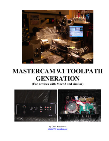
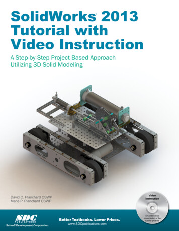
IntroductionMastercam for SOLIDWORKS Lathe deliverscomprehensive turning software withpowerful toolpaths and techniques. In thistutorial, you create general turning, milling(c-axis), and miscellaneous operations toprogram the interior core of a hose nozzle inMastercam 2017 for SOLIDWORKS. The partrequires basic lathe operations such asfacing, roughing, and finishing as well asgrooving and threading toolpaths.Starting with Lesson 2, a blueprint at thebeginning of each lesson provides thenecessary dimensions you need to createthe toolpaths. Within the parts folderthat is delivered with this tutorial, youwill find the original SOLIDWORKS partused in the tutorial. Nozzle - 2W.SLDPRTFor your reference, the folder also provides a sample of the part after each lesson: Hose Nozzle - Inner Core - L1.SLDPRT Hose Nozzle - Inner Core - L2.SLDPRT Hose Nozzle - Inner Core - L3.SLDPRT Hose Nozzle - Inner Core - L4.SLDPRT Hose Nozzle - Inner Core - L5.SLDPRT Hose Nozzle - Inner Core - L6.SLDPRT Hose Nozzle - Inner Core - L7.SLDPRTPlace these files (extracted from MCfSW Lathe Getting Started-2017.zip)anywhere that is convenient on your system, but be sure to also keep unmodifiedcopies.Although the illustrations in this tutorial show the SOLIDWORKS 2016 user interface,we provide SOLIDWORKS 2015 part files.
6 MASTERCAM 2017 FOR SOLIDWORKS / IntroductionMastercam for SOLIDWORKS is a comprehensive CAD/CAM software program, withsolutions for a wide array of machining applications. While this tutorial requires only abasic familiarity with Mastercam for SOLIDWORKS, its intention is to provide you withan introduction to the Lathe product. Use the resources listed at the end of this tutorialto explore and learn more about other features and functions in Lathe and inMastercam for SOLIDWORKS.Tutorial Goals Set up the job by creating a stock model and fixtures. Move the solid model to its machine orientation and create any necessary 2Dgeometry. Create and edit tools as required by the part operations and dimensions.NOTE: The tool numbers called out in this tutorial are the defaults listed inthe default library: Lathe mm.Tooldb. Your tools may have different toolnumbers. Program operations to work on a part’s inner and outer diameter. Use Mastercam for SOLIDWORKS’s verification tools and posting to checkyour work.Estimated time to complete this tutorial: 5 hoursGeneral Tutorial RequirementsAll Mastercam for SOLIDWORKS tutorials have the following general requirements: You must be comfortable using the Windows operating system. You must have a seat of SOLIDWORKS 2015 or higher to complete thistutorial. Each lesson in the tutorial builds on the mastery of preceding lesson’s skills.We recommend that you complete them in order. Additional files may accompany a tutorial. Unless the tutorial provides specificinstructions on where to place these files, store them in a folder that can beaccessed from the Mastercam for SOLIDWORKS workstation, either with thetutorial or in any location that you prefer.MCFSW LATHE TUTORIAL
TUTORIAL GOALS 7 You will need an internet connection to view videos that are referenced in thetutorials. All videos can be found on our YouTube SW LATHE TUTORIAL
8 MASTERCAM 2017 FOR SOLIDWORKS / IntroductionMCFSW LATHE TUTORIAL
LESSON 11General SetupBefore generating toolpaths for the part, you must prepare Mastercam for SOLIDWORKS and the part file. This preparation includes such tasks as selecting a machinedefinition and defining the stock.Lesson Goals Open and orient the part. Select a machine. Define stock boundaries. Add chuck jaws.Getting Ready to WorkThis tutorial includes the files you need to complete the exercises. You can find thesefiles in the tutorial’s Parts folder. Place these files on your system wherever convenient,but be sure to keep an unmodified set. In preparation for this tutorial, verify that theMastercam 2017 for SOLIDWORKS add-in is loaded properly into SOLIDWORKS. Thefollowing procedure leads you through this process.
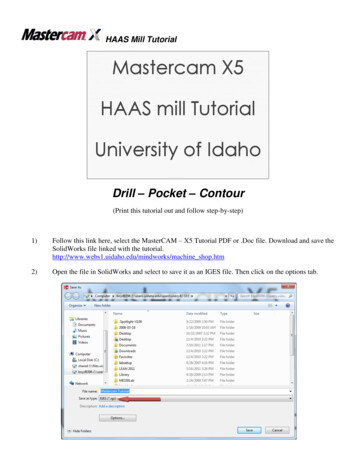
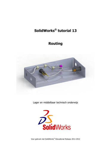
10 MASTERCAM 2017 FOR SOLIDWORKS / General Setup1 Start SOLIDWORKS.IMPORTANT: You must have SOLIDWORKS 2015 or higher to completethis tutorial.2 From the SOLIDWORKS menu bar,click the drop-down arrow next tothe Options icon, and select AddIns.The Add-Ins dialog box displays.3 Find Mastercam 2017 forSOLIDWORKS in the Active Add-Inslist, and then do the following:a To load the Mastercam 2017 forSOLIDWORKS add-in for thecurrent session, select thecheckbox to the left of theMastercam 2017 forSOLIDWORKS entry.b To load the Mastercam 2017 forSOLIDWORKS add-in at everySOLIDWORKS start-up, select thecheckbox to the right of theMastercam 2017 forSOLIDWORKS entry.c Click OK to close the dialog box.MCFSW LATHE TUTORIAL
GETTING READY TO WORK11After a few moments the add-inloads and the Mastercam 2017 InfoPane displays on the right-side ofthe graphics window, and theMastercam 2017 menu becomesavailable under the Tools menu. Enable Backplot in Mastercam SimulatorThis tutorial takes advantage of features in the Backplot mode available inMastercam Simulator. Mastercam 2017 for SOLIDWORKS allows you to openeither this version of Backplot or an earlier version (Classic Backplot) when youaccess it via the Backplot button in the Toolpaths Manager. Use the followingprocedure to ensure that Mastercam for SOLIDWORKS defaults to the morerecent application.1 From your Windows Start menu,select All Programs, Mastercam2017 for SOLIDWORKS, Utilities,Advanced Configuration.2 Select Backplot.3 If necessary, choose the option to disable Classic Backplot from the drop-down menu.4 Select OK.MCFSW LATHE TUTORIAL
12 MASTERCAM 2017 FOR SOLIDWORKS / General SetupExercise 1: Loading a Machine DefinitionMastercam for SOLIDWORKS automatically creates a machine group for each machineyou select from the machine selection menu item. To see how machine selectionworks, complete the following exercise.1 Open the part file, Nozzle-2W.SLDPRT, which was provided with this tutorial.2 Save the part as Hose Nozzle - Inner Core.SLDPRT.Saving the part under a new name helps prevent you from accidentallymodifying the original.3 In the SOLIDWORKSFeatureManager, click theMastercam Toolpaths Manager tabto display the Toolpaths Manager.By default, Mastercam forSOLIDWORKS loads a Mill machinedefinition when you open a new file.MCFSW LATHE TUTORIAL
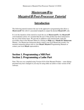
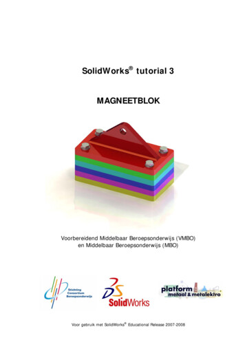
LOADING A MACHINE DEFINITION 13Since this tutorial requires a Lathe machine, you will load the default Lathemachine definition.4 Select Tools, Mastercam2017, Lathe Machines, Default.The menu lists all available machine definitions. Normally, you would selectthe machine on which you plan to cut the part from the list displayed here.The gnomon changes to displayLathe DZ coordinates.The Lathe coordinate system isdiscussed in Exercise 2.MCFSW LATHE TUTORIAL
14 MASTERCAM 2017 FOR SOLIDWORKS / General Setup5 In the Toolpaths Manager, right- click on Machine Group-1 (the Mill machinegroup), and select Groups, Delete.A Mill machine group is not necessary for this tutorial.TIPS: You can change the default startup product to Lathe from the SystemConfiguration dialog box. See Mastercam for SOLIDWORKS Help formore information. To customize the Machine Selection lists, choose a machine type fromthe Mastercam2017 menu, and select Manage List. For more informationon the dialog box that displays, click the dialog box’s Help button. Rename the Machine GroupMachine groups store complete jobs for a specific machine. For example, if sometoolpaths will be cut on a lathe, and other toolpaths on a mill, you can simplycreate a second machine group. Each machine group can store its own job setupinformation and tools, and use a different set of toolpath defaults. The toolpathsfrom each group will post to separate NC files.Mastercam for SOLIDWORKS lets you create as many machine groups as youneed to organize your work.1 Right-click the machine group, and select Groups, Rename from the pop-upmenu.MCFSW LATHE TUTORIAL
CREATING A WORK COORDINATE SYSTEM (WCS) 15Mastercam for SOLIDWORKS highlights the current group name.2 Type a new machine group name.The machine group name can beanything you want, but it’s best tochoose a name that describes themachine and its operations.3 Select File, Save to save the file.Exercise 2: Creating a
In preparation for this tutorial, verify that the Mastercam 2017 for SOLIDWORKS add-in is loaded properly into SOLIDWORKS. The following procedure leads you through this process. 10 MASTERCAM 2017 FOR SOLIDWORKS / General Setup MCFSW LATHE TUTORIAL 1 Start SOLIDWORKS. IMPORTANT: You must have SOLIDWORKS 2015 or higher to complete this tutorial. 2 From the