Transcription
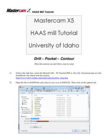
HAAS Mill TutorialDrill – Pocket – Contour(Print this tutorial out and follow step-by-step)1)Follow this link here, select the MasterCAM – X5 Tutorial PDF or .Doc file. Download and save theSolidWorks file linked with the hine shop.htm2)Open the file in SolidWorks and select to save it as an IGES file. Then click on the options tab.
3)In the Options menu select IGES 5.3 and make sure that the IGES wireframe (3D curves) is enabled.If it is not then select the check box next to it.4)Open MasterCam X5.5)Click the file open . Then select “all files” from the drop down menu files of type and select thedesired file in this case the one that was just saved as an IGES file.6)Once the part loads click Fit7)To align the part to a usable orientation we will use the view tools, click theright planeto see the entire work. piece.to rotate the view.8)From here select the Xform rotateto rotate the part to the correctorientation, so that the part will match the axis of the HAAS mill so it can bemachined.9)Click outside of the part and Drag a box about the entire part then click again,all selected parts will turn yellow, follow this by pressing return to bring upthe transform menu, shown on the right. Only entities that are completely inthe selection box will be selected.
10)For this piece, rotate the part 90 degrees so as to bring the part to the correct machining plane. Alsomake sure “Move” is selected and not “Copy”.11)For a more visual representation of the origin and the HAAS axis press F9. To make sure that thepart is oriented properly click on the Top Viewwould see it on the bed of the mill.12). In this view the part should be oriented as youIn the case that your part is not at the origin (this part is oriented correctly but this step can be usedas a reference for future parts), again select the entire part, this time clicking Xform Translate,select the “Move” option. Next, click on the 1in the translate command box.Select the corner you want as the origin and then select the origin either by mouse click or the X,Y,Zcoord. box found with the tool bars. Once selected press the check boxthis will move theselected corner of your part to the origin.13)Before starting the tool paths, define the machine that you will be using. To do this click MachineType (found on the top toolbar), Mill, and select the HAAS CNC Mill. If the HAAS CNC Mill is notan option select Manage List, HAAS Mill, and then Add to add it to the list of machines. This allowsthe final code to be posted to the HAAS CNC Mill.14)Under the tool paths tab on the left in the design tree, you will notice that some new items haveappeared. Expand the properties menu and click on stock setup.15)Input the X, Y, & Z dimensions of the stock and set the origin, the origin and the display are asshown in the following picture.
16)Click on the left-most corner on the top face of the red box to define your stock origin. Manuallyinput the actual values, making sure that “Display” box is checked and that “Wire Frame” isselected.17)Clickto return to the workspace. The plate should now be surrounded by a red dashed box,which shows the raw stock size that will be used the machine the piece from. If the box is notcentered about the part then the origin of the stock or part is off.18)Before continuing the part should be savedsame location as the tutorial).19)Next the corners of the plate will be rounded off. In MasterCAM modification can be made easilyto your personal folder or other media (NOT thewithout having to open SolidWorks. Click on the drop down menu arrows on the right ofselect Fillet Entities. Manually set the values for the fillets as shown below:,20)Select the two lines which form the lower left corner and Mastercam will create the fillet. Repeat thisstep for the other three corners of the plate. Make sure that the fillets are all on the top plane of thepart or else the tool path will not chain correctly.21)Click on the drop down menu arrow on the right of, select Create Circle Center Point. Thenclick on the center point of a fillet then the check box to make the circle, followed by manuallysetting the values for the hole as shown below (values can be either as radius or diameter).Repeat this step for each of the center points of the fillets. The Circle sizes cannot be changed, oncemade, they are set, so if a non-desired size is made simply delete and remake it.22)Right click the design tree on the left side of the screen, select Mill Toolpaths then select Drill fromthe drop menu. Select the center points of the four bolt holes to be drilled.
Click the check button. For larger holes a center drill operation maybe needed prior to this.23)Click on the “select library tool ” and select the ¼’’ Drill. Change the tool # and head # to “1”Change the spindle speed to 2500 and the feed rate to 1 (found from drill chart).24)Now select the Peck Drill in the Cut Parameters menu. Under Linking Parameters set the depth to-0.35. Also set the retract to Absolute. Click the check mark. You will notice that the tool pathis now shown on the workspace and there is now the tool path and properties in the design tree onthe left tab “Tool paths”. Note: A center drill operation should be used for most drilling operations.For drilling on the Bridgeport CNC Mill, the retract height must be included in the depth that youwould like to drill to. Otherwise, the holes will be too shallow!25)There are two methods available to visualize the newly created toolpath. UnderToolpath Group 1 in the design tree, select Toolpath 1. Now click on the backplotbutton in the toolbar directly above the design tree. A new toolbar will appearwith VCR-like controls. Before pressing play, rotate the view to the desiredorientation. Press the play button to animate the toolpath.26)You can also view the process in a more realistic view by pressing the verifybutton. Likewise, animation parameters become available when using thisfunction. When you press play, you should see the mill drilling 4 small holes in
the stock you have specified. It should look just as you would expect it to if you were actuallymachining the part. The computer simulates the part being cut. Toward the bottom of the dialog boxyou can adjust the cutting speed. A yellow surface indicates a cut. A red surfaceindicates a collision. If red appears by the end of the simulation, your tool settings need to beadjusted. Select green check markto exit the Verify dialog box.27)Right-click the red arrow in the design tree to add another toolpath, select Mill Toolpaths andContour. Change inside to outside. Now select the left edge below the center line, it iscrucial that you select the chains properly as it will determine where the chain starts and ends for thetool path. You may have to select each line segment sequentially until it forms a chain, oncesatisfied press.28)The toolpath parameter window should appear. Specify ½” Endmill from tool library as donepreviously. Change the tool # and head # to 2. Change the feed rate to 4, the spindle speed to 1250,retract rate to 10, and the plunge rate to 1. In the Coolant menu turn on the Flood option. Click onthe Linking Parameters tab and change the depth to -0.26.29)Introduction to lettering, right-click on the design tree to add another toolpath, click Mill Toolpathsand click Pocket. Select the Area option and click inside of the letters to select and click. Tostart a new chain, you must click the End Chain buttondifferent chains are not connected.first. This tells Mastercam that the30)In the same way you have previously selected tools, select the 1/32 flat endmill. Change the tool #and the head # to 3. Change the feed rate to 5, the spindle speed to 4000, retract rate to 10, and theplunge rate to 1. Under the Linking Parameters tab, change the depth to -0.003. Click the RoughingMenu and choose parallel spiral for the cutting method. Click the.31)Your CNC code should now be finished. To verify the operations:
32)a. Clickto select all operations.b. Clickto regenerate all tool paths.c. Clickto verify operations.For posting the code that you have just written, go tohttp://www.webs1.uidaho.edu/mindworks/machine shop.htm and select the tutorial on posting the“G1” code to the HAAS mill.Your verified toolpaths should look like:Additional: For pocketing and contours sometimes multiple passes are needed for roughing before the finishpass. If the depth to be milled is more than 50% of the tool diameter then a roughing depth should be set.Example: Click the depth cuts button and change the maximum roughing step to 0.2. This will force themachine to do two depth passes for each pocket while being less than the 0.25 maximum for this endmill. Adepth finishing pass will not be necessary since the pocket goes through the stock entirely. Select the break thrubutton and change the value to 0.025. Click machine finish passes only at final depth.
same location as the tutorial). 19) Next the corners of the plate will be rounded off. In MasterCAM modification can be made easily without having to open SolidWorks. Click on the drop down menu arrows on the right of , select Fillet Entities. Manually set the values for the fillets as shown below: