Transcription
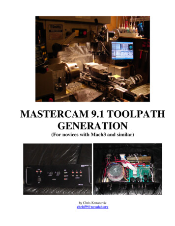
MASTERCAM 9.1 TOOLPATHGENERATION(For novices with Mach3 and similar)by Chris Krstanovicchris59@novalab.org
IntroductionI recently finished converting my Smithy 1220 LTD to a CNC. I designed all the hardware from scratch,as everything that I found available seemed inadequate for my needs. I design electronics for a living, so itwas no big deal to me. However, I was totally unprepared for the world of CAM software. I use Mach3,and although it comes with some nice wizards, they are a far cry from my needs. I finally selectedMasterCAM 9.1, as it is available to me, and is (despite its DOS-like appearance) an extremely capablesystem (as you would expect for 20,000 , I think).For those who have access to it, this article is a short introduction to how to use MasterCAM 9.x togenerate a workable G-code for the Mill. It mainly outlines the design process, and provides enoughbackground to allow the reader to experiment and learn its operation. I placed an emphasis on smallerretrofit machines running controllers such as Mach3.If you take this path, I recommend you take the on-line training course at www.streamingteacher.com . Itwill set you back 240, but is truly excellent, and worth the money and the time. You can get couple offree sample lessons at:http://www.streamingteacher.com/c1 mcam mastercam/mcam mc samples.aspxI also highly recommend reading: Learning MasterCAM Mill Step by Step. (ISBN 1-886552-01-0)
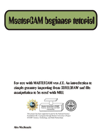
MASERCAM 9.1 TOOLPATH GENERATION1. PREPARE MODEL GEOMETRYIMPORT Solid Edge MODEL (If applicable)Note: When creating the model in Solid Edge it is handy to also prepare the .STL for thelater verify.Use Parasolid models if possible when dealingwith solids and surfaces. Using the AutoCad.dwg or dxf will work also, but this primer isprimarily targeting solid modeling CADsystems (this is what I use). After the modelimport, the process is the same for all models.Go to:FILE/CONVERTERS/PARASOLID/READNavigate to the file and select to open. At theprompt box (may take a while to get sometimesfor big models), ensure that edge curves areselected and select either solids or surfaces,depending what will be needed. Note: wire-frame is usually enough for 2 1/2D.SEPARATE SOLIDS / SURFACES / WIRESAfter the import, everything will be on level 1. To makethings easier it is advantageous to separate the features. Inlevels, select active level to be the one where the solid issupposed to go. From main menu select SCREEN/CHGLEVELS. Use settings as shown and click OK. Hover themouse over the solid (or surface), and click once, then clickBACKUP (or ESC)/DONE. When checking LEVELS, therewill now be one entry in solids (or one or more in surfaces).
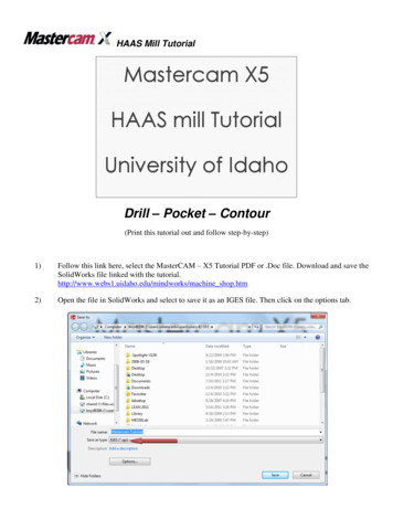
ADD FEATURES TO MODEL:It may be necessary to add points etc, to make certain operations easier to define. For example, ifthe corners were chamfered, it would be handy to have a point when translating model to origin.RE-POSITION THE MODEL IN CARTESIAN SPACE (optional):This can be done by either moving the model, or using the offsets. I prefer to move the entiremodel.Make sure that all the features are visible (LEVELS). From main menu useXFORM/TRANSLATE/ALL/ENTITIES/DONEThe next menu will let you chose the translation method. I mostly use Rectang and Between ptsdepending on what is needed.If the model needs rotating use:XFORM/ROTATE/ALL/ENTITIES/DONEAnd then select about what point it is to be rotated, and the method of rotation. Make sure thatcorrect construction plane is selected, so the rotation will be in appropriate plane.Now the model is imported, and positioned. Save the file in MC9 format.2. JOB-SETUP:This is where the stock, material, and optionallytools are selected. Start by changing the activelevel to the one designated for the stock. ThenfromthemainmenuselectTOOLPATHS/JOB SETUP.Select“Bounding Box” to define the stock size. Selectmaximum RPMs, feed Calc, Material, and getthe tools from the library. It is OK to selectmultiple tools at once. Although this can bedone later during the operation creations, this isa good place to get what will be needed, so thethought flow is not disturbed later.
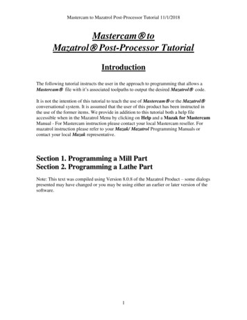
3. GENERATE TOOL-PATHSWhen working with wire-frame, turn off the solid in LEVELS. FromToolpath menu select the operation type required. For example to dothe Contouring: CONTOUR/CHAIN. Then, select “options”.àEnsure that plane mask is set. If the model is imported, and thelines are not fully touching, “Chaining tolerance” can be changedto, say, 0.005”. Set the chaining options as needed, but what isshown in the picture is quite typical. Click OK, and then proceedto select the chain – partial or otherwise.When finished press “done” and the parameters dialog will open.Select the tool, feed, etc. parameters, and then setup the contourparameters. It is important to set the tool change location (HomePositions) for every tool change. If not, your retro may fly pastthe limit switches and screw everything up. When done, clickOK, and the dialogs will disappear, and the tool-paths willbecome visible around the model.Select other operations as required, and when done proceed toverify and post modules.
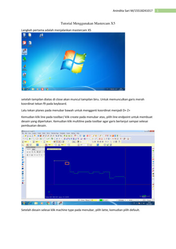
4. TEST&VERIFYTesting and verification of individual operations as well asof the whole process is done from the Operations Managermenu (TOOLPATHS/OPERATIONS or ctrl O”). This istruly the heart of the MasterCAM.This is an interactive process, through which operations aretested and fine-tuned during the process development.Right clicking on the Parameters opens up individualparameter screens. The tool can be examined and modifiedalso.“Backplot” allows the selected operation(s) to be singlestepped, or just run. The time estimate is also obtainedhere.Right clicking on blank area brings up many more options,and it is possible to add more operations right from there.Another powerful feature is the ability to drag and re-orderoperations, as well as to cut and paste them. In this way it ispossible to make a copy of a roughing operation, and thenchange the tool and few other parameters, as to rapidly endup with a finishing operation.“Verify” allows operator to do a 3-D machining preview ofthe selected operation(s).The machined can be sliced toexamine the internal structure(seventh button on the previewbar).
5. POSTING THE G-CODEFinally – almost there. Posting will generate the actual NCfile, containing the G-code. This is also done from theoperations manager.When everything is ready, click the “Post” button. Followingmenu will appear:Select the options as shown. MasterCAM comes with manypost processors. Their function is to generate the g-code to becompatible with various controllers (as they are not allequally capable, and the machines they control have differentfeatures). I use Mach3 as my controller, and my machine is amodified Smithy 1220 LTD. You will likely find it that adefault, MPFAN.PST is pretty generic, and will work for youtoo.Click “OK” and save the NC file containing your code.MasterCAM will open an editor with the generated G-code.Review it and close when done. This is the file that will beused by the controller software (Mach3 etc.).As a final step, close the operations manager, and save the MasterCAM file (.MC9). From main menuselect FILE/SAVE.FINALLY:Mouse machining looks easy once you learn the software. Do remember that selecting correct feeds,speeds and depths of cut is essential – and the key to success.
MasterCAM will open an editor with the generated -code. G Review it and close when done. This is the file that will be used by the controller software (Mach3 etc.). As a final step, close the operations manager, and save the MasterCAM file (.MC9). From main menu select FILE/SAVE. FINALLY: Mouse machining looks easy once you learn the software.File Size: 917KB