Transcription
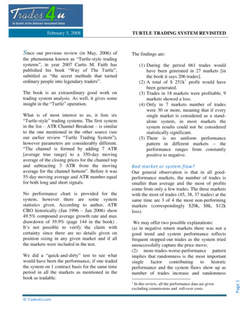
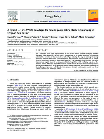
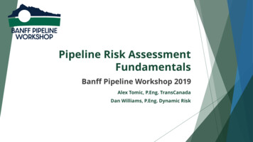
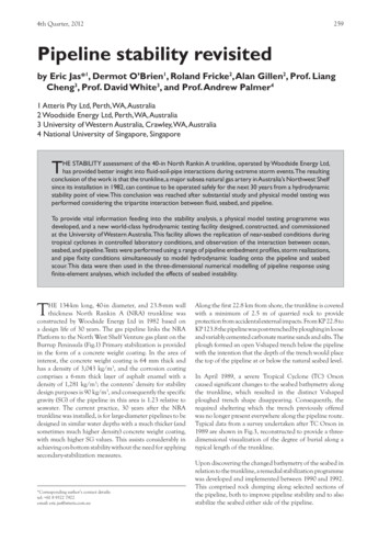
4th Quarter, 2012259Pipeline stability revisitedby Eric Jas*1, Dermot O’Brien1, Roland Fricke2, Alan Gillen2, Prof. LiangCheng3, Prof. David White3, and Prof. Andrew Palmer41 Atteris Pty Ltd, Perth, WA, Australia2 Woodside Energy Ltd, Perth, WA, Australia3 University of Western Australia, Crawley, WA, Australia4 National University of Singapore, SingaporeTHE STABILITY assessment of the 40-in North Rankin A trunkline, operated by Woodside Energy Ltd,has provided better insight into fluid-soil-pipe interactions during extreme storm events.The resultingconclusion of the work is that the trunkline, a major subsea natural gas artery in Australia’s Northwest Shelfsince its installation in 1982, can continue to be operated safely for the next 30 years from a hydrodynamicstability point of view. This conclusion was reached after substantial study and physical model testing wasperformed considering the tripartite interaction between fluid, seabed, and pipeline.To provide vital information feeding into the stability analysis, a physical model testing programme wasdeveloped, and a new world-class hydrodynamic testing facility designed, constructed, and commissionedat the University of Western Australia. This facility allows the replication of near-seabed conditions duringtropical cyclones in controlled laboratory conditions, and observation of the interaction between ocean,seabed, and pipeline.Tests were performed using a range of pipeline embedment profiles, storm realizations,and pipe fixity conditions simultaneously to model hydrodynamic loading onto the pipeline and seabedscour. This data were then used in the three-dimensional numerical modelling of pipeline response usingfinite-element analyses, which included the effects of seabed instability.THE 134-km long, 40-in diameter, and 23.8-mm wallthickness North Rankin A (NRA) trunkline wasconstructed by Woodside Energy Ltd in 1982 based ona design life of 30 years. The gas pipeline links the NRAPlatform to the North West Shelf Venture gas plant on theBurrup Peninsula (Fig.1) Primary stabilization is providedin the form of a concrete weight coating. In the area ofinterest, the concrete weight coating is 64 mm thick andhas a density of 3,043 kg/m3, and the corrosion coatingcomprises a 6-mm thick layer of asphalt enamel with adensity of 1,281 kg/m3; the contents’ density for stabilitydesign purposes is 90 kg/m3, and consequently the specificgravity (SG) of the pipeline in this area is 1.23 relative toseawater. The current practice, 30 years after the NRAtrunkline was installed, is for large-diameter pipelines to bedesigned in similar water depths with a much thicker (andsometimes much higher density) concrete weight coating,with much higher SG values. This assists considerably inachieving on-bottom stability without the need for applyingsecondary-stabilization measures.*Corresponding author’s contact details:tel: 61 8 9322 7922email: eric.jas@atteris.com.auAlong the first 22.8 km from shore, the trunkline is coveredwith a minimum of 2.5 m of quarried rock to provideprotection from accidental external impacts. From KP 22.8 toKP 123.8 the pipeline was post-trenched by ploughing in looseand variably cemented carbonate marine sands and silts. Theplough formed an open V-shaped trench below the pipelinewith the intention that the depth of the trench would placethe top of the pipeline at or below the natural seabed level.In April 1989, a severe Tropical Cyclone (TC) Orsoncaused significant changes to the seabed bathymetry alongthe trunkline, which resulted in the distinct V-shapedploughed trench shape disappearing. Consequently, therequired sheltering which the trench previously offeredwas no longer present everywhere along the pipeline route.Typical data from a survey undertaken after TC Orson in1989 are shown in Fig.3, reconstructed to provide a threedimensional visualization of the degree of burial along atypical length of the trunkline.Upon discovering the changed bathymetry of the seabed inrelation to the trunkline, a remedial stabilization programmewas developed and implemented between 1990 and 1992.This comprised rock dumping along selected sections ofthe pipeline, both to improve pipeline stability and to alsostabilize the seabed either side of the pipeline.
260The Journal of Pipeline EngineeringFig.1.The NRA trunkline.The desire to extend the lifespan of the trunkline beyond2012 triggered the need to undertake a rigorous engineeringassessment of this asset. It included a study of thehydrodynamic stability of the system for the next 30 years.A screening process indicated that the critical areathat needed thorough review was the section along theContinental Shelf, between the 26 m and 73 m water depthcontours, or between KP 22.8 and KP 116. The two adjacentpipeline sections were either stabilized by quarry rock (theshore approach) or stable under the pipeline’s own weight(the platform approach).The challenges faced by the pipeline engineers who carriedout the assessment were the following: The trunkline comprises sections with highly variablelevels of embedment in sediments, ranging between0% (of pipeline diameter) to 100% or more. Along many of these areas, the level of embedmenteither side of the trunkline is not the same; in someareas there is as much as 100% embedment on oneside with little to no embedment on the other side. At the commencement of the assessment there wasinsufficient clarity as to the degree of instability ofthe seabed in the immediate vicinity of the trunkline. The SG of the trunkline (1.23 in seawater) alongthe area of interest is relatively low. A review of existing 3D pipeline-stability softwarepackages indicated that they would be inadequateto undertake the assessment accurately in the givenseabed conditions, unless considerable modificationswere made to the software to account for the effects ofseabed instability onto the pipeline-response model. The Northwest Shelf of Western Australia comprisescarbonate soils, and international pipeline codes andrecommended practices are written on the basis ofany seabed sand being siliceous.In summary, the assessment required an unconventionalmethodology in view of the nature of the sediments, thepotential effects of seabed instability, and the pipelineembedment levels, which are not compatible with theexisting codes and recommended practices.At the time when the assessment commenced (2006) theonly available and reliable recommended practice was DNVRP E305 [1], which: does not provide guidance on pipe-seabed interactionforces for pipelines on carbonate soils; does not allow for the effect of pipeline embedmenton soil resistance and hydrodynamic loading; and does not consider the effects of seabed instabilitywithin the response of the pipeline during stormloading.The successor to DNV RP E305, published in 2007, isDNV RP F109 [2]. This updated code does allow forsome effects of pipeline embedment; however it does notconsider asymmetrical embedment levels, and also doesnot provide quantitative guidance for carbonate soils. Bothrecommended practices focus on pipeline on-bottom stabilitywith relatively low embedment levels, and are not suitedto the assessment of highly embedded pipeline sections.In addition, none of the existing codes and recommendedpractices considers the effects of the changes in seabedbathymetry and characteristics during a storm event –i.e. when subjected to the wave- and current-inducedhydrodynamic loads – on pipeline stability. Such changes caninclude sediment scour and deposition, excess pore pressurebuild-up and dissipation and, sometimes, liquefaction.The pipeline engineers who undertook the assessmentconsidered these effects of great importance. It has beenmentioned before that the seabed, if it comprises a fine- ormedium-sized uncemented material, will lose strength andbecome mobile during the ramp-up period of a storm, longbefore the pipeline becomes unstable [3], depending onthe SG of the pipeline. Whilst the recommended practicesand guidelines do not incorporate these effects within theirmethodologies, many pipelines that are in operation have atrack record of losing contact with the seabed over sometimes
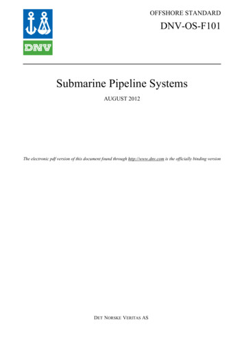
4th Quarter, 2012261Fig.2.Typical as-built post-lay ploughed trench profile.Project ExecutionPlanStep 1Input Data GatheringStep 2Seabed StabilityStep 32D Pipeline On-BottomStabilityStep 4Rock Berm StabilityAssessmentStep 52D Physical ModelFig.3.Various levels of pipeline embedment post-TropicalCyclone Orson.significant lengths in areas of loose sediments through theforming of scour holes. The forming of scour holes alonga pipeline can sometimes be so extensive that the pipeline,depending on its SG, experiences self-burial over time.MethodologyAs a consequence of the limitations in the design codes andrecommended practices, an unconventional methodologywas developed for this case (Fig.4). The aim of the stabilityassessment was to develop an understanding of the processescontributing to the stability (or instability) of the trunklineand to assess whether satisfactory evidence can be gatheredto demonstrate that the risk of future trunkline instabilityis sufficiently low.The following main steps were identified when developingthe methodology of the stability assessment of the NRAtrunkline.Overview of the assessmentInput data gatheringThe NRA trunkline had previously been the subject ofmuch study, in particular in relation to its hydrodynamicstability. A significant amount of data had been collectedStep 63D Stability AssessmentTrunklineStable?Step 7Remedial StabilisationDesignStep 8Redefine TrunklineStability CriteriaClose-Out ReportFig. 4.The assessment process.over more than two decades, including survey data fromannual and post-tropical cyclone inspections. Also, paststudies which had assessed the potential of the seabedsediments along the pipeline route to liquefy and/or scourwere studied. Mechanical design properties of the trunklinewere also collated to create an overall picture of the assetand its environment.Table 1 presents the metocean data applicable to the sectionof the pipeline route between KP 52 and KP 63. The seabedalong this section of the pipeline route comprises a 1 - 2m thick layer of fine- to medium-carbonate sand overlyinga calcareous rock pavement. The sand has a D50 of 150 200 microns.
262The Journal of Pipeline EngineeringDescriptionSymbolValueSignificant wave heightHs12.94 mPeak periodTp14.76 sWater depthd55.8 mSignificant wave-induced current(perpendicular to pipeline)Us1.62 m/sSteady-state current (perpendicular to pipeline)VR0.52 m/sMaximum wave-induced current(perpendicular to pipeline)Umax2.46 m/sTable 1. NRA trunkline 100-year RP design metocean data (from KP 52 to KP 63).Seabed stability assessmentThe pipeline engineers who undertook the assessmentrecognized that the overall stability of the pipeline dependson the tripartite interaction between the hydrodynamicloads induced by tropical cyclones, the seabed – comprisingpredominantly calcareous sediments – and the trunkline.Consequently, an in-depth study of these processeswas undertaken.As a starting point, the interaction between the hydrodynamicloads and the seabed was assessed. Specialists were engagedto undertake seabed liquefaction and scour analyses.The seabed liquefaction analysis performed for this project,which used the methodology described by Bonjean et al.[4] concluded that, although the large hydrostatic pressurefluctuations caused by tropical-cyclone-induced waves do nothave the capacity to induce free-field seabed liquefaction,it is likely that loose and fine sediments deposited withinthe open trench would have liquefied during a significantstorm event (such as TC Orson in 1989). This would havecaused lift of the pipeline by several tens of centimetres. Theend result, after a significant storm, created a picture whichwas perceived at the time by many as a general lowering ofthe seabed (due to regional scour), while in reality it couldwell have been the pipeline which had risen.This trench backfill material liquefaction theory is consideredto be the most likely explanation for the observed changein the burial of the NRA trunkline. It casts doubt onto thevalidity of the broadly accepted regional-scour theory, or atleast the depth extent of such seabed erosion and its effecton submarine structures such as pipelines in this region.The seabed-liquefaction assessment also concluded thatwhere soils are classified as sand, excess pore pressure buildup around the pipeline during an extreme load conditionis expected to be small (5 - 10%), which is not expected toimpact pipeline stability. However, where soils are classifiedas silty sand, excess pore pressure build-up around thepipeline can be much higher under extreme load conditions(60 - 70%) which may be expected to cause localized partialflotation of the pipeline.Excess pore pressure build-up will result in soil softening andreduced soil passive resistance, and could result in partialpipeline flotation where significant excess pore pressuresare generated. However, it is difficult to precisely correlatea decrease in lateral soil resistance to a value of excess porepressure. Although excess pore pressures generated in theregion where the pipeline stability has been analysed in detailare not expected to have a significant effect, sensitivity loadcases have been performed in the 3D FEA analysis usingreduced soil passive-resistance values to assess the potentialeffects of excess pore pressure build-up on pipeline stability.A regional (free-field) scour analysis was also performed.Two independent methods were used: the first used theSoulsby method [5] to determine the volume of sedimentsuspended in the water column, while the second assessedthe possibility of sheet flow, using the Flores and Sleathmethod [6] to estimate the regional (free-field) scour depth.The regional scour analysis indicated that over the long term,the regional scour depth is like
The successor to DNV RP E305, published in 2007, is DNV RP F109 [2]. This updated code does allow for some effects of pipeline embedment; however it does not consider asymmetrical embedment levels, and also does not provide quantitative guidance for carbonate soils. Both recommended practices focus on pipeline on-bottom stability with relatively low embedment levels, and are not suited to the .