Transcription
Lesson 1Introduction to Mastercam V9Introduction To Mastercam V9Lesson 1 is developed to get you the user, familiar with the Mastercam software. Youwill be introduced to the screen layout as well as the tools and menus. This lesson hastools, menus and a quick key list that will be a valuable resource throughout the entirebook.There are a few short tutorials that take you through the steps required to create lines,circles and rectangles. These short tutorials show you how to create basic geometry butalso demonstrate how to get a round in the Mastercam environment.The next section shows you where and how to make some basic customizations to theMastercam layout, such as background color, grid size etc.The last section is a short summarization of the entire lesson. This lesson also has theLesson 1 Review section which consists of twenty review questions. If a hands-onreview is what you’re best at there are five practice exercises in the Lesson 1 Exercisessection.Lesson 1 ObjectivesThe objective of this lesson is to introduce you the user to Mastercam V9. When you are donewith this lesson you should have an understanding of the following:a.) How to start Mastercam V9 and know what some of the start options are.b.) Mastercam V9 screen layout.c.) Mastercam V9 tool options.d.) Mastercam V9 quick key options.e.) How to start and save a Mastercam V9 design file.f.) How to create a basic 2D geometry.g.) How make basic modifications to the Mastercam properties.
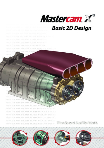
1-2Introduction To Mastercam V9The purpose of this Lesson is to give you the user the knowledge (tools) to get around inthe Mastercam V9 and the tools to create simple geometry. This information is a vitalfoundation for the following lessons to build upon.Starting Mastercam V9It is assumed that you have some computer experience in basic windows operations. Ifthis is not the case consult your Microsoft Windows handbook and/or Help file. You canaccess the windows help menu under Start (lower left corner of your computer screen)then select Help.After the computer has been started and the boot up is completed look on theWindows Desktop for a Mill 9 shortcut. Reference the shortcut icon to theright. If a shortcut is not available complete the following steps to startMastercam (reference Figure 1.1):1.) From the Windows desktop select Start from the lower left of your computerscreen.2.) Select All Programs. All Programs displays all the software programs loadedand available on your computer. Scan through the list until you locate theMastercam 9 option.Figure 1.1
Screen Layout & Tools1-33.) Select Mastercam 9 from the programs list. This will bring up a list ofMastercam options. The Design 9 option will allow you to create geometry only.The Mill 9 option will allow you to create geometry and create tool paths. Tosimplify the step select the Mill 9 option.4.) Depending on your Mastercam license and setup, you will be prompted to acceptthe license agreement prior to being allowed to enter Mastercam V9. Accept thelicense agreement to enter Mastercam V9 program.You know that you are in Mastercam program when your screen looks similar to the oneshown in Figure 1.2. At this point you can open an existing file or start a new one. Thefollowing section familiarizes you with the Mastercam screen layout and tools.
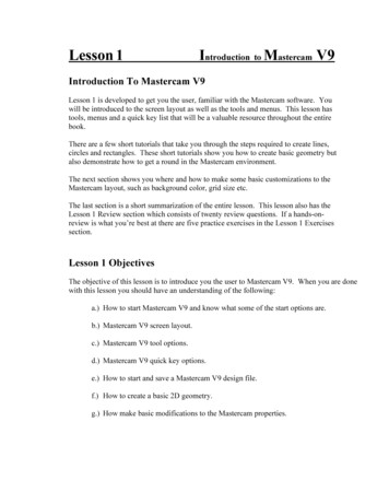
1-4Introduction To Mastercam V9Mastercam V9 Standard Menus And ToolsThe following standard screen layout shows you where different tools and tool bars arelocated. The numbers coordinate with the following pages where the tool label is bolded.The tool label is followed by a brief explanation and in some cases, steps on how to useand/or access the tool.Figure 1.2123456789101112131415The following list of menus is not meant to be a comprehensive definition of every toolon the standard Mastercam V9 screen. The purpose is to provide a quick reference andan introduction with a brief explanation. If more detailed information is needed and/orrequired, refer to the Mastercam V9 Help menu and/or Internet homepage.
Screen Layout & Tools1-5Menu 1The Mastercam Program IdentifierThis part of the screen is used to identify the particularMastercam program that is loaded and the program version. The options are Mill, Latheand Design.Menu 2Toolbar MenuThis horizontal bar of tool icons stretches across the entire upper portion of the screen.The icons represent tools that can be accessed in the design and mill operations. Most ofthe tools can also be selected from the Main Menu area as well. The following gives abrief description on each tool. Alt B hides/shows the toolbar. Some tools bring upwindows, some menus and others are just toggle tools.ToolBarToolNamePreviousPageNext PageHelpFileAnalyzeScreenZoomScreenUTool DefinitionThis tool allows you to scroll back through the Toolbar menu.There are too many tools to be displayed all at the same timethus the need for the scroll tools.This tool allows you to scroll forward through the Toolbar. Itscrolls opposite direction of the previous tool.This tool brings up the Mastercam V9 Help window. This is avery helpful tool, use it! Alt H is the Help quick key.This tool can also be selected from the Main Menu. Selecteither the tool icon or from the Main Menu and the MenuHeading changes to the active tool. Reference Menu 3. If youselect the tool icon reference the Main Menu (Menu 4) todisplay the additional options under File.This tool allows you to analyze the design and or mill geometrycreated on the work area of the screen. Notice that the Analyzeoption is also listed on the Main Menu. When either the icon orMain Menu options is selected the additional options aredisplayed.The user is prompted to select a rectangular window to zoom inon.This tool automatically unzooms (zooms out).
1-6Introduction To Mastercam V9UnzoomUnzoom by0.8Screen FitScreenRepaintGview DynamicGview IsometricZooms out from the displayed image in increments of 0.2.This tool automatically fits the displayed image to the graphicscreen area.Refreshes the screen, gets rid of remnant geometry.This tool allows the user to rotate the geometry in all threedimensions.This tool allows the user to view the created geometry from anIsometric View point.This tool allows the user to view the created geometry from aGview -TopTop View point.This tool allows the user to view the created geometry from aGview Front View point.FrontThis tool allows the user to view the created geometry from aGview Side View point.SideThe construction plane is the active plane that the geometry isCplaine created on. This tool makes the top plane the active constructionTopplane.This tool makes the front plane the active construction planeCplane FrontThis tool makes the side plane the active construction plane.Cplaine SideThis tool makes it possible to create geometry in 3D. Theprevious three tools restricted geometry creation to 2D. ThisCplane-3Dmeans you must define geometry in terms of 3D, such as a pointrequires an X, Y and Z value.This tool allows the user to delete selected orsScreenClearColorsThis tool allows you to undo the last deletion.This tool brings up the Change Color menu. The tool allows theuser to change the color of selected geometry.This tool makes all geometry the same color and/or group.This tool allows you to undo the last operation as long as you arein the same menu the operation was executed in.Screen Surf This tool allows you to apply the shading to surfaces.DispShadingThis tool brings up the Blank menu allowing you to blank selectScreengeometrical entities.BlankUndo
Screen Layout & faceCreateSolidCreateSolidsHistory1-7This tool list all the geometrical entities created. Theinformation is displayed in the Prompt Zone.This tool brings up the Create/Line menu.This tool brings up the Create/Arc menu.This tool brings up the Create/Fillet menuThis tool brings up the Create/Spline menu.This tool brings up the Create/Rectangle menu.This tool brings up the Create/Point menu.This tool brings up the Create/Surface menu.This tool brings up the Create/Solid menu.This tool brings up the Solids History. This tool allows you tosee the steps used to create the resultant solid.Menu 2Toolbar Menu ContinuedThis horizontal bar of icons is what will be displayed when you select the Next tool.Previous Page Use this button to scroll through the Toolbar.Next PageUse this button to scroll through the Toolbar.Modify-Trim1 EntityModify-Trim2 EntityModify-Trim3 EntityModify-TrimDivideModifyExtendThis tool brings up the Modify/Trim/1 Entity function in thePrompt Zone.This tool brings up the Modify/Trim/2 Entity function in thePrompt Zone.This tool brings up the Modify/Trim/3 Entity function in thePrompt Zone.This tool brings up the Modify/Trim/Divide function in thePrompt Zone.This tool brings up the Modify/Extend menu. Also notice theinformation displayed in the Prompt Zone.
1-8Introduction To Mastercam V9Modify-Break This tool brings up the Modify/Break menu.This tool brings up the Modify/Normal menu. This tool dealsspecifically with surfaces.This tool brings up the Modify/Mirror menu. This tool is ashortcut for the Xform option found in the Main Menu.This tool brings up the Modify/Rotate menu. This tool is aXform-Rotateshortcut for the Xform option found in the Main Menu.This tool brings up the Xform/Scale menu. This tool is aXform-Scale shortcut for the Xform option found in the Main Menu.This tool brings up the Xform-Translate menu. This tool is aXformshortcut for the Xform option found in the Main Menu.TranslateThis tool brings up the Offset window. This allows you toXform-Offsetcreate duplicate entities a specified distance apart.This tool is a toggle tool from the following information: Thequick key is F9.Screen- Current axis system.Display Info- Current geometry file information.- Current Toolpath file information.This tool tracks the location of the cursor, it is a toggle tool.CursorTracking(Toggle)This tool brings up the Create/Drafting/Dimension menu.CreateDraftingDimensionThis tool brings up the Drafting Global window. ThisDraft Globalwindow is where you set the drafting parameters.This tool brings up the System Configuration window. ThisScreenwindow is where you can set Mastercam default and systemsConfigurationdefaults.This tool brings up the Tooplpaths/Contour menu. The toolToolpathsis used to create a Contour Toolpath.ContourThis tool brings up the Tooplpaths/Drill menu. The tool isToolpathsused to create a Drill Toolpath.DrillThis tool brings up the Tooplpaths/Pocket menu. The tool isToolpathsused to create a Pocket Toolpath.PocketThis tool brings up the Tooplaths/Flowline menu.TooplpathsFlowlineThis tool brings up the Toolpaths/Surface menu.ToolpathsSurfaceThis tool brings up the NC Utils/Backplot menu.NC UtilsBackplotThis tool brings up the Mastercam Rebuilds Display ListScreenwindow. This tool is used to optimize Mastercam.RegenerateThis tool brings up the NC Utils/Filter menu.NC UtilsFilterModifyNormalXformMirror
Screen Layout & ToolsNC Utils-PostProcFile-dos ShellFileCommunicScreenViewportFile New1-9This tool brings up the NC Utils/Post Proc menu.This tool brings up a DOS window and Dos prompt.This tool brings up a Communications window.This tool brings up the Viewport window. The tool allowsyou to define multiple screen configurations.This tool allows you to start a new Mastercam session.Create Ellipse This tool brings up the Create Ellipse window.Create his brings up the Create/Line/Multi menu. This tool is aquick way to creating a line using a specific method.This brings up the Create/Line/Horizontal menu. This tool isa quick way to creating a line using a specific method.This brings up the Create/Line/Vertical menu. This tool is aquick way to creating a line using a specific method.Menu 2Toolbar Menu Continued, AgainThis horizontal bar of icons is what will be displayed; select the Next tool for the secondtime.PreviousPageNext tsUse this button to scroll through the Toolbar.Use this button to scroll through the Toolbar.This brings up the Create/Line/Endpoints menu. This tool is aquick way to creating a line using a specific method.This tool brings up the Create/Line/Polar menu. This tool is aquick way to creating a line using a specific method.This tool brings up the Create/Line/Parallel menu. This tool isa quick way to creating a line using a specific method.This tool brings up the Create/Arc/Polar/Centerpoint menu.This tool is a quick way to creating a circle/arc using a specificmethod.This tool brings up the Create/Arc/Endpoint menu. This tool isa quick way to creating a circle/arc using a specific method.
1-10Introduction To Mastercam V9FileRamsaverScreenChangeAttributesToolpathsJob SetupToolpathOparationsManagerWCS ViewManagerDelete eDimensionOrdinateCreateDimensionPointThis tool allows you to automatically delete duplicate geometry.This tool brings up the Screen Change Attributes window. Thiswindow allows you to specify the attributes of geometricalentities.This tool brings up the Toolpaths Job Setup window. Thiswindow is where you can define the parameters of a toolpathsuch as raw stock, toolpath configuration and material.This tool brings up the Toolpath Operations Manager window.This tool brings up the WCS View Manager window.This tool allows you to delete the last toolpath operation.This tool brings up the Create Drafting menu.This tool brings up the Create/Drafting/Dimension/Horizontalmenu.This tool brings up the Create/Drafting/Dimension/Verticalmenu.This tool brings up the Create/Drafting/Dimension/Parallelmenu.This tool brings up the Create/Drafting/Dimension/Angularmenu.This tool brings up the Create/Drafting/Dimension/Circularmenu.This tool brings up the Create/Drafting/Dimension/Circularmenu.This tool brings up the Create/Drafting/Dimension/Baselinemenu.This tool brings up the Create/Drafting/Dimension/Chainedmenu.This tool brings up the Create/Drafting/Dimension/Ordinatemenu.This tool brings up the Create/Drafting/Dimension/Pointmenu.
Screen Layout & )1-11This tool brings up the Note Dialog window. The Note Dialogwindow allows you to create text notes.This tool brings up the Hatch window. This window allows youto select the type of hatch you want to apply to the geometry.This tool allows you to Create and save a Macro.This tool allows you to load and Play a Macro.This tool allows you to Pause the current Macro.Menu 3The Main Menu IdentifierThis area of the window identifies the active menu option. The options can be selectedfrom the Main Menu selection or from the Toolbar option.
1-12Introduction To Mastercam V9Menu 4The Main MenuThe options shown in this menu are Mastercam V9’s main tools. Notice that most of theoptions also are the first few tools represented in the Toolbar (Menu 2). Once the mainoption is selected the next level of options are displayed. Menu 3 helps you keep track ofwhere in the menu option you are by labeling the menu option. Notice that the eachoptions has one letter underlined. The under lined letter is a Quick Key to activating theparticular tool.Tool BarTool NameTool DefinitionAnalyzeThis option allows you to analyze the design and or millgeometry in the work area of the screen.CreateThis option allows you to create geometrical and draftingentities, such as lines and dimensions.FileThis option allows you to save, get, import and/or exportMastercam files.ModifyThis option gives you access to all the tools used tomodify existing geometry such as trim and extend.XfromDeleteScreenSolidsToolpathsNC UtilsThis option gives you access to all the tools that allowyou to transform existing geometry such as mirror androtate.This option allows you several different methods ofselecting the entities you want to delete.This option gives you access tools that allow you tomodify and or define all parameters related to theMastercam screen and layout defaults.This option gives you access to the Solids tools.This option is where you go to create the toolpaths suchas contour, drill and pocket.This option is where you have access to the toolpathdefaults, setup and verification tools.
Screen Layout & Tools1-13Menu 5The Backup Menu ToolThis tool is a handy tool, it allows you to backup one menu level at a time.Menu 6The Main Menu ToolThis tool allows you to jump directly back to the main menu no matter where or whatlevel of a particular menu you are at.Menu 7The Secondary Menu ToolsThis Toolbar controls the graphical aspect of the entities in the work area.Tool BarTool NameTool DefinitionZ: HeightThis status bar indicates the current Z value.This status bar indicates the current color and itsassigned number.This status bar indicates the current (active) Level.Selecting this tool brings up the Level Managerwindow. From this window you can create and changethe current level.This tool brings up the Attributes window. In theAttributes window you can change the color, type andthickness of the geometrical entities.This tool brings up the Groups window. In thiswindow you can create new and modify existinggroups.Selecting this tool will bring up the Level Managerwindow where you can turn the levels Off or On(mask). This tool also gives the current status of theMask.Color:Level:AttributesGroupsMask:
1-14Introduction To Mastercam V9WCS:Tplane:Cplane:Gview:This tool brings up the View Manager window.This tool brings up the Tool Plane menu, where youcan specify what tool plane you require (Front, Top,Side ). Notice it also shows the status (activeTPlane).This tool brings up the Construction Plane menu,where you can specify what tool plane you require(Front, Top, Side ). Notice it also shows the status(active CPlane).This tool brings up the Gview menu, where you canspecify what specific view you want your geometry toshown in. Notice it also shows the status (activeGview).Menu 8The Prompt ZoneThis area of the screen is reserved for prompting the user for specific input. The promptmessage will depend on what tools has been selected. The example shown is the promptmessage after selecting Create from the Main Menu and Line in the second level menu.Menu 9The Units DisplayThis area of the screen is dedicated to identifying the units the file is being created, editedand saved in.
Screen Layout & Tools1-15Menu 10The Axis OrientationThis tool shows the orientation and/or working plane. By default you will be working inthe X, Y plane as shown. If you rotate to a new work plane the Axis will show you thecurrent orientation three dimensionally as shown below the two dimensional axis.Menu 11The Zoom Screen ScaleThis information displays the zoom screen value. This display can be turned off selectingthe F9 key. If you select the Alt F2 you can verify the zoom value to change inincrements of .2.Menu 12The Axis IdentifierThe first axis is two dimensional with the x, y plane active. The second axis is rotated toan isometric view. This tool helps identify the orientation of the work space as well asthe 0,0,0 point. This tool is a toggle tool, F9 turns the axis display on and off.
1-16Introduction To Mastercam V9Menu 13The Cursor Location DisplayThis area is dedicated to displaying the location of the cursor in the work area. You canmove the cursor around in the work space. Notice the values update to the new locationof the in reference to 0,0,0. Alt F3 toggles this display On and Off.Menu 14The Standard Window ToolsThese tools are the standard
Introduction To Mastercam V9 Lesson 1 is developed to get you the user, familiar with the Mastercam software. You will be introduced to the screen layout as well as the tools and menus. This lesson has tools, menus and a quick key li