Transcription
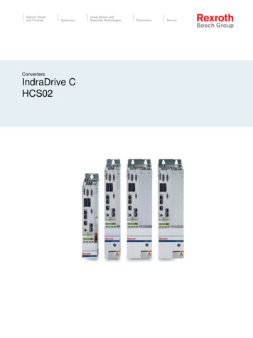
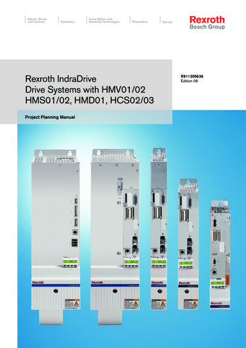
Electric Drivesand ControlsHydraulicsLinear Motion andAssembly TechnologiesPneumaticsRexroth IndraDriveDrive Systems with HMV01/02HMS01/02, HMD01, HCS02/03Project Planning ManualServiceR911309636Edition 06
Bosch Rexroth AGTitleDOK-INDRV*-SYSTEM*****-PR06-EN-PRexroth IndraDrive Drive Systems with HMV01/02 HMS01/02, HMD01, HCS02/03Rexroth IndraDriveDrive Systems with HMV01/02HMS01/02, HMD01, HCS02/03Type of DocumentationDocument TypecodeInternal File ReferenceRecord of RevisionCopyrightProject Planning a6846ac00a015a26f840210-5-en-US-3EditionRelease DateNotes0408/2007-0509/2009-0608/2013Changes: See index en‐try "Changes" Bosch Rexroth AG 2013This document, as well as the data, specifications and other information setforth in it, are the exclusive property of Bosch Rexroth AG. It may not be re‐produced or given to third parties without its consent.LiabilityPublished byThe specified data is intended for product description purposes only and shallnot be deemed to be a guaranteed characteristic unless expressly stipulatedin the contract. All rights are reserved with respect to the content of this docu‐mentation and the availability of the product.Bosch Rexroth AGBgm.-Dr.-Nebel-Str. 2 97816 Lohr a. Main, GermanyPhone 49 9352 18 0 Fax 49 9352 18 8400http://www.boschrexroth.com/DC-IA/EDH1 (DH); DC-IA/EDY1 (RB/US/BB)
DOK-INDRV*-SYSTEM*****-PR06-EN-PRexroth IndraDrive Drive Systems with HMV01/02 HMS01/02, HMD01, HCS02/03Bosch Rexroth AGI/309Table of ContentsTable of .13.3.2System Presentation. 11System Platform. 11Drive System Rexroth IndraDrive C - Compact Converters. 12Drive System Rexroth IndraDrive M - Modular System. 14Drive System Rexroth IndraDrive Mi. 17Drive Systems with KCU01. 17Drive Systems with KCU02. 20Combinations of Rexroth IndraDrive C with Rexroth IndraDrive M and Rexroth IndraDrive Mi. 24Basic Design of the Devices. 24General Information. 24Power Section. 24Control Section. 25Overview of Type Currents and Type Performances. 26General Information. 26Drive Controllers. 26Supply Units and Converters. 27Overview of Functions. 28Supply Units and Power Sections. 28Control Sections. 28Documentations. 28About This Documentation. 28Overview of Documentations. 29Drive Systems, System Components. 29Motors. 30Cables. 31Firmware. 31Your Feedback. 34Important Directions for Use . 35Appropriate Use . 35Introduction. 35Areas of Use and Application. 35Inappropriate Use. 36Safety Instructions for Electric Drives and Controls. 37Definitions of Terms. 37General Information. 38Using the Safety Instructions and Passing Them on to Others. 38Requirements for Safe Use. 38Hazards by Improper Use. 39Instructions with Regard to Specific Dangers. 40Protection Against Contact with Electrical Parts and Housings. 40Protective Extra-Low Voltage as Protection Against Electric Shock . 41
II/309Bosch Rexroth AGDOK-INDRV*-SYSTEM*****-PR06-EN-PRexroth IndraDrive Drive Systems with HMV01/02 HMS01/02, HMD01, HCS02/03Table of 3.45.45.5Protection Against Dangerous Movements. 42Protection Against Magnetic and Electromagnetic Fields During Operation and Mounting. 43Protection Against Contact with Hot Parts. 44Protection During Handling and Mounting. 44Battery Safety. 44Protection Against Pressurized Systems. 45Explanation of Signal Words and the Safety Alert Symbol. 45Brief Description, Usage. 47General Information. 47Applications of the Drive System Rexroth IndraDrive. 47Mains Transformers DST and DLT. 47Mains Filters HNF, HNK, NFE, HNS02 and NFD. 47Mains Chokes HNL01 and HNL02. 48Supply Units HMV01 / HMV02. 49Drive Controllers HMS01, HMS02 and HMD01. 49Control Sections CSB, CSE, CSH, CDB. 49Drive Controllers HCS02. 50Drive Controllers HCS03. 50Components KCU, KSM, KMS. 50DC Bus Resistor Unit HLB01. 51Braking Resistor HLR01. 51DC Bus Capacitor Unit HLC01. 52Fan Unit HAB01. 52Motor Filters HMF01. 52Accessories HAS. 52Housing for Control Sections HAC01. 52Hall Sensor Box SHL. 52General Data and Specifications. 55Acceptance Tests and Approvals. 55Transport and Storage. 57Transport of the Components. 57Storage of the Components. 58Installation Conditions. 58Ambient and Operating Conditions. 58Mounting Position. 62Mounting Positions of Components. 62Mounting Positions of Motor-Integrated Servo Drives. 63Compatibility With Foreign Matters. 63Motor Paint Coat. 64Voltage Test and Insulation Resistance Test. 64Control Voltage (24V Supply) . 65
DOK-INDRV*-SYSTEM*****-PR06-EN-PRexroth IndraDrive Drive Systems with HMV01/02 HMS01/02, HMD01, HCS02/03Bosch Rexroth AGIII/309Table of 27.5.37.5.47.5.588.18.28.2.18.2.2Project Planning of Control Voltage (24V Supply). 67General Information. 67Selecting the 24V Supply. 67General Information. 67Electrical Requirements. 68Installing the 24V Supply. 70Looping Through the Control Voltage Supply. 71Project Planning of Mains Connection . 73General Information. 73Mains Voltage Supply . 73Mains Types. 76TN-S Mains Type. 76TN-C Mains Type. 76IT Mains Type. 77TT System. 78Mains Grounded via Outer Conductor (Corner-Grounded Delta Mains). 79Mains Short-Circuit Power and Mains Connected Load . 79General Information. 79Mains Short-Circuit Power. 80Mains Connected Load. 81Protection Systems at the Mains Connection. 84General Information. 84Protective Grounding. 85General Information. 85Fusing by Protective Grounding in TN-S Mains. 86Fusing by Protective Grounding in TN-C Mains. 87Fusing by Protective Grounding in IT Mains (Ungrounded Mains). 88Connection for the Equipment Grounding Conductor. 89General Information. 89Equipment Grounding Connection Between the Components. 89Connecting Equipment Grounding Conductor to Mains. 89Residual-Current-Operated Circuit Breakers (RCD, RCCB) as Additional Fusing. 89General Information. 89Cause of Leakage Currents. 90Possibilities of Use. 90Using Residual-Current-Operated Circuit Breakers at HCS Drive Controllers. 91Using Residual-Current-Operated Circuit Breakers at HMV Supply Units. 92Insulation Monitoring Devices. 92Configuring the Drive System. 93General Information. 93Type of Supply for Power Sections. 93General Information. 93HMV Supply Units for HMS/HMD Power Sections. 96
IV/309Bosch Rexroth AGDOK-INDRV*-SYSTEM*****-PR06-EN-PRexroth IndraDrive Drive Systems with HMV01/02 HMS01/02, HMD01, HCS02/03Table of .78.7.18.7.2Central Supply HMV. 96Parallel Operation HMV - Group Supply with DC Bus Connection HMV01, HMV02. 98Converter HCS as Supply Unit. 99General Information. 99Central Supply - HCS Supply HCS or HMS/HMD Drive Controllers. 99Parallel Operation HCS - Group Supply with DC Bus Connection of the Groups. 102Third-Party Supply Units. 105General Information. 105Mains Connection Supply Units and Converters. 106General Information. 106Mains Connection of HMV Supply Units. 109Mains Connection of HMV Supply Units - Additional Components. 109Mains Connection of HMV01.1E Supply Units. 110Mains Connection of HMV01.1R Supply Units. 111Mains Connection of HMV02.1R Supply Units. 112Mains Connection for HCS Converters. 113Mains Connection for HCS Converters - Additional Components. 113Mains Connection for HCS02 Converters. 114Mains Connection for HCS03 Converters. 116Additional Components. 120Additional Components at the DC Bus. 120General Information. 120HLR Braking Resistors and DC Bus Resistor Units HLB. 122Additional Components at the Motor Output. 125General Information. 125HMF01 Motor Filters. 126Power Section, Control Section, Firmware . 126General Information. 126Power Section - Control Section. 127Control Section - Firmware . 127Power Section - Firmware. 128Motor - Firmware . 133Encoder System - Encoder Evaluation. 133Combination With Other Rexroth Components. 136Combination With Components of the Control Range Rexroth IndraControl V. 136Operator Terminals VCP. 136sercos Analog Converter. 136General Information. 136sercos Analog Converter. 136Connection Cables to Motor. 137General Information. 137Motor cable. 137General Information. 137Motor Cable Selection . 138Allowed Length of Motor Cable. 138Voltage Drop on Connection to Motor Holding Brake. 139
DOK-INDRV*-SYSTEM*****-PR06-EN-PRexroth IndraDrive Drive Systems with HMV01/02 HMS01/02, HMD01, HCS02/03Bosch Rexroth AGV/309Table of .310.210.310.3.110.3.210.3.3Mechanical Requirements. 139Third-Party Power Cables. 139Encoder Cables . 140Using Rexroth IndraDyn Motors. 140Rexroth IndraDyn H – Synchronous Kit Spindle Motors. 140Circuits for the Mains Connection. 141General Information. 141Mains Contactor, Bb Contact. 141Circuits for Mains Connection of Rexroth IndraDrive C Drive Controllers. 145General Information. 145Control of External Mains Contactor for HCS02 and HCS03. 145General Information. 145Standard Design for HCS02 and HCS03 Drive Controllers. 146Design for HCS02 and HCS03 Drive Controllers with Integrated 24V Control Voltage Supply. . . 147Circuits HCS02 and HCS03 with DC Bus Resistor Unit HLB01.1C or HLB01.1D. 148Circuits for Mains Connection of Rexroth IndraDrive M Supply Units. 154General Information. 154Parallel Operation HMV01. 155Deceleration in the Case of Disturbed Electronic System of Drive (DC Bus Short Circuit is Activated). 155General Information. 155Control Circuits With DC Bus Short Circuit (ZKS). 157Deceleration in the Case of Emergency Stop or Mains Failure. 166General Information. 166Control Circuit "Position-Controlled Deceleration by the Control Unit" without DC Bus Short Circuit(ZKS). 167Control Circuit Emergency Stop Relay without DC Bus Short Circuit (ZKS) . 169Signal Sequences When Switching HMV Supply Units ON and OFF. 177Switching On. 177Switching Off. 179Electromagnetic Compatibility (EMC). 181EMC Requirements. 181General Information.
Project Planning Manual Electric Drives and Controls Pneumatics Service Linear Motion and Hydraulics Assembly Technologies Rexroth IndraDrive Drive Systems with HMV01/02
