Transcription
The Drive & Control CompanyRexroth IndraDriveDrive ControllersPower Sections HMS01Instruction ManualEdition 07R911319996LSA Control S.L. www.lsa-control.com comercial@lsa-control.com ( 34) 960 62 43 01
Bosch Rexroth AGTitleDOK-INDRV*-HMS01*UL***-IB07-EN-PRexroth IndraDrive Drive Controllers Power Sections HMS01Rexroth IndraDriveDrive ControllersPower Sections HMS01Type of DocumentationDocument TypecodeInternal File ReferenceRecord of RevisionPurpose of DocumentationCopyrightInstruction 77f25760a6846a001b52ebf-9-en-US-2EditionRelease published ected ected ected ected ected ected editionThis documentation provides information on the installation and operation ofthe described products, by persons trained and qualified to work with electri‐cal installations. Bosch Rexroth AG 2014This document, as well as the data, specifications and other information setforth in it, are the exclusive property of Bosch Rexroth AG. It may not be re‐produced or given to third parties without its consent.LiabilityPublished byThe specified data is intended for product description purposes only and shallnot be deemed to be a guaranteed characteristic unless expressly stipulatedin the contract. All rights are reserved with respect to the content of this docu‐mentation and the availability of the product.Bosch Rexroth AGBgm.-Dr.-Nebel-Str. 2 97816 Lohr a. Main, GermanyPhone 49 9352 18 0 Fax 49 9352 18 8400http://www.boschrexroth.com/DC-IA/EDY4 (CR)LSA Control S.L. www.lsa-control.com comercial@lsa-control.com ( 34) 960 62 43 01
DOK-INDRV*-HMS01*UL***-IB07-EN-PRexroth IndraDrive Drive Controllers Power Sections HMS01Bosch Rexroth AGI/21Table of ContentsTable of ContentsPage11.11.1.11.1.21.1.31.2Important Notes. 3Safety Instructions.General Information.Protection against contact with electrical parts and housings.Battery safety.Appropriate Use.334562Ratings and dimensions. 73Overview of Documentations. 113.144.14.24.2.14.2.25Motors. 11Instructions for use. 13Power Supply and Input Voltage. 13Connection. 14Connection diagram. 14Connection points. 15Service and support. 17Index. 19LSA Control S.L. www.lsa-control.com comercial@lsa-control.com ( 34) 960 62 43 01
II/21Bosch Rexroth AGDOK-INDRV*-HMS01*UL***-IB07-EN-PRexroth IndraDrive Drive Controllers Power Sections HMS01LSA Control S.L. www.lsa-control.com comercial@lsa-control.com ( 34) 960 62 43 01
DOK-INDRV*-HMS01*UL***-IB07-EN-PRexroth IndraDrive Drive Controllers Power Sections HMS01Bosch Rexroth AG3/21Important Notes1Important Notes1.1Safety Instructions1.1.1General Information Do not attempt to install and operate the components of the electricdrive and control system without first reading all documentation providedwith the product. Read and understand these safety instructions and alluser documentation prior to working with these components. If you donot have the user documentation for the components, contact your re‐sponsible Rexroth sales partner. Ask for these documents to be sent im‐mediately to the person or persons responsible for the safe operation ofthe components. If the supplied documents contain some information you do not under‐stand, it is absolutely necessary that you ask Rexroth for explanationbefore you start working at or with the components. If the component is resold, rented and/or passed on to others in any oth‐er form, these safety instructions must be delivered with the componentin the official language of the user's country. Only qualified persons may work with components of the electric driveand control system or within its proximity.In terms of this Instruction Manual, qualified persons are those personswho are familiar with the installation, mounting, commissioning and op‐eration of the components of the electric drive and control system, aswell as with the hazards this implies, and who possess the qualificationstheir work requires. To comply with these qualifications, it is necessary,among other things,–to be trained, instructed or authorized to switch electric circuits andcomponents safely on and off, to ground them and to mark them,–to be trained or instructed to maintain and use adequate safetyequipment,–to attend a course of instruction in first aid. The technical data, connection and installation conditions of the compo‐nents are specified in the respective application documentations andmust be followed at all times. If the components take the form of hardware, then they must remain intheir original state, in other words, no structural changes are permitted.It is not permitted to decompile software components or alter source co‐des. Do not mount damaged or faulty components or use them in operation. Only use accessories and spare parts approved by Rexroth. Follow the safety regulations and requirements of the country in whichthe electric components of the electric drive and control system are op‐erated. Proper and correct transport, storage, mounting and installation, as wellas care in operation and maintenance, are prerequisites for optimal andsafe operation of the component.Improper use of these components, failure to follow the safety instructions inthis document or tampering with the product, including disabling of safety de‐vices, could result in property damage, injury, electric shock or even death.LSA Control S.L. www.lsa-control.com comercial@lsa-control.com ( 34) 960 62 43 01
4/21Bosch Rexroth AGDOK-INDRV*-HMS01*UL***-IB07-EN-PRexroth IndraDrive Drive Controllers Power Sections HMS01Important Notes1.1.2Protection against contact with electrical parts and housingsThis section concerns components of the electric drive and con‐trol system with voltages of more than 50 volts.Contact with parts conducting voltages above 50 volts can cause personaldanger and electric shock. When operating components of the electric driveand control system, it is unavoidable that some parts of these componentsconduct dangerous voltage.High electrical voltage! Danger to life, risk of injury by electric shock or seri‐ous injury! Only qualified persons are allowed to operate, maintain and/or repair thecomponents of the electric drive and control system. Follow the general installation and safety regulations when working onpower installations. Before switching on, the equipment grounding conductor must havebeen permanently connected to all electric components in accordancewith the connection diagram. Even for brief measurements or tests, operation is only allowed if theequipment grounding conductor has been permanently connected to thepoints of the components provided for this purpose. Before accessing electrical parts with voltage potentials higher than50 V, you must disconnect electric components from the mains or fromthe power supply unit. Secure the electric component from reconnec‐tion. With electric components, observe the following aspects:Always wait 30 minutes after switching off power to allow live capacitorsto discharge before accessing an electric component. Measure the elec‐trical voltage of live parts before beginning to work to make sure that theequipment is safe to touch. Install the covers and guards provided for this purpose before switchingon. Never touch any electrical connection points of the components whilepower is turned on. Do not remove or plug in connectors when the component has beenpowered. Under specific conditions, electric drive systems can be operated atmains protected by residual-current-operated circuit-breakers sensitiveto universal current (RCDs/RCMs). Secure built-in devices from penetrating foreign objects and water, aswell as from direct contact, by providing an external housing, for exam‐ple a control cabinet.High housing voltage and high leakage current! Danger to life, risk of injuryby electric shock! Before switching on and before commissioning, ground or connect thecomponents of the electric drive and control system to the equipmentgrounding conductor at the grounding points.LSA Control S.L. www.lsa-control.com comercial@lsa-control.com ( 34) 960 62 43 01
DOK-INDRV*-HMS01*UL***-IB07-EN-PRexroth IndraDrive Drive Controllers Power Sections HMS01Bosch Rexroth AG5/21Important Notes Connect the equipment grounding conductor of the components of theelectric drive and control system permanently to the main power supplyat all times. The leakage current is greater than 3.5 mA. Establish an equipment grounding connection with a minimum crosssection according to the table below. With an outer conductor cross sec‐tion smaller than 10 mm2 (8 AWG), the alternative connection of twoequipment grounding conductors is allowed, each having the samecross section as the outer conductors.Cross section outer con‐ductorMinimum cross section equipment grounding conductorLeakage current 3.5 mA1 equipment groundingconductor2 equipment groundingconductors1.5 mm2 (16 AWG)2 1.5 mm2 (16 AWG)2.5 mm2 (14 AWG)2 2.5 mm2 (14 AWG)4 mm2 (12 AWG)10 mm2 (8 AWG)2 4 mm2 (12 AWG)6 mm2 (10 AWG)2 6 mm2 (10 AWG)10 mm2 (8 AWG)-16 mm2 (6 AWG)-25 mm2 (4 AWG)16 mm2 (6 AWG)-35 mm2 (2 AWG)50 mm2 (1/0 AWG)25 mm2 (4 AWG)-70 mm2 (2/0 AWG)35 mm2 (2 AWG)-.Tab. 1-1:1.1.3-Minimum cross section of the equipment grounding connectionBattery safetyBatteries consist of active chemicals in a solid housing. Therefore, improperhandling can cause injury or property damage.Risk of injury by improper handling! Do not attempt to reactivate low batteries by heating or other methods(risk of explosion and cauterization). Do not attempt to recharge the batteries as this may cause leakage orexplosion. Do not throw batteries into open flames. Do not dismantle batteries. When replacing the battery/batteries, do not damage the electrical partsinstalled in the devices. Only use the battery types specified for the product.LSA Control S.L. www.lsa-control.com comercial@lsa-control.com ( 34) 960 62 43 01
6/21Bosch Rexroth AGDOK-INDRV*-HMS01*UL***-IB07-EN-PRexroth IndraDrive Drive Controllers Power Sections HMS01Important NotesEnvironmental protection and disposal! The batteries contained inthe product are considered dangerous goods during land, air, andsea transport (risk of explosion) in the sense of the legal regula‐tions. Dispose of used batteries separately from other waste. Ob‐serve the national regulations of your country.1.2Appropriate UseThis product may only be used for the mentioned applications under thespecified application, ambient and operating conditions.This product is exclusively intended for use in machines and systems in anindustrial environment. This is to be understood as applications according toIEC 60204-1 "Safety of machinery, Electric equipment of machines" andNFPA 79 "Electrical Standard for Industrial Machinery".Components of the Rexroth IndraDrive system are products ofcategory C3 (with limited availability) according to IEC 61800‑3.To ensure that this category (limit values) is maintained, suitableline filters must be used in the drive system.These components are not provided for use in a public low-volt‐age network supplying residential areas with power. If these com‐ponents are used in such a public network, high-frequency inter‐ference is to be expected. This can require additional measuresof radio interference suppression.LSA Control S.L. www.lsa-control.com comercial@lsa-control.com ( 34) 960 62 43 01
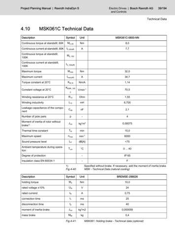
DOK-INDRV*-HMS01*UL***-IB07-EN-PRexroth IndraDrive Drive Controllers Power Sections HMS01Bosch Rexroth AG7/21Ratings and dimensions2Ratings and dimensionsUL ratings and .1N-W0036HMS01.1N-W0054HMS01.1N-W0070Listing in accordance with ULstandardUL 508CListing in accordance with CSAstandardC22.2 No. 14-10UL filesHMS01.1N-W0110E134201Pollution degree2Ambient temperature with nominaldataTamax C40Ambient temperature with reducednominal dataTamax red C55MassmkgDevice height1)Hmm440Device depth2)Tmm262Device width3)BmmMinimum distance on the top ofthe device4)dtopmm80Horizontal spacing on the device5)dhormm0Minimum distance on the bottomof the device6)dbotmm100Rated control voltage input7)UN3V24 20 %Rated power consumption controlvoltage input at UN38)PN3WShort circuit current ratingSCCRA rms42000Rated input voltage, power9)ULN nennVDC 254.750Rated input currentILNAOutput voltageUoutVOutput currentIoutA5,276,68501014,0751524,5Power dissipation at continuouscurrent and continuous DC buspower 485,00640,003 x AC 0.50012,121,3Field wiring material (material;conductor temperature; class)Output frequency range10)107,9435,0Cu; 60/75 C; 1foutHzPDiss contW0.1000165,00210,00420,00Last modification: 2014-09-261) 2) 3)4) 5) 6)7)Housing dimension; see also related dimensional drawingSee fig. "Air intake and air outlet at device"Observe supply voltage for motor holding brakesLSA Control S.L. www.lsa-control.com comercial@lsa-control.com ( 34) 960 62 43 01
8/21Bosch Rexroth AGDOK-INDRV*-HMS01*UL***-IB07-EN-PRexroth IndraDrive Drive Controllers Power Sections HMS01Ratings and dimensions8)HMS, HMD, HCS: Plus motor holding brake and control sec‐tion; HCS01: Incl. control section, plus safety option; KCU:Max. power consumption from 24V supply; KSM: Incl. motorholding brake (if available), plus power consumption of exter‐nally connected inputs/outputs, plus safety option; KMS: Plusmotor holding brake, plus power consumption of externallyconnected inputs/outputs, plus safety optionMains input L1, L2, L3 (for HMV and HCS only); For use on asolidly grounded wye source only.Depending on switching frequency which was set in parameterP‑0‑0001Plus dissipation of braking resistor and control section9)10)11)Tab. 2-1:HMS - UL ratings and dimensionsUL ratings and 1NW0210HMS01.1NW0300Listing in accordance with ULstandardUL 508CListing in accordance with CSAstandardC22.2 No. 14-10UL filesE134201Pollution degree2Ambient temperature with nominaldataTamax C40Ambient temperature with reducednominal dataTamax red C55Massmkgheight1)Hmm440Device depth2)Tmm262Device width3)BmmMinimum distance on the top ofthe device4)dtopmm80Horizontal spacing on the device5)dhormm0Minimum distance on the bottomof the device6)dbotmm100Rated control voltage input7)UN3V24 20 %Rated power consumption controlvoltage input at UN38)PN3WShort circuit current ratingSCCRA rms42000Rated input voltage, power9)ULN nennVDC 254.750Rated input currentILNAOutput 031,7020075350100167,0218290,03 x AC 0.500Last modification: 2014-09-26LSA Control S.L. www.lsa-control.com comercial@lsa-control.com ( 34) 960 62 43 01
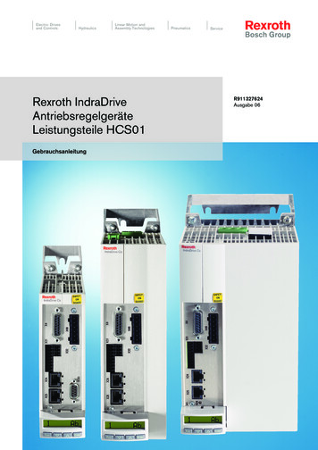
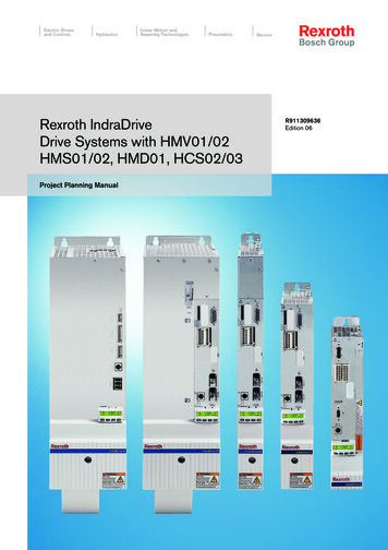
DOK-INDRV*-HMS01*UL***-IB07-EN-PRexroth IndraDrive Drive Controllers Power Sections HMS01Bosch Rexroth AG9/21Ratings and dimensionsDescriptionOutput currentSymbolUnitHMS01.1NW0150IoutA100,0Field wiring material (material;conductor temperature; class)Output frequency range10)Power dissipation at continuouscurrent and continuous DC buspower 1.1NW0350250,0Cu; 60/75 C; 1foutHzPDiss contW0.1000965,001570,001700,002750,00Last modification: 2014-09-261) 2) 3)4) 5) 6)7)8)11)Housing dimension; see also related dimensional drawingSee fig. "Air intake and air outlet at device"Observe supply voltage for motor holding brakesHMS, HMD, HCS: Plus motor holding brake and control sec‐tion; HCS01: Incl. control section, plus safety option; KCU:Max. power consumption from 24V supply; KSM: Incl. motorholding brake (if available), plus power consumption of exter‐nally connected inputs/outputs, plus safety option; KMS: Plusmotor holding brake, plus power consumption of externallyconnected inputs/outputs, plus safety optionMains input L1, L2, L3 (for HMV and HCS only); For use on asolidly grounded wye source only.Depending on switching frequency which was set in parameterP‑0‑0001Plus dissipation of braking resistor and control sectionABCdtopdbotdhorAir intakeAir outletMounting surface in control cabinetDistance topDistance bottomDistance horizontal9)10)Tab. 2-2:HMS - UL ratings and dimensionsDistancesFig. 2-1:Air intake and air outlet at deviceLSA Control S.L. www.lsa-control.com comercial@lsa-control.com ( 34) 960 62 43 01
10/21Bosch Rexroth AGDOK-INDRV*-HMS01*UL***-IB07-EN-PRexroth IndraDrive Drive Controllers Power Sections HMS01LSA Control S.L. www.lsa-control.com comercial@lsa-control.com ( 34) 960 62 43 01
DOK-INDRV*-HMS01*UL***-IB07-EN-PRexroth IndraDrive Drive Controllers Power Sections HMS01Bosch Rexroth AG11/21Overview of Documentations3Overview of Documentations3.1MotorsTitleKind of documentationRexroth IndraDyn Document typecode1)Material numberDOK-MOTOR*- R911 A Asynchronous Motors MAD / MAFProject Planning ManualMAD/MAF****-PRxx-EN-P295781H Synchronous Kit Spindle MotorsProject Planning ManualMBS-H******-PRxx-EN-P297895L Synchronous Linear MotorsProject Planning ManualMLF********-PRxx-EN-P293635S Synchronous Motors MSKProject Planning ManualMSK********-PRxx-EN-P296289T Synchronous Torque MotorsProject Planning ManualMBT********-PRxx-EN-P2987981)Tab. 3-1:In the document typecodes, "xx" is a wild card for the currentedition of the documentation (example: PR01 is the first editionof a Project Planning Manual)Documentations – OverviewLSA Control S.L. www.lsa-control.com comercial@lsa-control.com ( 34) 960 62 43 01
12/21Bosch Rexroth AGDOK-INDRV*-HMS01*UL***-IB07-EN-PRexroth IndraDrive Drive Controllers Power Sections HMS01LSA Control S.L. www.lsa-control.com comercial@lsa-control.com ( 34) 960 62 43 01
DOK-INDRV*-HMS01*UL***-IB07-EN-PRexroth IndraDrive Drive Controllers Power Sections HMS01Bosch Rexroth AG13/21Instructions for use4Instructions for use4.1Power Supply and Input VoltagePower sections HMS and HMD are only to be used in conjunction with listed(NMMS) DC power supply units like HMV, which are capable of delivering therated input current for the applicable power section. Branch circuit protectionhas to be provided externally according to the maximum values (voltage andcurrent), which are mentioned in the supply unit manual (Project PlanningManual).LSA Control S.L. www.lsa-control.com comercial@lsa-control.com ( 34) 960 62 43 01
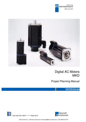
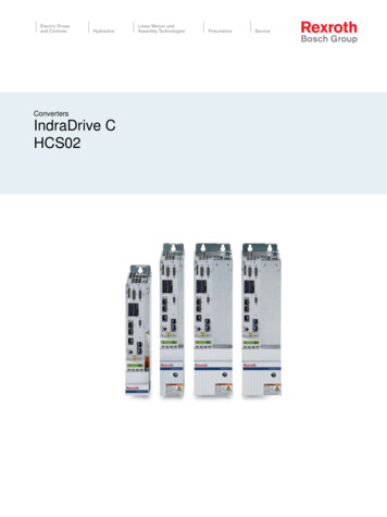
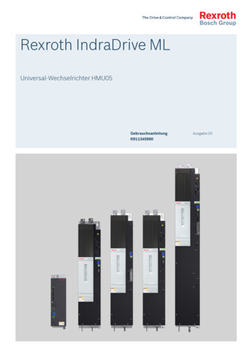
14/21Bosch Rexroth AGDOK-INDRV*-HMS01*UL***-IB07-EN-PRexroth IndraDrive Drive Controllers Power Sections HMS01Instructions for use4.2Connection4.2.1Connection diagramFig. 4-1:Connection Diagram HMSApart from the indicated connections, it is necessary to wire theBb contact at the control section for signaling the readiness foroperation of the drive controller (see Project Planning Manual"Rexroth IndraDrive Drive Controllers Control Sections").LSA Control S.L. www.lsa-control.com comercial@lsa-control.com ( 34) 960 62 43 01
DOK-INDRV*-HMS01*UL***-IB07-EN-PRexroth IndraDrive Drive Controllers Power Sections HMS01Bosch Rexroth AG15/21Instructions for useFor proper function of the motor thermal management connect the motorthermal sensor as described in the wiring diagram. Otherwise motor overtem‐perature sensing is not provided by the drive.For Rexroth motors with data memory in the motor encoder, such as MSK,the motor overload protection level is set automatically while connecting themotor to the drive. There is no adjustment necessary. Otherwise refer to theRexroth firmware documentation.4.2.2Connection pointsSymbols used to describe the connection pointsScrew terminal blockSpring terminalTab. 4-1:ThreadMax. connection crosssectionMax. tightening torqueSymbolsLSA Control S.L. www.lsa-control.com comercial@lsa-control.com ( 34) 960 62 43 01
16/21Bosch Rexroth AGDOK-INDRV*-HMS01*UL***-IB07-EN-PRexroth IndraDrive Drive Controllers Power Sections HMS01Instructions for useConnection pointX5HMS01mm2 (AWG)NmA 1)4,0 (10)0,6B 2)16,0 (6)1,7C 3)M66,51 16; 1 25; 1 352 16; 2 25; 2 35(1 6; 1 4; 1 2; 1 12 6; 2 4; 2 2; 2 1)M6D 4)6,51 16; 1 25; 1 35; 1 502 16; 2 25; 2 35; 2 50(1 6; 1 4; 1 2; 1 12 6; 2 4; 2 2; 2 1)M10E 5)201 16; 1 25; 1 35; 1 50; 1 70; 1 1202 16; 2 25; 2 35; 2 50; 2 70; 2 120(1 6; 1 4; 1 2; 1 1; 1 1/0; 1 2/0; 1 4/02 6; 2 4; 2 2; 2 1; 2 1/0; 2 2/0; 2 4/0)X6A, B, C, D, E1,5 (16)-24V, 0VA, B, C, D, EM66,5A, B4,0 (10)0,6C, D, EM66,0L , L-1)2)3)4)5)Tab. 4-2:A: HMS01.1N-W0020, ‑W0036B: HMS01.1N-W0054, ‑W0070C: HMS01.1N-W0110D: HMS01.1N-W0150, ‑W0210, ‑W0300E: HMS01.1N-W0350Connection pointsLSA Control S.L. www.lsa-control.com comercial@lsa-control.com ( 34) 960 62 43 01
DOK-INDRV*-HMS01*UL***-IB07-EN-PRexroth IndraDrive Drive Controllers Power Sections HMS01Bosch Rexroth AG17/21Service and support5Service and supportOur worldwide service network provides an optimized and efficient support.Our experts offer you advice and assistance should you have any queries.You can contact us 24/7.Service GermanyOur technology-oriented Competence Center in Lohr, Germany, is responsi‐ble for all your service-related queries for electric drive and controls.Contact the Service Hotline and Service Helpdesk under:Phone: 49 9352 40 5060Fax: 49 9352 18 p://www.boschrexroth.com/Additional information on service, repair (e.g. delivery addresses) and trainingcan be found on our internet sites.Service worldwideOutside Germany, please contact your local service office first. For hotlinenumbers, refer to the sales office addresses on the internet.Preparing informationTo be able to help you more quickly and efficiently, please have the followinginformation ready: Detailed description of malfunction and circumstances Type plate specifications of the affected products, in particular type co‐des and serial numbers Your contact data (phone and fax number as well as your e-mail ad‐dress)LSA Control S.L. www.lsa-control.com comercial@lsa-control.com ( 34) 960 62 43 01
18/21Bosch Rexroth AGDOK-INDRV*-HMS01*UL***-IB07-EN-PRexroth IndraDrive Drive Controllers Power Sections HMS01LSA Control S.L. www.lsa-control.com comercial@lsa-control.com ( 34) 960 62 43 01
DOK-INDRV*-HMS01*UL***-IB07-EN-PRexroth IndraDrive Drive Controllers Power Sections HMS01Bosch Rexroth AG19/21IndexIndex0 924V, 0V. 16AAdditional documentations. 11Appropriate use. 6CConnection diagram. 14Connection points. 15XX5.X6.X9.X14.X31.X32.X33.X34.X40.DDimensions. 7Distances. 9DocumentationMotors. 11Overview. 11Reference documentations. 11HHelpdesk. 17Hotline. 17IInstructions for use. 13LL , L-. 16MMotorDocumentation. 11PPower consumption. 7Project Planning Manuals. 11RRatings. 7Reference documentations. 11SSafety instructions. 3Service hotline. 17Support. 17UUseAppropriate. 6Instructions. 13VVoltage load capacity. 7LSA Control S.L. www.lsa-control.com comercial@lsa-control.com ( 34) 960 62 43 01161616161616161616
20/21Bosch Rexroth AGDOK-INDRV*-HMS01*UL***-IB07-EN-PRexroth IndraDrive Drive Controllers Power Sections HMS01NotesLSA Control S.L. www.lsa-control.com comercial@lsa-control.com ( 34) 960 62 43 01
DOK-INDRV*-HMS01*UL***-IB07-EN-PRexroth IndraDrive Drive Controllers Power Sections HMS01Bosch Rexroth AGNotesLSA Control S.L. www.lsa-control.com comercial@lsa-control.com ( 34) 960 62 43 0121/21
The Drive & Control CompanyBosch Rexroth AGElectric Drives and ControlsP.O. Box 13 5797803 Lohr, GermanyBgm.-Dr.-Nebel-Str. 297816 Lohr, GermanyTel. 49 9352 18 0Fax 49 9352 18 *UL***-IB07-EN-PLSA Control S.L. www.lsa-control.com comercial@lsa-control.com ( 34) 960 62 43 01
Components of the Rexroth IndraDrive system are products of category C3 (with limited availability) according to IEC 61800‑3. To ensure that this category (limit values) is maintained, suitable line filters must be used in the drive system.