Transcription
Geometric dimensioning &tolerancing (Part 1)KCEC 1101
Introduction Before an object can be built, completeinformation about both the size and shape ofthe object must be available. The exact shape of an object iscommunicated through orthographicdrawings, which are developed followingstandard drawing practices. The process of adding size information to adrawing is known as dimensioning thedrawing. In order that size information iscommunicated as clearly as possible,standard dimension practices have beenestablished.
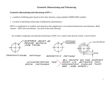
DIMENSIONING Geometrics is the science ofspecifying and tolerancing the shapesand locations of features on objects. Once the shape of a part is definedwith an orthographic drawings, thesize information is added also in theform of dimensions. Dimensioning a drawing also identifiesthe tolerance (or accuracy) requiredfor each dimension.
If a part isdimensionedproperly, then theintent of thedesigner is clearto both the personmaking the partand the inspectorchecking the part.
A fully defined part has three elements:– graphics,– dimensions, and– words (notes).
SIZE AND LOCATIONDIMENSIONS A well dimensioned part willcommunicate the size and locationrequirements for each feature.Communications is the fundamentalpurpose of dimensions. Parts are dimensioned based on twocriteria:– Basic size and locations of the features.– Details of a part's construction, formanufacturing.
On a drawing used in American industry, all dimensionsare in inches, unless otherwise stated. Most countries outside ofthe United States use themetric system of measure,or the international systemof units (SI), which is basedon the meter. The SI system is being usedmore in the United Statesbecause of global trade andmultinational companyaffiliationsOccasionally, a company willused dual dimensioning, thatis, both metric and Englishmeasurements on a drawing.
There are a number of terms important to theunderstanding of dimensioning practices.
A dimension is the numerical value thatdefines the size or geometric characteristicof a feature. A basic dimension is the numerical valuedefining the theoretically exact size of afeature. Basic dimension have no tolerance.
A reference dimension is the numericalvalue enclosed in parentheses provided forinformation only and is not used in thefabrication of the part.
A dimension line is the thinsolid line which shows theextent and direction of adimension.– Dimension lines are broken forinsertion of dimensionnumbers.Text height for dimensions is 3mm inthe metric system and .125" in thedecimal system.
Arrows are placed at the ends of dimensionlines to show the limits of the dimension. Arrows are uniform in size and style nomatter what the size of the drawing.
An extension line isthe thin solid lineperpendicular to adimension lineindicating whichfeature isassociated with thedimension. There isa visible gapbetween the featureand the end of anextension line.
A leader line is the thin solid line used toindicate the feature with which a dimension,note, or symbol is associated.
Limit of size: the largest acceptable size andthe minimum acceptable size of feature.– The value for the largest acceptable sizeÆ max material condition (MMC)– The value for the minimum acceptable sizeÆ least material condition (LMC)
Plus and minusdimensioning is theallowable positiveand negativevariance from thedimension specified A tolerance is the amount a particulardimension is allowed to vary.
What information is necessary tomake the object? Dimensions are used to describe thesize and location of features on partsfor manufacture. Dimensions should not be excessive,either through duplication ordimensioning a feature more than oneway.A size dimension might be theoverall width of the part or thediameter of a drilled hole.A location dimension mightbe length from the edge of theobject to the center of thedrilled hole.
Horizontal—the left tothe right distancerelative to the drawingsheet. Vertical—the up anddown distance relativeto the drawing sheet Diameter—the fulldistance across a circle,measured through thecenter. Radius—the distancefrom the center of an arcto any point on the arc,usually used on arcsless than half circles.Size dimension
Location & Orientationdimensions The location of features are based onthe three positions: horizontal,vertical, and angles
Coordinate dimension In rectangular coordinate dimensioning, abase line (or datum line) is established foreach coordinate direction, and alldimensions specified with respect to thesebaselines. This is also known as datum dimensioning,or baseline dimensioning. All dimensions are calculated as X and Ydistances from an origin point, usuallyplaced at the lower left corner of the part.
Datum dimensions are made based on acommon origin point, usually the lower leftcorner.
Datum dimensions can also be madewithout arrowheads and dimensionlines.
Tabular coordinate dimensioning involveslabeling each feature with a letter, and thenproviding information on size and location ina table.
Standard practices The guiding principal for dimensioninga drawing is clarity. To promote clarity, ANSI developedstandard practices for showingdimensions on drawings.
Standard practice:PlacementDimension placementdepends on the spaceavailable betweenextension lines.
Standard practice: Spacing The minimum distance from the object to the firstdimension is 10mm (3/8 inch). The minimum spacingbetween dimensions is 6mm (1/4 inch). Note that theseare minimum values and may be increased whereappropriate. There should be a visible gap between anextension line and the feature to which it refers.Extension lines should extend about 1mm (1/32 inch)beyond the last dimension line.
Standard practice:Grouping & staggering Dimensions should be grouped for uniformappearance as shown. As a general rule donot use object lines as part of yourdimension
Where there are severalparallel dimensions, thevalues should bestaggered.
Standard practice:Extension lines Extension lines are usedto refer a dimension to aparticular feature andare usually drawnperpendicular to theassociated dimensionline. Where space islimited, extension linesmay be drawn at anangle. Where angledextension lines are used,they must be parallel andthe associateddimension lines aredrawn in the direction towhich they apply.Angling extension lines
Extension lines should not cross dimension lines, andshould avoid crossing other extension lines wheneverpossible. When extension lines cross object lines orother extension lines, they are not broken. Whenextension lines cross or are close to arrowheads, theyare broken for the arrowhead.
When the location of thecenter of a feature isbeing dimensioned, thecenter line of the featureis used as an extensionline (Figure A). When a point is beinglocated by extensionlines only, the extensionslines must pass throughthe point (Figure B).
Standard practice:Limited length or area When it is necessary to define a limited length orarea that is to receive additional treatment (such asthe knurled portion of a shaft), the extent of thelimits may be shown by a chain line. The chain line is drawn parallel to the surface beingdefined. If the chain line applies to a surface ofrevolution, only one side need be shown.
Standard practice:Limited length or area When the limited area isbeing defined in a normalview of the surface, thearea within the chain lineboundary is sectionlined. Dimensions are addedfor length and locationunless the chain lineclearly indicates thelocation and extent of thesurface area.
Standard practice: Reading direction All dimension and note text must be oriented to beread from the bottom of the drawing (relative to thedrawing format). Placement of all text to be read from the bottom ofthe drawing is called unidirectional dimensioning.Aligned dimensions have text placed parallel to thedimension line with vertical dimensions read fromthe right of the drawing sheet.
Standard practice: View dimensioning Dimensions are to be kept outside of the boundariesof views of objects wherever practical. Dimensionsmay be place within the boundaries of objects incases where extension or leader lines would be toolong, or where clarity would be improved.
Standard practice: Not-to-scaledesignation If it is necessary to include a dimensionwhich is out of scale, the out of scaledimension text must be underlined.
Standard practice: Repetitive features The symbol X is usedto indicate the numberof times a feature is tobe repeated. Thenumber of repetitions,followed by thesymbol X and a spaceprecedes thedimension text.
Detail Dimensioning Holes are typicallydimensioned in a view whichbest describes the shape ofthe hole. Diameters must bedimensioned with thediameter symbol precedingthe numerical value. Whenholes are dimensioned with aleader line, the line must beradial. A radial line is one thatpasses through the center ofa circle or arc if extended.When it is not otherwiseclear that a hole extendscompletely through a part,the word THRU shall followthe numerical value.
Symbols may be usedfor spotface,counterbore, andcountersunk holes.These symbols alwaysprecede the diametersymbol. The depth symbol maybe used to indicate thedepth of a hole. The depth symbol isplaced preceding thenumerical value.
When the depth of ablind hole isspecified, it refersto the depth of thefull diameter of thehole.
When a chamfer orcountersink is placedin a curved surface,the diameter givenrefers to the minimumdiameter of thechamfer orcountersink. If the depth orremaining thickness ofmaterial for a spotfaceis not given, thespotface depth is thesmallest amountrequired to clean upthe material surface tothe specifieddiameter. Chamfers are dimensioned by providing either an angle and alinear dimension or by providing two linear dimensions. Chamfersof 45 degrees may be specified in a note.
Slotted holesmay bedimensionedany of severalways dependingon which is mostappropriate forthe application.
Keyseats are dimensionedin a particular way,because they presentsome unusual problems.
ASME standarddimension Dimensioning methodsused for various features(Fig A-B). The diameter is specifiedfor holes and blind holes.Blind holes are ones thatdo not go through the part.If the hole does not gothrough, the depth isspecified, preceded by thedepth symbol. Holes withno depth call out areassumed to go through(Fig C-F)
A counterbore symbol is placed before the diameter callout,and the depth of the counterbore is added with a depthsymbol. If a depth is stated, it is a counterbore. If not, then itis a spotface. The full note shows the diameter of the through hole followedby the diameter of the counterbore then the depth of thecounterbore. The spotface has the same specification as the counterbore,except that the depth is not specified.
A countersink symbol is placed with a diameter ofthe finished countersink, followed by the anglespecification. The reason the depth is not given isthat the resultant diameter is much easier tomeasure.
If a full circle or an arc of more than half of a circleis being dimensioned, the diameter is specified,preceded by the diameter symbol which is theGreek letter phi. If the arc is less than half of a circle,then the radius is specified and it ispreceded by an R. Concentric circlesshould be dimensioned in thelongitudinal view whenever practical.
Radii are dimensioned with the radius symbol preceding thenumerical value. The dimension line for radii shall have a single arrowheadtouching the arc. When there is adequate room the dimensionis placed between the center of the radius and the arrowhead.When space is limited, a radial leader line is used. When thecenter of an arc is not clearly defined by being tangent toother dimensioned features on the object, the center of thearc is noted with a small cross.
If the center of an arc interferes with another viewor is outside of the drawing area, foreshorteneddimension lines may be used.
When a radius is dimensioned in a viewwhere it does not appear true shape theword TRUE appears preceding the radiussymbol.
There are standards that apply directly toeach size thread. ANSI Y14.6 is a completedefinition of all of the inch series threads.Local notes are used to identify threadtypes and dimensions. For threaded holes, thenote should be placedon the circular view.For external threads,the note is placed onthe longitudinal view ofthe thread.
Dimensioning techniques:Correct contour dimension Dimensioning is accomplished by adding size and locationinformation. One dimensioning technique is called contourdimensioning, because the contours or shapes of the object aredimensioned in their most descriptive view. For example, the radius of a arc would be dimensioned where itappears as an arc and not as a hidden feature
Dimensioning techniques:Avoid over-dimensioningDouble dimensioning of a feature is not permitted.
Dimensioning techniques:Dimension the most descriptive viewDimensions should be placed in theview which most clearly describes thefeature being dimensioned.
Will continue to GDT 2
DIMENSIONING Geometrics is the science of specifying and tolerancing the shapes and locations of features on objects. Once the shape of a part is defined with an orthographic drawings, the size information is added also in the form of dimensions. Dimensioning a dra