Transcription
Geometric Dimensioningand Tolerancingfor Mechanical DesignInstructors’ GuideContents1.2.3.4.5.Course CalendarLecture TopicsStudy Guide and Problem AnswersMidterm and Final ExamMidterm and Final Exam answersRev. 10/12/2020Geometric Dimensioning and Tolerancing for Mechanical Design2Instructors’ Guide
Course CalendarWeekDate1st Weekly Meeting2nd Weekly Meeting3rd Weekly Meeting1Admin. & OverviewLecture 1Ch. 1Lecture 2Ch. 22Lecture 3Ch. 3Lecture 4Ch. 3Lecture 5Ch. 33Lecture 6Ch. 4Lecture 7Ch. 4Lecture 8Ch. 44Lecture 9Ch. 5Lecture 10Ch. 5Lecture 11Ch. 55Lecture 12Ch. 5Lecture 13Ch. 5Lecture 14Ch. 66Lecture 15Ch. 6Lecture 16Ch. 6Lecture 17Ch. 7Lecture 18Ch. 7Midterm Review7First Midterm Exam8Lecture 19Ch. 7Lecture 20Ch. 7Lecture 21Ch. 89Lecture 22Ch. 8Lecture 23Ch. 8Lecture 24Ch. 810Lecture 25Ch. 9Lecture 26Ch. 9Lecture 27Ch. 911Second Midterm ExamLecture 28Ch. 1012Lecture 29Ch. 10Lecture 30Ch. 11Lecture 31Ch. 1113Lecture 32Ch. 11Lecture 33Ch. 12Lecture 34Ch. 1214Lecture 35Ch. 12Lecture 3615WeekDateMidterm ReviewAppend. ALecture 37Append. AFinal ReviewFinal ReviewFinal Exam1st Weekly Meeting2nd Weekly Meeting3rd Weekly Meeting1Admin. & OverviewLecture 1Ch. 1Lecture 2Ch. 32Lecture 3Ch. 3Lecture 4Ch. 3Lecture 5Ch. 43Lecture 6Ch. 4Lecture 7Ch. 5Lecture 8Ch. 54Lecture 9Ch. 6Lecture 10Ch. 6Lecture 11Ch. 6Lecture 12Ch. 75Midterm ExamMidterm Review6Lecture 13Ch. 7Lecture 14Ch. 7Lecture 15Ch. 87Lecture 16Ch. 8Lecture 17Ch. 8Lecture 18Ch. 88Lecture 19Ch. 9Lecture 20Ch.10Lecture 21Ch.119Lecture 22Ch.11Lecture 23Ch.12Lecture 24Ch.1210Lecture 25Ch. 12Final ReviewGeometric Dimensioning and Tolerancing for Mechanical Design3Final ExamInstructors’ Guide
Lecture TopicsNo.12345678Topics1. IntroductionA. What is Geometric Dimensioning and TolerancingB. When should GD&T be used?C. Advantages of GD&T over coordinate dimensioning and tolerancing1. The cylindrical tolerance zone2. The maximum material condition3. Datums specified in order of precedence2. Dimensioning and Tolerancing FundamentalsA. Fundamental drawing rulesB. Units of linear measurementC. Specifying linear dimensionsD. Specifying linear tolerancesE. Interpreting dimensional limitsF. Specifying angular dimensionsG. Specifying angular tolerancesH. Dimensioning and Tolerancing for CAD/CAM database models3. Symbols, Terms, and RulesA. Geometric characteristic symbolsB. The datum feature symbolC. The feature control frameD. Reading the feature control frameE. Other symbols used with geometric tolerancingF. TermsG. General rules1. Rule #12. Rule #23. Pitch diameter rule4. DatumsA. DefinitionB. Application of datumsC. Immobilization of a partD. Datum feature selectionE. Datum feature identificationF. Inclined datum featuresG. Cylindrical datum featuresH. Establishing datum featuresI. Irregular features of sizeJ. Common datum featuresK. Partial datum featuresL. Datum targetsGeometric Dimensioning and Tolerancing for Mechanical Design4Instructors’ Guide
9101112131415161718195. Form controlsA. Flatness1. Definition2. Specifying flatness tolerance3. Specifying flatness of a median plane4. Unit flatnessB. Straightness1. Definition2. Specifying straightness of a surface3. Specifying straightness of a median line4. Unit straightnessC. Circularity1. Definition2. Specifying Circularity ToleranceD. Cylindricity1. Definition2. Specifying Cylindricity ToleranceE. Free state variation1. Average diameter2. Free state3. Restrained condition6. OrientationA. Perpendicularity1. Definition2. Specifying perpendicularity of a flat surface3. Tangent plane4. Specifying perpendicularity of an axisB. Parallelism1. Definition2. Specifying parallelism of a plane surface3. Specifying parallelism of an axisC. Angularity1. Definition2. Specifying angularity of a plane flat surface3. Specifying angularity of an axis7. Position, GeneralA. DefinitionB. The tolerance of positionC. Specifying the position tolerance at1. Regardless of feature size (RFS)2. Maximum material condition (MMC)D. Datum features of size at regardless of material boundary (RMB)E. Datum features of size at maximum material boundary (MMB)F. MMB explained in more detailG. Least material conditionGeometric Dimensioning and Tolerancing for Mechanical Design5Instructors’ Guide
202122232425262728293031323334H. Boundary conditionsI. “0” positional tolerancing at MMC8. Position, LocationA. Floating and fixed fastenersB. Projected tolerance zonesC. Multiple patterns of featuresD. Composite positional tolerancingE. Multiple single-segment positional tolerancingF. Nonparallel holesG. Counterbored holesH. Noncircular featuresI. Symmetrical features9. Position, CoaxialityA. DefinitionB. Comparison between coaxiality controlsC. Specifying coaxiality at MMCD. Composite control of coaxial featuresE. Coaxial features controlled without datum referencesF. Tolerancing a plug and socket10. RunoutA. DefinitionB. Circular runoutC. Total runoutD. Specifying runout and partial runoutE. Multiple datum featuresF. Face and diameter datum featuresG. Geometric control to refine datum featuresH. The relationship between feature surfacesI. Inspecting runout11. ProfileA. DefinitionB. Specifying profile toleranceC. The application of datum featuresD. A radius refinement with profileE. Combining profile tolerances with other geometric controlsF. CoplanarityG. Profile of a conical featureH. Composite profile tolerancingI. Multiple single-segment profile tolerancingJ Inspection12. A Strategy for Tolerancing PartsA. Feature of sizes located to plane surface featuresB. Feature of sizes located to feature of sizesC. A pattern of features located to a second pattern of featuresGeometric Dimensioning and Tolerancing for Mechanical Design6Instructors’ Guide
35363713. Graphic AnalysisA. Advantages of graphic analysisB. The accuracy of graphic analysisC. Analysis of a composite geometric toleranceD. Analysis of a pattern of features controlled to a datum feature of sizeAppendix A. Concentricity & SymmetryA. Concentricity1. The definition of concentricity2. Specifying concentricity3. Applications of concentricityB. Symmetry1. The definition of symmetry2. Specifying symmetry3. Applications of symmetryGeometric Dimensioning and Tolerancing for Mechanical Design7Instructors’ Guide
Chapter 1Introduction toGeometric Dimensioning and TolerancingChapter ReviewPage 7ASME Y14.5–20181.is the current, authoritative reference documentthat specifies the proper application of GD&T.2. GD&T is a symbolic language used to specify thesizeandshape,locationform,,orientationof features on a part.actual relationship3. Features toleranced with GD&T reflect thebetween mating parts.4. GD&T was designed to insure the proper assembly ofmating parts, to improvequality5. Geometric tolerancing allows the maximum availableconsequently, the mosteconomical6. Plus or minus tolerancing generates7.GD&T, and reducecost.toleranceand,parts.rectangulartolerance zone.generates a cylindrical shaped tolerance zone to control an axis.8. If the distance across a square tolerance zone is .005 or a total of .010, what is the approximatedistance across the diagonal? .007 or .014Geometric Dimensioning and Tolerancing for Mechanical Design8Instructors’ Guide
9. Thecylindrical tolerance zonedefines a uniform distance from trueposition to the tolerance zone boundary.10. Bonus tolerance equals the difference between the actual mating envelope size and themaximum material condition.datum reference frame11. While processing, a rectangular part usually rests against aconsisting of three mutually perpendicular intersecting planes.Chapter 2Dimensioning and Tolerancing FundamentalsChapter ReviewPage 151.Each feature must be atoleranced. Those dimensions specifically identified asreference, maximum, minimum, or stock do not require the application of a tolerance.2.Dimensioning and tolerancing must bethe3.completeso there is a full understanding ofcharacteristicsof each feature.Dimensions must be selected and arranged to suite the function and mating relationship of a part andmust not be subject to more than oneinterpretation4.The drawing should define a part without specifying5.Animplied 90 anglemanufacturing.methods.always applies where centerlines and lines depictingfeatures are shown on orthographic views at right angles and no angle is specified.Animplied 90 basic anglealways applies where center lines of features orsurfaces shown at right angles on an orthographic view are located or defined by basic dimensions andno angle is specified.7. Unless otherwise specified, all dimensions and tolerances are applicable at68 F (20 C).Compensation may be made for measurements made at other temperatures.8. Unless otherwise specified, all dimensions and tolerances apply in afree state conditionexcept for restrained non-rigid parts.Geometric Dimensioning and Tolerancing for Mechanical DesignInstructors’ Guide6.9
9.Unless otherwise specified, all tolerances and datum features apply for the fulllengthandwidth10. Dimensions and tolerances apply only at thedepthof the feature.drawing levelwhere they arespecified.inch11. Units of linear measurement are typically expressed either in themetricsystem or thesystem.12. Where specifying decimal inch dimensions, azerois never placed before the decimalpoint for values less than one inch.13. What are the three types of direct tolerancing methods?Limit, Plus and Minus, and Geometric tolerancing14. Where inch tolerances are used, a dimension is specified with the same number of decimal places as itstolerance.15. Where a unilateral tolerance is specified and either the plus or minus limit is zero, its dimension andzero value must have thevalue must have thesame number of decimal placesopposite signas the other limit and the 0of the nonzero value.16. For decimal inch tolerances, where bilateral tolerancing or limit dimensioning and tolerancing is used,both valueshave the same number of decimal places.17. Dimensional limits are used as if aninfinite number of zerosfollowedthe last digit after the decimal point.18. Angular units of measurement are specified either indegreeordegrees and decimal parts of adegrees, minutes, and seconds.19. What two dimensions are not placed on the field of the drawing?90 angles and zero dimensions20. Dimensioning and Tolerancing for CAD/CAM Database Models. Dimensioning and tolerancing shall becomplete so there is full understanding of the characteristics of each feature. Values may be expressed inan engineering drawing or in aCAD product definition data set specified in ASMEY14.41.Geometric Dimensioning and Tolerancing for Mechanical Design10Instructors’ Guide
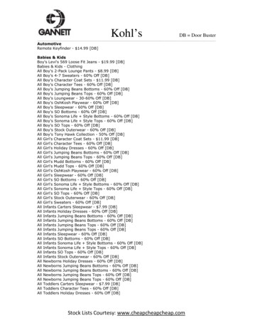
Chapter 3Symbols, Terms, and RulesChapter ReviewPage 461.2.formWhat type of geometric tolerances has no datum features?What is the name of the symbol used to identify physical features of a part as a datum feature and mustnot be applied to centerlines, center planes, or axes?datum feature symbolI, O, & Q3.Datum feature identifying letters may be any letter of the alphabet except?4.If the datum feature symbol is placed in line with a dimension line or on a feature control frameassociated with a feature of size, the datum feature is what kind of feature?a feature of size5.One of the 12 geometric characteristic symbols always appears in thefirstcompartment of the feature control frame.tolerance6.The second compartment of the feature control frame is the7.The tolerance is preceded by a diameter symbol only if the tolerance zone is8.Datum features are arranged in order ofprecedencesection.cylindrical.Figure 3-36 Position feature control frame9.Read the feature control frame in Fig. 3-361. The position tolerance requires that2. The axis of the controlled featureGeometric Dimensioning and Tolerancing for Mechanical Design11Instructors’ Guide
3. Must lie within a cylindrical tolerance zone4. 010 in diameter5. At maximum material condition (MMC)6. Oriented and located with basic dimensions to a datum reference frameestablished by datum feature A, datum feature B at its maximum materialboundary, and datum feature C at its maximum material boundary.10. The all around and between symbols are used with what control?11. The all over symbol consists of two smallthe profile controlconcentric circlesplaced atthe joint of the leader connecting the feature control frame to the feature.12. Thecontinuous featuresymbol specifies that a group of two or moreinterrupted features of size are to be considered one single feature of size.13. If no depth or remaining thickness is specified, the spotface is theminimumdepth necessary to clean up the surface of the specified diameter.14. Theindependencysymbol indicates that perfect form of a feature of size at MMCor LMC is not required.15. Theunequally disposedsymbol indicatesthat the profile tolerance is unilateral or unequally disposed about the true profile.16. Thedatum translationsymbol indicates that a datum feature simulatoris not fixed and is free to translate within the specified geometric tolerance.17. Theactual mating envelopeis a similar, perfect, feature(s) counterpart of smallest size that can be contracted about an externalfeature(s) or largest size that can be expanded within an internal feature(s) so that it coincides with thesurface(s) at its highest points.18. A theoretically exact dimension is called abasic dimension.19. What is the theoretically exact point, axis, line, plane, or combination thereof derived from thetheoretical datum feature simulator called?a datumGeometric Dimensioning and Tolerancing for Mechanical Design12Instructors’ Guide
20. Adatum featureis a feature that is identified with either adatum feature symbol or a datum target symbol.21. Adatum feature simulatoris thephysical boundary used to establish a simulated datum from a specified datum feature.22. Adatum reference frameconsists of three mutuallyperpendicular intersecting datum planes and three mutually perpendicular axes at the intersection ofthose planes.23. What is the name of a physical portion of a part, such as a surface, pin, hole, tab, or slot?A feature24. A regular feature of size is a feature, which is associated with a directly toleranced dimension and takesone of the following forms:a) A cylindrical surfaceb) A set of two opposed parallel surfacesc) A spherical surfaced) A circular elemente)A set of two opposed parallel elementsGeometric Dimensioning and Tolerancing for Mechanical Design13Instructors’ Guide
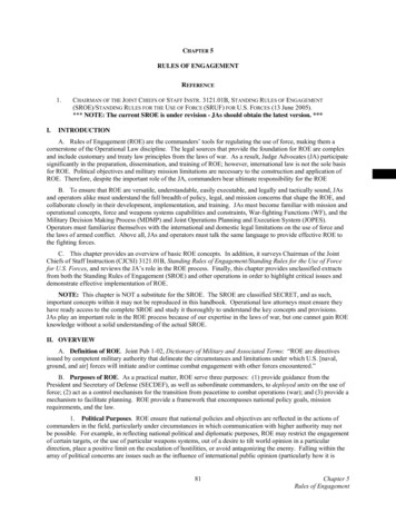
Figure 3-37 Geometric characteristic symbols25. Write the names and geometric characteristic symbols where indicated in Fig. 3-37.Geometric Dimensioning and Tolerancing for Mechanical Design14Instructors’ Guide
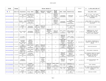
All AroundFree StateFAll OverIndependencyIBetween)Projected Tolerance ZonePNumber of PlacesXTangent PlaneTContinuous FeatureCFUnequally Disposed pth/Deep Radius, ControlledCRDiameterØSpherical RadiusSRDimension, Basic1.000Spherical DiameterSØDimension, Reference(60)SquareDimension Not To Scale15Statistical ToleranceST!Datum TargetØ.500A1Dimension OriginMovable Datum TargetDatum TranslationArc Length110Target PointConical Taper@Dynamic ProfileSlope#From - ToA1Figure 3-38 Geometric tolerancing symbols26. Draw the indicated geometric tolerancing symbols in the spaces on Fig. 3-38.Geometric Dimensioning and Tolerancing for Mechanical Design15Instructors’ Guide
27. Themaximum material conditionis the condition in which a feature of sizecontains the maximum amount of material within the stated limits of size.28. Theleast material conditionis the condition in which a feature of sizecontains the least amount of material within the stated limits of size.29. What kind of feature always applies at MMC/MMB, LMC/LMB, or RFS/RMB?A feature of size30. The maximum material condition modifier specifies that the tolerance applies at themaximum material conditionsize of the feature.31. The MMC modifier indicates that the tolerance applies at the MMC size of the feature and that abonus32.tolerance is available as the size of the feature departs from MMC towards LMC.Bonustolerance is the positive difference or the absolute value between theactual mating envelope and the MMC.33. The total positional tolerance equals the sum of thetolerance and thebonuspositionaltolerance.Refer to Fig. 3-39 to answer questions 34 through 41.HolePin34.What is the MMC?.515.50035.What is the LMC?.540.49536.What is the geometric tolerance?.010.00537.What material condition modifier is specified?MMCMMC38.What datum feature(s) control(s) perpendicularity?AA39.What datum feature(s) control(s) location?B&CB&CGeometric Dimensioning and Tolerancing for Mechanical Design16Instructors’ Guide
Figure 3-39 Refer to this drawing for questions 34 through 41Internal Feature 10.025.535.515.020.010.030LMC .540.515.025.010.035Table 3-3 Total positional tolerance for holes40. Using the drawing in Fig. 3-39, complete Table 3-3.Geometric Dimensioning and Tolerancing for Mechanical Design17Instructors’ Guide
External Feature etricToleranceMMCBonusMMC LMC .495.500.005.005.010Table 3-4 Total positional tolerance for pins41. Using the drawing in Fig. 3-39, complete Table 3-4.42. Amaterial condition modifieris specified in a feature control frame when it isassociated with the geometric tolerance of a feature of size or a datum feature of size.43. TheRegardless of feature sizemodifier indicates that the specified geometric toleranceapplies at any increment of size of the actual mating envelope of the unrelated feature of size.44. Theresultant conditionof a feature of size specified with anMMC modifier is the single worst-case boundary generated by the collective effects of the LMC limitof size, the specified geometric tolerance, and the size tolerance.True position45.is the theoretically exact location of a featureof size, as established by basic dimensions.True profile46.is the theoretically exact profile on a drawingdefined by basic dimensions or a digital data file.47. TheVirtual conditionof a feature of size specified withan MMC modifier is a constant boundary generated by the collective effects of the considered feature’sMMC limit of size and the specified geometric tolerance.48. For an individual regular feature of size, no element of the feature shall extend beyond the maximummaterial condition boundary (envelope) of perfect form.This statement is the essence of Rule #1Geometric Dimensioning and Tolerancing for Mechanical Design18Instructors’ Guide
49. The local form tolerance increases as the actual local size of the feature departs from MMC towardLMC50. If features on a drawing are shown coaxial, or symmetrical to each other and not controlled forlocationororientation, the drawing is incomplete.51. If there is no orientation control specified for a rectangle on a drawing, the perpendicularity iscontrolled, not by the sizetolerance, but by theangularity52. Rule #2 states thatsize andtolerance.RFSRMBautomatically applies, to individual tolerances of feature ofautomatically applies to datum features of size.53. Each tolerance of orientation or position and datum reference specified for a screw thread applies to theaxis of thepitch diameter.54. Each geometric tolerance or datum reference specified for gears and splines must designate the specificfeature at which each applies such asMAJOR DIA, PITCH DIA, or MINOR DIAProblemsPage 55Figure 3-40 Feature control frames with material condition symbols: Prob. 1.1.A.Read the complete tolerance in each feature control frame in Fig. 3-40, and write it below (Datumfeature A is a feature of size).1. The position tolerance requires that2. The axis of the controlled feature3. Must lie within a cylindrical tolerance zone4. .005 in diameter5. At RFS6. Oriented and located with basic dimensions to datum feature A at RMBGeometric Dimensioning and Tolerancing for Mechanical Design19Instructors’ Guide
B.1. The position tolerance requires that2. The axis of the controlled feature3. Must lie within a cylindrical tolerance zone4. .005 in diameter5. At MMC6. Oriented and located with basic dimensions to datum feature A at MMBFigure 3-41 Geometric dimensioning and tolerancing terms: Prob. 2.2.Place each letter of the items on the drawing in Fig. 3-41 next to the most correct term below.CABFeatureGBasic DimensionJFeature control frameMMCFDatum FeatureDTrue PositionLMCEFeature of SizeHDatum feature symbolGeometric Dimensioning and Tolerancing for Mechanical Design20Instructors’ Guide
Chapter 4DatumsChapter ReviewPage 721.Datums are theoretically perfect2.Datums establish thepoints, axes, lines, planes, or a combination thereof.originfrom which the location or geometric characteristic offeatures of a part are established.feature simulators.3.Datums are assumed to exist in and be simulated by datum4.A datum reference frame consists of three mutually perpendicularmutually perpendicular5.axesand threeat the intersection of those planes.A part is oriented and immobilized relative to the three mutually perpendicular intersecting datumplanes of the datum reference frame in a selected order of6.planesprecedenceThe primary datum feature contacts the datum reference frame with a minimum of.threepoints of contact that are not in a straight line.7.Datum features are specified in order of precedence as they appear from left to right in thefeature control frame.8.Datum feature letters need not be inalphabetical9.The primary datum feature controlsthe orientation of the partorder.10. When selecting datum features, the designer should consider features that are:Functional surfaces, mating surfaces, readily accessible surfaces, andsurfaces that allow repeatable measurements11. Datum features must be identified withordatum targets.datum feature symbolsand specified in a feature control frame.12. Datum feature symbols must not be applied tocenterlines, center planes, or axesGeometric Dimensioning and Tolerancing for Mechanical Design21.Instructors’ Guide
13. One method of tolerancing datum features at an angle to the datum reference frame is to place a datumfeature symbol on theinclined surfaceandcontrol that surface with an angularity tolerance and a basic angle.14. A cylindrical datum feature is always associated with twotheoretical planesmeeting at right angles at its datum axis.15. The two kinds of features specified as datum features are:Plane flat surfaces and features of size16. Datum features of sizes may apply atregardless of material boundary, maximummaterial boundary, or least material boundary17. Where datum features of sizes are specified at RMB, the processing equipment must makephysical contactwith the datum features.18. Where features of sizes are specified at MMB, the size of the processing equipment has is equal to itsvirtual condition with respect to the previous datum feature.Figure 4-20 Datum feature of size: Questions 19 through 24.Geometric Dimensioning and Tolerancing for Mechanical Design22Instructors’ Guide
(Refer to Fig. 4-20 to answer questions 19 through 24.)19. The 2-hole pattern is perpendicular to what datum feature?Datum feature A20, The 2-hole pattern is located to what datum feature?Datum feature BØ 6.03021. If inspected with a gage, what is the diameter of datum feature B on the gage?22. If inspected with a gage, what is the diameter of the 2 pins on the gage?Ø.50023. If datum feature B had been specified at RFS, explain how the gage would be different.Datum feature B would have to be a variable diameter like a chuck to makephysical contact with the outside diameter.24. If datum feature B had been specified as the primary datum at RFS, explain how the gage would bedifferent.Datum feature B would not only have to be a variable diameter, such as achuck, to make physical contact with the outside diameter, but the outsidediameter of the part, datum feature B, must align with the gage as well.25. If a datum feature symbol is in line with a dimension line, the datum feature is thefeature of sizemeasured by the dimension.26. Where more than one datum feature is used to establish a single datum, thedatum reference lettersand appropriatemodifiersare separated by a dash and specified in one compartment of the feature control frame.27. Where cylinders are specified as datum features, the entire surface of the feature is considered to be thedatum feature.28. If only a part of a feature is required to be the datum feature, aheavy chain lineis drawn adjacent to the surface profile and dimensioned with basic dimensions.29. Datum targets may be used to immobilize parts with30. Costly manufacturing and inspectionuneven or irregular surfacestoolingis required to process a part with datum targets.Geometric Dimensioning and Tolerancing for Mechanical Design23Instructors’ Guide
ProblemsPage 76Figure 4-21 Placement of datum feature symbols: Prob. 1.1.Attach the appropriate datum feature symbols on the drawing in Fig. 4-21.Geometric Dimensioning and Tolerancing for Mechanical Design24Instructors’ Guide
Figure 4-22 Placement of datum references in a feature control frames: Prob. 2.2.Provide the appropriate datum feature symbols and complete the feature control frames on the drawingin Fig. 4-22.(Two solutions suggested.)Geometric Dimensioning and Tolerancing for Mechanical Design25Instructors’ Guide
Figure 4-23 Datum features of size at MMB and RMB: Prob. 3.3.Complete the feature control frames with datum references and material condition modifiers to reflectthe drawings in Fig. 4-23.Geometric Dimensioning and Tolerancing for Mechanical Design26Instructors’ Guide
Figure 4-24 Datum features located to the center planes of the drawing: Prob. 4.4.Specify the appropriate datum feature symbols to locate the four-hole pattern to the center planes of thedrawing in Fig 4-24.Geometric Dimensioning and Tolerancing for Mechanical Design27Instructors’ Guide
Figure 4-25 Specifying datum references and datum feature symbols: Probs. 5 and 6.5.Specify the appropriate datum feature symbols and complete the feature control frames in the datumexercise in Fig. 4-25.(One solution. Explore other possibilities.)Geometric Dimensioning and Tolerancing for Mechanical Design28Instructors’ Guide
Chapter 5FormChapter ReviewPage 93features1.Form tolerances are independent of all other.2.No3.The form of individual features of size is automatically controlled by thedatumsapply to form tolerances.size tolerance, Rule #14.Where the size tolerance does not sufficiently control the form of a feature, a form tolerance may bespecified as a5.refinement.All form tolerances are surface controls except forflatness of a median plane and straightness of a median line6.Nocylindrical tolerance zonesor.material condition symbolsare appropriate for surface controls.7.Flatness of a surface or derived median plane is a condition where all line elements of that surface arein one8.plane.In a view where the surface to be controlled with a flatness tolerance appears as aa feature control frame is attached to the surface with a9.leader or extension line,.flatness symbolThe feature control frame controlling flatness contains aand alinenumerical tolerance.10. The surface being controlled for flatness must lie betweentwo parallel planesseparated by the flatness tolerance. In addition, the feature must fall within thesize tolerance.parallel11. The flatness tolerance zone does not need to beGeometric Dimensioning and Tolerancing for Mechanical Design29to any other surface.Instructors’ Guide
12. The feature of size may not exceed theboundary of perfect form at MMCFigure 5-15 Specifying flatness: Question 13.13. Specify a flatness tolerance of .006 in a feature control frame to the top surface of the part in Fig. 5-15.14. Draw a feature control frame below with an overall flatness of .015 and a unit flatness of .001 persquare inch.15. When verifying flatness, the feature of size is first measured to verify that it falls within thesize limits.parallelism16. The surface is adjusted with jackscrews to remove anyerror.17. Flatness verification is achieved by measuring the surface in all directions with adial indicator18. Straightness is a condition wherean element of a surface, or a derived median line,is a straight line.19. In a view where the line elements to be controlled appear as aa feature control frame is attached to the surface with a20. Straightness tolerance is a refinement of theand must be less than thelineleader or an extension linesize tolerance, Rule #1size toleranceGeometric Dimensioning and Tolerancing for Mechanical Design30,,.Instructors’ Guide
Actual Part SizeStraightness led ByRule #1Table 5-6 Review question 2121. Complete Table 5-6 specifying the straightness tolerance and what controls it for the drawing in Fig. 5-6.22. The measurement of surface variation for straightness is performed similar to the measurement forflatness23. Each line element is.independentof every other line element.24. When a feature control frame with a straightness tolerance is associated with a size dimension, thestraightness tolerance applies tothe median line25. While each actual local size must fall within the.size tolerance,the feature controlled with straightness of a median line may exceed theboundary of perfect format maximum material condition.26. A straightness control of a median line will allow the feature to violateRule #1.27. If specified at MMC, the total straightness tolerance of a median line equals the tolerance in the featurecontrol frame plus anybonus toleranceGeometric Dimensioning and Tolerancing for Mechanic
Oct 12, 2020 · Geometric Dimensioning and Tolerancing for Mechanical Design Instructors’ Guide 8 Chapter 1 Introduction to Geometric Dimensioning and Tolerancing Chapter Review Page 7 1. ASME Y14.5–2018 is the current, authoritative reference document that specifies the proper application of GD&