Transcription
WHAT IS GEOMETRICDIMENSIONING &TOLERANCING?orHelp! My parts don’t fit
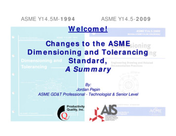
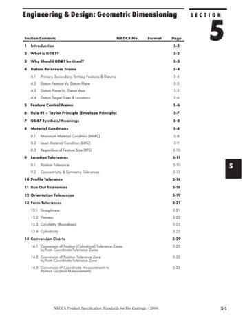
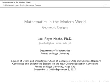
I Need a Part !Example of a Simple PinPin must fit into a hole with aØ.260 inch mating envelope
The Produce Development Cycle(In a Nutshell) Identify NeedRequirementsDesignManufactureVerificationNeed Satisfied ( )
The Design
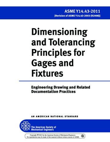
What Can Go Wrong? Limit dimensions were used to define part Controls diametrically opposed elements onlyPin can be lobed and still meet thisrequirementThere is no form control for “roundness”There is also no form control for “straightness”
Help! My Part Doesn’t Fit!NO FORM CONTROL!
Other Limitations of LimitDimensioning Inconsistentinspection resultsDependent onorientationRelies on impliedoriginsNot cool!
Other Limitations of LimitDimensioning (con’t) Overly RestrictiveIf requirement is axialalignment within .014Plus-minus tolerancemust be .005Results in a squaretolerance zone
How Do I Get What I Want?Using Limit Dimensions Build the part yourself Usethe mating part as a gage Limited only by your machining skills andequipment Work closely with the manufacturer Provideaccess to your setup Communication is key Limited by location and accessibility (are they onthe same continent and speak English?) Find an alternate way to describe your part
Chances for SuccessUsing Limit DimensionsHIGHSuccess ScaleVERY, VERY LOW
Another Option is to Use GeometricDimensioning & Tolerancing (GD&T) Reference ASMEY14.5M-1994 onyour drawingFor the pin, that’sall you need!Problem solved.
What is GD&T? “The purpose of GD&T is to describe the engineering intent ofparts and assemblies” –ASME Y14.5M-1994GD&T is covered by several standards ASME Y14.5 - 2009 Dimensioning and TolerancingASME Y14.5M-1994 Dimensioning and TolerancingASME Y14.5.1M-1994 Mathematical Definition of Dimensioning and Tolerancing PrinciplesISO 286-1:1988 ISO system of limits and fits — Part 1: Bases of tolerances, deviations and fitsISO 286-2:1988 ISO system of limits and fits — Part 2: Tables of standard tolerance grades and limitdeviations for holes and shaftsISO 1101:2005 Geometrical Product Specifications (GPS) — Geometrical tolerancing — Tolerancing of form,orientation, location and run-outISO 5458:1998 Geometric Product Specifications (GPS) — Geometrical tolerancing — Positional tolerancingISO 5459:1981 Technical drawings — Geometrical tolerancing — Datums and datum-systems forgeometrical tolerancesASME Y14.5M-1994 will be discussed here Still widely used in American Industry
ASME Y14.5M-1994 Developed and published by the AmericanSociety of Mechanical EngineersReaffirmed in 1999 and 2004Replaced by ASME Y14.5M-2009Committee members are selected fromindustry and volunteer their time (not paid)
Key Concepts of GD&T Controls size, form, orientation, and location betweenfeaturesA feature can be a hole, surface, boss, radius, etc. It can have either size or no sizeFeatures of size have opposed elementsDefines feature material conditions Maximum material condition (MMC) Least material condition (LMC) Variation of size where the feature contains the most materialVariation of size where the feature contains the least materialTolerance allocation can be based on material conditionUse of datums and basic dimensions to establish tolerancezones
Rule #1(aka Envelope Rule or Taylor Principal) A) The surface or surfaces of a feature shall notextend beyond a boundary (envelope) of perfect format MMCB) Where the actual local size of a feature hasdeparted from MMC toward LMC, a variation is form isallowed equal to the amount of such departureC) There is no requirement for a boundary of perfectform at LMC. At LMC the feature is permitted to varyfrom true form to the maximum variation allowed bythe boundary of perfect form at MMCRule #1 can be negated by including the notePERFECT FOR AT MMC NOT REQUIRED
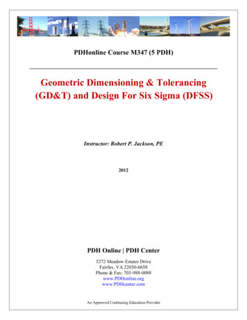
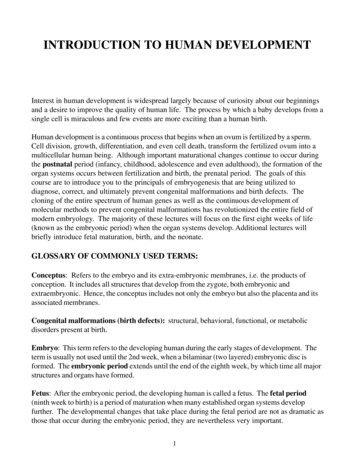
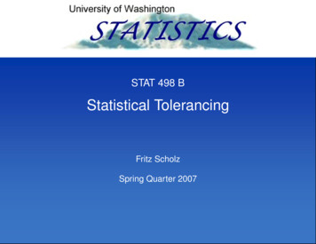
Rule #1 in Pictures Perfect form is required at MMC Variation in form is permitted as thefeature departs from MMC Maximum allowable variation inform occurs at LMC not to exceedthe boundary set by MMC
My Part Fits!Thanks GD&TThe pin can still be lobed, however now thevariation in form cannot exceed the boundary ofperfect form established at MMC
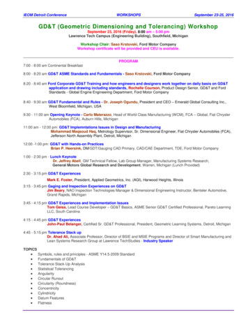
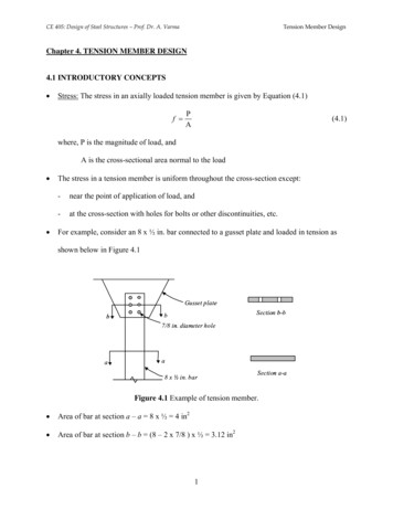
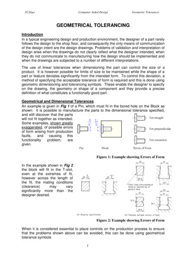
Cylindrical Tolerance ZonesRegardless of Feature Size (RFS) In the example shown, the tolerance zone diameterremains constant regardless of the hole size Datums A, B, and C establish which part features andin what order they are used to locate the tolerancezone The basic dimensions provide the exact geometricposition of the tolerance zone
Just the Tip of the Iceberg Tolerance zones can vary based on feature sizeAble to apply different constraints to location,orientation, and form all for the same featureCan add tolerance to complex surfacesTolerance zones can be projectedInterrelationship of patterned features can becontrolled separately from the pattern locationStrong application to optical assemblies due toaxis controls
Questions?
ASME Y14.5.1M-1994 . Mathematical Definition of Dimensioning and Tolerancing Principles ISO 286-1:1988 . ISO system of limits and fits — Part 1: Bases of tolerances, deviations and fits ISO 286-2:1988 . ISO system of limits and fits — Part 2: Tables of standard tolerance grades and limit deviations for holes and shafts ISO 1101:2005 . Geometrical Product Specifications (GPS .