Transcription
ASME Y14.5M-1994ASME Y14.5-2009Welcome!Changes to the ASMEDimensioning and TolerancingStandard,A SummaryBy:Jordan PepinASME GD&T Professional - Technologist & Senior Level
ASME Y14.5M-1994ASME Y14.5-2009
The Highlights Structural Changes (Formatting) New Symbology Terminology/Definition Changes Non-Uniform Zone Profile Custom Datum Reference Frames
Structural Changes19942009Section 1 – Scope and DefinitionsSection 1 – Scope and DefinitionsSection 2 – General TolerancingSection 2 – General TolerancingSection 3 – SymbologySection 3 – SymbologySection 4 – Datum ReferencingSection 4 – Datum Reference FramesSection 5 – Tolerances of LocationSection 5 – Tolerances of FormSection 6 – Tolerances of Form,Profile, Orientation, & RunoutSection 6 – Tolerances of OrientationSection 7 – Tolerances of LocationSection 8 – Tolerances of ProfileSection 9 – Tolerances of Runout
New SymbologyMovable Datum TargetAll OverUnequally Disposed ProfileTranslation ModifierIndependencyContinuous Feature
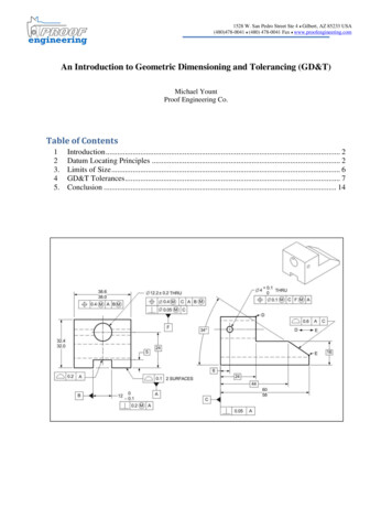
New SymbologyMovable Datum Target[g].010]A]B]C]B1C1Datum Target aremovable - movingnormal to surfaceunless other directionis statedB2C2
New SymbologyAll Over1994[g] 0.1 ]ALL OVER2009[g] 0.1 ]
New SymbologyUnequally Disposed ProfileTotal Profile Tolerance[g] XXXnXXX]A]B]C]Amount of tolerance in the “plusmaterial” direction
New SymbologyUnequally Disposed Profile1994[g] 0.1 ]A]“Alternate Practice”in the 2009 standard2009[g] 0.1 n 0.1]A]
New SymbologyTranslation Modifier
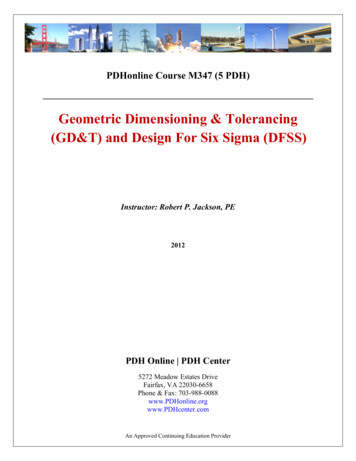
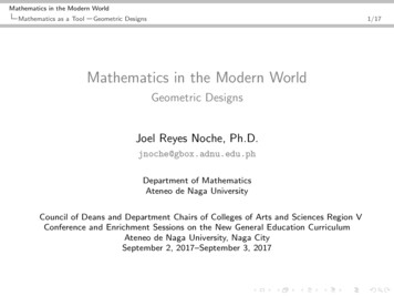
New SymbologyIndependency;.375 .010Size tolerance also controls form(the feature cannot violate theperfect form boundary at MMC);.385Perfect form boundary@MMC;.365;.365
New SymbologyIndependency;.375 .010Size tolerance also controls form(the feature cannot violate theperfect form boundary at MMC);.385Perfect form boundary@MMC65;.3;.365
New SymbologyContinuous FeatureMMC Boundaries
New SymbologyContinuous FeatureMMC Boundary*The Continuous Feature symbol can only be used for a feature of size.
Terminology/Definition ChangesModifiers;25 0 05[ä]:?).!%é]A]Bé]
Terminology/Definition Changes1994Modifiers - Ò1)Ô 2009Modifiers - ÒÔ Ò Regardless of Feature Size (RFS)1) Ò Regardless of Feature Size (RFS)- Applicable to positioned features ordatum features- Applicable to positioned features- Specifies how datum is simulated(expanding TGC)- Default condition (Ò symbol notrequired)Ò“Regardless of Material Boundary” (RMB)- When used on a datum feature- Specifies how datum is to be simulated(expanding TGC)- RFS, RMB are default condition- symbol “Ò” has been removed
Terminology/Definition Changes1994Modifiers - Ò2)Ô Ô Maximum Material Condition (MMC)2009Modifiers - Ò2) Ô Maximum Material Condition (MMC)- Applicable to toleranced features ordatum features- Applicable to positioned featuresÔ“Maximum Material Boundary” (MMB)- Specifies how datum is to be simulated(@ it’s virtual condition)3) Least Material Condition (LMC)- Applicable to toleranced features ordatum features- Specifies how datum is to be simulated(@ it’s virtual condition)Ô - When used on a datum feature- Specifies how datum is to be simulated(@ it’s MMB, not virtual condition)3) Least Material Condition (LMC)- Applicable to positioned features “Least Material Boundary” (LMB)- When used on a datum feature- Specifies how datum is to be simulated(@ it’s LMB, not virtual condition)
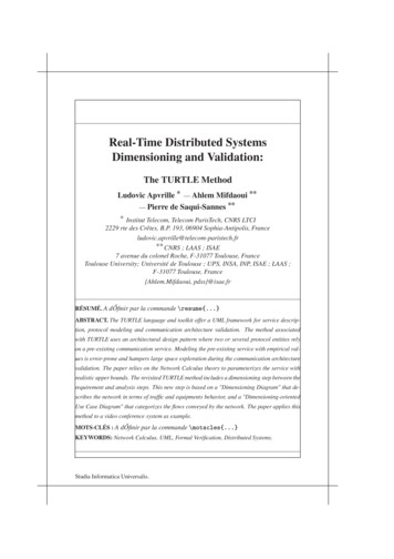
Terminology/Definition Changes2009 Modifier ExampleMMC (Maximum Material Condition)-Potential bonus positional tolerance;25 0 05[ä]:?).!%é]A]Bé]MMB (Maximum Material Boundary)-Specifies how datum is simulated
Terminology/Definition Changes1994Resultant Condition1) A variable boundaryActual Mating Envelope1) One term for a number of differentpossible boundaries depending on how itis used.2009Resultant Condition1) The single worst-case boundary (theopposite of the virtual condition boundary)Actual Mating Envelope1) Clarified by giving more specific AMEterms for the different boundaries- Unrelated AME- Related AME (oriented and/or located)- Actual Minimum Material Envelope- Related Actual Minimum MaterialEnvelope
Non-Uniform Zone Profile[g]NON-UNIFORM]abab
Custom Datum Reference FramesDatums and Degrees of Freedom
Custom Datum Reference Frames[g].004]A]B]
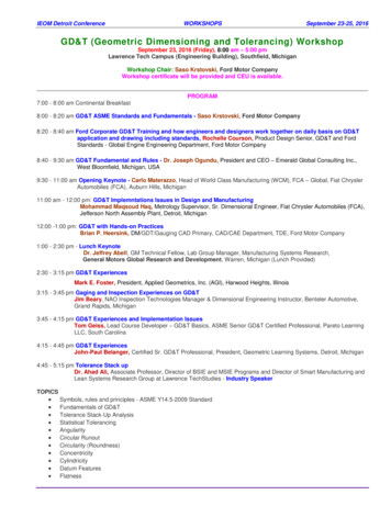
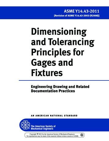
Custom Datum Reference FramesDatum A is specified to constrain only 4degrees of freedomY[g].004]A[x,y,u,v]]B[z] ]Datum B controls the 5th degreeof freedom (translation in Z)Z
Looking ForwardTwo critical components for successful implementation ofthe current standard for dimensioning and tolerancing -TrainingToolsThe GD&T standard is another “language”It’s one thing to put it on a print We will not learn it correctly withoutadequate trainingWe must have software that is able tocorrectly evaluate complex GD&TEveryone must be on the same pageMeasurement challenges-Design, Manufacturing, Quality-Datums (MMB, LMB, simultaneity)-Position (AME, simultaneity)-Profile (optimal fitting, simultaneity)-Custom Datum Reference Frames-Non-Uniform Zone ProfilesNeeds to happen from the top-down-Management must head the effort
Thank You For Coming!TrainingToolsBasic Blueprint ReadingHand Tools / GagingGD&T - Introduction & FundamentalsSurface Finish / Form AnalysisGD&T - Advanced ApplicationContact / Vision CMM’sInspection SoftwareContract Inspection Services (AIS)PQI - www.gagesite.comAIS - www.advancedinspect.comTraining - eseminar.pqi.net
Y Z. Looking Forward Two critical components for successful implementation of the current standard for dimensioning and tolerancing - Training The GD&T standard is another “language” We will not learn it correctly without adequate training Everyone must be on the same page-Design, Manufacturing, Quality Needs to happen from the top-down-Management must head the effort Tools It’s one .