Transcription
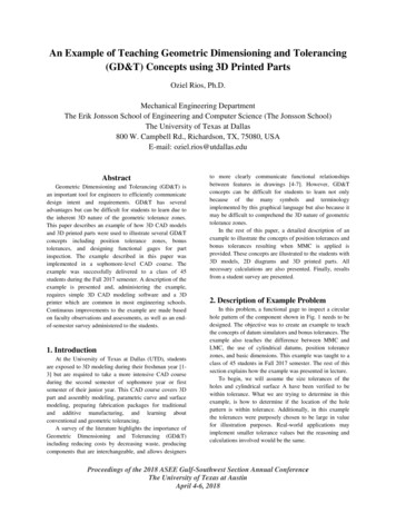
An Example of Teaching Geometric Dimensioning and Tolerancing(GD&T) Concepts using 3D Printed PartsOziel Rios, Ph.D.Mechanical Engineering DepartmentThe Erik Jonsson School of Engineering and Computer Science (The Jonsson School)The University of Texas at Dallas800 W. Campbell Rd., Richardson, TX, 75080, USAE-mail: oziel.rios@utdallas.eduAbstractGeometric Dimensioning and Tolerancing (GD&T) isan important tool for engineers to efficiently communicatedesign intent and requirements. GD&T has severaladvantages but can be difficult for students to learn due tothe inherent 3D nature of the geometric tolerance zones.This paper describes an example of how 3D CAD modelsand 3D printed parts were used to illustrate several GD&Tconcepts including position tolerance zones, bonustolerances, and designing functional gages for partinspection. The example described in this paper wasimplemented in a sophomore-level CAD course. Theexample was successfully delivered to a class of 45students during the Fall 2017 semester. A description of theexample is presented and, administering the example,requires simple 3D CAD modeling software and a 3Dprinter which are common in most engineering schools.Continuous improvements to the example are made basedon faculty observations and assessments, as well as an endof-semester survey administered to the students.1. IntroductionAt the University of Texas at Dallas (UTD), studentsare exposed to 3D modeling during their freshman year [13] but are required to take a more intensive CAD courseduring the second semester of sophomore year or firstsemester of their junior year. This CAD course covers 3Dpart and assembly modeling, parametric curve and surfacemodeling, preparing fabrication packages for traditionaland additive manufacturing, and learning aboutconventional and geometric tolerancing.A survey of the literature highlights the importance ofGeometric Dimensioning and Tolerancing (GD&T)including reducing costs by decreasing waste, producingcomponents that are interchangeable, and allows designersto more clearly communicate functional relationshipsbetween features in drawings [4-7]. However, GD&Tconcepts can be difficult for students to learn not onlybecause of the many symbols and terminologyimplemented by this graphical language but also because itmay be difficult to comprehend the 3D nature of geometrictolerance zones.In the rest of this paper, a detailed description of anexample to illustrate the concepts of position tolerances andbonus tolerances resulting when MMC is applied isprovided. These concepts are illustrated to the students with3D models, 2D diagrams and 3D printed parts. Allnecessary calculations are also presented. Finally, resultsfrom a student survey are presented.2. Description of Example ProblemIn this problem, a functional gage to inspect a circularhole pattern of the component shown in Fig. 1 needs to bedesigned. The objective was to create an example to teachthe concepts of datum simulators and bonus tolerances. Theexample also teaches the difference between MMC andLMC, the use of cylindrical datums, position tolerancezones, and basic dimensions. This example was taught to aclass of 45 students in Fall 2017 semester. The rest of thissection explains how the example was presented in lecture.To begin, we will assume the size tolerances of theholes and cylindrical surface A have been verified to bewithin tolerance. What we are trying to determine in thisexample, is how to determine if the location of the holepattern is within tolerance. Additionally, in this examplethe tolerances were purposely chosen to be large in valuefor illustration purposes. Real-world applications mayimplement smaller tolerance values but the reasoning andcalculations involved would be the same.Proceedings of the 2018 ASEE Gulf-Southwest Section Annual ConferenceThe University of Texas at AustinApril 4-6, 2018
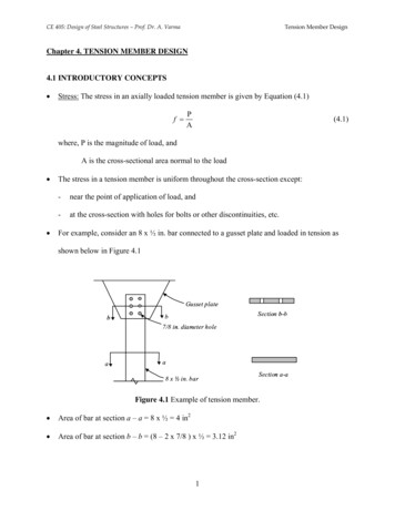
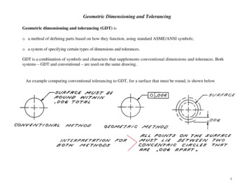
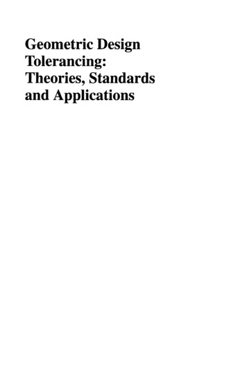
locations are given by the basic dimensions specified in thedrawing of Fig. 1. This functional gauge is designed at thelowest end of the tolerance that would allow parts shown inFig. 1 to still be accepted.The first step involves determining the diameters of thepins. Looking at the feature control frame, the position ofthe holes are toleranced relative to the MMC size of thehole and the MMC size of the cylindrical datum A. TheMMC of the hole (internal feature of size) is 𝜙0.45 𝑖𝑛 andthe MMC of datum A (external feature of size) is 𝜙1.55 𝑖𝑛.Next, referencing the diagram of Fig. 2, the pin diameter ofthe functional gage, 𝐷𝑝 , is determined to be𝐷𝑝 𝐷ℎ,𝑀𝑀𝐶 𝑑𝑡𝑜𝑙 𝜙0.45 𝑖𝑛 𝜙0.10 𝑖𝑛 𝜙0.35 𝑖𝑛(1)In Eq. 1, 𝐷ℎ,𝑀𝑀𝐶 and 𝑑𝑡𝑜𝑙 are the diameters of the hole sizeat MMC and position tolerance zone specified in thefeature control frame, respectively.Fig. 1, The component with a circular hole patterndimensioned in units of inches. Dimensions and tolerancesof some features are not shown for clarity.Fig. 4, Diagram used to determine position tolerance forcase (I).Fig. 2, Diagram used to determine functional gage pindiameter.Gage pins atbasic locationsDatum ADatum BFig. 3, The functional gage designed for this applicationwith simulated datums A (cylindrical) and B (planar).The hole positions can be verified to be withintolerance using a functional gage with five pins whoseFig. 5, Diagram used to determine position tolerance forcase (II).Since MMC was implemented in the component of Fig.1, a functional gage can be designed to verify the positionsof the holes. The functional gage designed for thisapplication is shown in Fig. 3. For simplicity in thisundergraduate class, we assumed the variation of thesimulated datums A and B was much less compared to theProceedings of the 2018 ASEE Gulf-Southwest Section Annual ConferenceThe University of Texas at AustinApril 4-6, 2018
variation of the surfaces of the component making contactwith the simulated datums of the functional gage.Next, we wanted to show what happens to the positiontolerance zone if the hole and datum A were manufacturedat their respective LMC values instead of their MMCvalues. This was addressed incrementally in two cases:I) Hole at LMC and datum A at MMCII) Hole and datum A at LMCHence, when the hole size and cylindrical surface A deviatefrom their MMC values, the allowable variation of the holesize is up to 3 times the position tolerance specified by thedesigner in the feature control frame.Since MMC condition is typically implemented indrawings when components are to be fabricated usingconventional subtractive manufacturing techniques/tools toreduce scrap, the bonus tolerance should be determined andthe functional requirements of the component should beassessed with this additional allowance in variation.The scenario of case (I) is detailed in Fig. 4. In this(I)3. 3D Printed Partscase, the allowable variation of hole position, 𝑑𝑡𝑜𝑙 , is(I)𝑑𝑡𝑜𝑙 𝐷ℎ,𝐿𝑀𝐶 𝐷𝑝 𝜙0.55 𝑖𝑛 𝜙0.35 𝑖𝑛 𝜙0.20𝑖𝑛(2)where 𝐷ℎ,𝐿𝑀𝐶 is the diameter of the hole at LMC. Hence,(I)the bonus tolerance for case (I), 𝑑𝑏𝑜𝑛𝑢𝑠 , is(I)(I)𝑑𝑏𝑜𝑛𝑢𝑠 𝑑𝑡𝑜𝑙 𝑑𝑡𝑜𝑙 𝜙0.20 𝑖𝑛 𝜙0.10 𝑖𝑛 𝜙0.10 𝑖𝑛(3)Since the position tolerance zone is defined relative to thehole's MMC size, when the hole size deviates from it'sMMC value a bonus tolerance results up to 𝜙0.10 𝑖𝑛.The scenario of case (II) is detailed in Fig. 5. In thiscase, the additional variation of the cylindrical surface A,𝑑𝐴,𝑣𝑎𝑟 , needs to be taken into account. This is determinedas follows:𝑑𝐴,𝑣𝑎𝑟 𝑑𝐴,𝑀𝑀𝐶 𝑑𝐴,𝐿𝑀𝐶 𝜙1.55 𝑖𝑛 𝜙1.45 𝑖𝑛 𝜙0.10 𝑖𝑛(4)where 𝑑𝐴,𝑀𝑀𝐶 and 𝑑𝐴,𝐿𝑀𝐶 are the MMC and LMC values ofdatum A, respectively. The allowable variation of the holeposition is now(II)𝑑𝑡𝑜𝑙 𝐷ℎ,𝐿𝑀𝐶 𝑑𝐴,𝑣𝑎𝑟 𝐷𝑝 𝜙0.55 𝑖𝑛 𝜙0.10 𝑖𝑛 𝜙0.35 𝑖𝑛 𝜙0.30𝑖𝑛(5)This yields a bonus tolerance of(II)(II)𝑑𝑏𝑜𝑛𝑢𝑠 𝑑𝑡𝑜𝑙 𝑑𝑡𝑜𝑙 𝜙0.30 𝑖𝑛 𝜙0.10 𝑖𝑛 𝜙0.20 𝑖𝑛(6)For some students, the 3D models of component andfunctional gage and the diagrams shown in Fig. 2, Fig. 4and Fig. 5 may not be sufficient to understand the conceptsof datum simulators, position tolerance zones, and bonustolerances due to the inherent 3D nature of these concepts.To help with this, a 3D printed functional gage and two 3Dprinted components were developed and passed out to thestudents during lecture. One 3D printed component wasdesigned so that the hole pattern would pass inspectionwhile the second component was designed so that it wouldnot. Both 3D printed components were designed with allfeatures within tolerance except, in the second component,the location of one hole was purposely selected to beslightly beyond the boundary specified by the allowablevariation calculations (Eq. 2 and Eq. 5). To the author'seye, there was no visual difference between the two 3Dprinted components. The students used the functional gageto inspect the hole pattern implementing the datum priorityset in the feature control frame.The 3D printed functional gage and components werefabricated using a Dimension Elite 3D printer with a layerthickness of 0.007 𝑖𝑛. This 3D printer implements FusedDeposition Modeling (FDM) with support material removal[8]. Since the sizes and tolerances implemented were largecompared to the layer thickness, the components andfunctional gage performed as intended.4. Results of a Student SurveyStudents were asked to provide anonymous feedback onthe activity in a survey administered at the end of thecourse. The survey includes the student's perception of theirunderstanding of the example topics and if the 3D printedcomponents and functional gage helped them understandsome of these topics. The students were asked to respond tothe following statements based on a 5-point Likert scalewhere a value of 1 meant they strongly disagreed and avalue of 5 meant that they strongly agreed with thestatement.1) I understand why the geometric tolerancescontrolling position require the use of datums.Proceedings of the 2018 ASEE Gulf-Southwest Section Annual ConferenceThe University of Texas at AustinApril 4-6, 2018
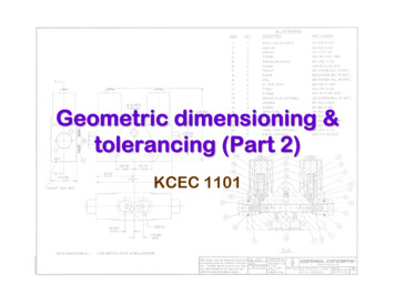
2) I understand why a bonus tolerance can result whenposition geometric tolerances and MMC areapplied.3) I understand why a functional gage can be used tocheck position geometric tolerances at MMC.4) The 3D printed components and functional gageshown in class helped me understand the concept ofbonus tolerance.5) The 3D printed components and functional gageshown in class helped me understand how afunctional gage can be used for part inspection.The results of these are plotted in a diverging staked barchart [9] as shown in Fig. 6. The raw data is given in Table1. Out of 45 students in the class, 28 students responded tothe survey and allowed their anonymous responses be usedfor research purposes."all the symbols and their meanings." Some studentsexplained they benefited from the examples: "I think it washard visualizing this but the examples helped," and "lectureslides and examples were helpful."After reviewing the student's comments and positivefeedback on the example with 3D printed parts, introducingmore examples like this would be greatly beneficial. Tothis end, one or more examples with detailed calculations,diagrams, 3D models, and 3D printed parts will be createdfor future semesters.5. SummaryIn this paper, an example to illustrate GD&T conceptsusing 3D models and 3D printed parts was described. Theexample is considered simple to implement only requiringCAD software and a 3D printer and was successfullyadministered to 45 students. Results from a student survey(28 respondents) indicate the example had a positive effecton the student's understanding of the concepts.AcknowledgementThe author would like to thank Dr. Dani Fadda for hissupport of this work.ReferencesFig. 6, Student responses to survey questions.Table 1, Number of students who strongly disagree (SD),disagree (D), agree (A), strongly agree (SA) and whereneutral (N) with the 323711528411910728512512828As can be seen from Fig. 6, over 57% of the studentswho responded to the survey either agreed (A) or stronglyagreed (SA) with each of the statements. Homeworkassignments and exam questions also indicatedunderstanding of the concepts.Students were also asked to provide free-responsecomments on the difficulties they faced learning aboutgeometric tolerances. Some students could have benefitedfrom more lectures (only an introduction is intended in thiscourse): "need more practice," and "not solving enoughproblems." Some students had difficulty understanding thetolerance zones: "the shape of tolerance zone," and"location tolerances." A student mentioned difficulty with[1] Rios, O. and Fadda, D., "A Mechanical EngineeringActivity-Based Freshman Course," Proceedings of theASME IMECE, Nov. 3-9, Tampa, Florida (2017)[2] Rios, O. and Fadda, D., "A First-Year Design-BasedActivity for Mechanical Engineering Students,"Proceedings of the ASEE Gulf-Southwest Section AnnualConference, University of Texas at Dallas, Richardson,Texas (2017)[3] Fadda, D. and Rios, O., "Designing a Scalable StaticsProject for a First-Year Mechanical Engineering Course,"First Year Engineering Experience (FYEE) Conference,August 6-8, Daytona Beach, Florida (2017)[4] Lin, C. and Verma, A., "Clarifications of Rule 2 inTeaching Geometric Dimensioning and Tolerancing,"Proceedings of the ASEE Annual Conference andExposition, June 24-27, Honolulu, Hawaii (2007)[5] Waldorf, D. J. and Georgeou, T. M., "GeometricDimensioning and Tolerancing (GD&T) IntegrationThroughout a Manufacturing Engineering Curriculum,"Proceedings of the ASEE Annual Conference andExposition, June 26-29, New Orleans, Louisiana (2016)[6] Paige, M. A. and Fu, K., "Spatial Demonstration Toolsfor Teaching Geometric Dimensioning and Tolerancing(GD&T) to First-Year Undergraduate EngineeringStudents," Proceedings of the ASEE Annual Conferenceand Exposition, June 25-28, Columbus, Ohio (2017)Proceedings of the 2018 ASEE Gulf-Southwest Section Annual ConferenceThe University of Texas at AustinApril 4-6, 2018
[7] Sriraman, V. and De Leon, J., "Teaching GeometricDimensioning and Tolerancing in a ManufacturingProgram," Journal of Industrial Technology, Vol. 15, No. 3(1999)[8] www.stratasys.com, "Dimension Elite User Guide,"Document #204400-0002 (2007)[9] Robbins, N. B. and Heiberger, R. M., "Plotting Likertand Other Rating Scales," Joint Statistical Meeting, Sectionon Survey Research Methods (2011)Proceedings of the 2018 ASEE Gulf-Southwest Section Annual ConferenceThe University of Texas at AustinApril 4-6, 2018
Geometric Dimensioning and Tolerancing (GD&T) is an important tool for engineers to efficiently communicate design intent and requirements. GD&T has several advantages but can be difficult for students to learn due to the inherent 3D nature of the geometric tolerance zones.