Transcription
DFMA Design for Assembly Manufacturingby Bob WarfieldWhat is DFMA (Design for Manufacturing andAssembly)?DFMA stands for “Design for Manufacture and Assembly” also “Design forManufacturing and Assembly.”It consists of two sub-methologies: DFA: Design for AssemblyDFM: Design for ManufacturingIt’s purpose is to reduce costs by making changes during the design phase. As such, itis considered part of Lean Manufacturing.DFMA is also a registered trademark of Boothroyd Dewhurst, who use it as the nameof their integrated set of software products.During the 1970’s, University of Massachusetts Professor Geoffrey Boothroyd andcolleagues did research that would eventually lead to DFMA. One of their importantfindings was that the then-prevalent wisdom of minimizing the complex of individualparts to reduce the cost to manufacture was often not the best approach.In 1980, Dr peter Dewhurst joined Dr Boothroyd to create the first commercial DFMAsoftware package, which ran on Apple II’s.DFMA Basics VideoHere’s a video from my monthly CNC Chef series for Cutting Tool Engineering:Design for Manufacturing and Assembly from Cutting Tool Engineering on Vimeo.
Critical Insight: Save Costs at Design TimeThe biggest insight of the DFMA process is that most of the available cost savings areat Design Time. It’s not hard to understand why–making changes to CAD drawings is alot cheaper than changing a manufacturing assembly line that’s all tooled up. That’sprobably an over simplification of all that’s involved, but you get the idea.
The Design Office to Shop Floor CommunicationLoopIn the early days of manufacturing, the designers were in close proximity to the ShopFloor where parts were being manufactured. They heard about problems inmanufacturing quickly and could easily visit the Shop Floor to see things firsthand. Assuch, a formal process and methodology were not as important.As modern supply chains evolved, that communication loop between the Design Officeand Shop Floor became increasingly strained. Job Shops moved the shop floor toanother company entirely that was across town in the best case and across the countryin the worst. Offshoring moved the Shop Floor even further away and added languageand cultural barriers as well.Faced with those challenges, communication between the Design Office and ShopFloor broke down. A formal process was needed, and that process is DFMA.
DFMA Can Help Job Shops Add ValueWhile traditional DFMA is intended to be practiced at the Design Office, it need not bedone exclusively there. Job Shops and Shop Floor personnel may have DFMA insightstoo. In fact, telling prospective customers ideas to reduce manufacturing costs duringthe bidding process is an ideal way for Job Shops to add value and impress prospectivecustomers.Who wouldn’t want a Job Shop to provide valuable insight into how to reducemanufacturing costs?DFMA (Design for Manufacturing and Assembly)ExamplesLet’s start with a process. DFMA is typically done DFA first and then DFM second. It’sdone in this order because one of the main tenets of DFA (Design for Assembly) is toreduce the number of parts as much as possible. There’s no sense optimizing themanufacture of parts we eliminate during DFA!Let’s drill down and see some DFA and DFM Examples.
Design for Assembly ExamplesDFA (Design for Assembly) is all about reducing the number of parts that must bemanufactured and reducing the cost to assemble the parts into a finished product.To reduce the number of parts, try to combine parts. Two parts can be combined if theymeet the following conditions: They don’t move relative to one another.They can be made of the same material and still meet the part’s functional requirements.Once you’ve successfully minimized the number of parts in a design, it’s time to make itcheaper and easier to assemble the parts.An important principle is to design symmetrical parts that will fit regardless oforientation. That way the assembler can’t make a mistake with the wrong orientationand doesn’t even have to think about orientation. Symmetry is just one subset ofthe Lean Manufacturing Poka-Yoke concept, which is aimed at mistake proofing.Another tenet of Design for Assembly / DFA is to reduce fasteners and use lessexpensive fasteners. On average, fasteners are 5% of overall part cost but can be asmuch as 70% of the cost to assemble a part!
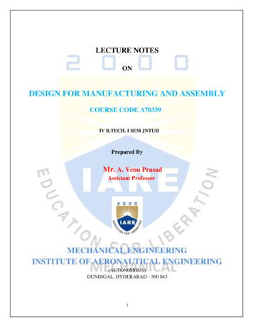
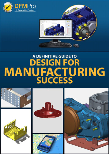
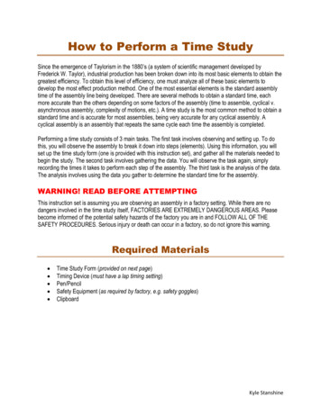
Here’s an example of preferred fastening methods to reduce costs:Here’s a good example of the “before” and “after” of a DFA process for a part:Notice how many fewer components are on the right.A good benchmark is that a typical DFA process can reduce manufacturing costs by25%.
Design for Manufacturing ExamplesHaving minimized the number of parts needed through DFA as well as makingassembly easier and cheaper, it’s time to look at the cost to manufacture each individualpart. That’s the role of DFM or Design for Manufacturing.There are basically 4 steps needed in DFM:1. Pick the best process. Should your part be cast, sheet metal fabbed, CNC Machined,or?2. Pick the best material. What’s the cheapest material in all respects (easy to work within the chosen process is a factor) for the part?3. Tolerances: What are the absolute minimum number of Tolerances with the widestallowable variance that will allow the part to function properly?4. Optimize the Process: Investigate changes to particular aspects of geometry and partfeatures to reduce costs.Pretty straightforward, but there’s a fair bit of work to getting DFM right because it is socomprehensive.I will leave the choice of process and material for other articles, but I do want to talkabout those last 2 steps.
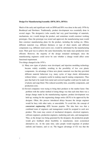
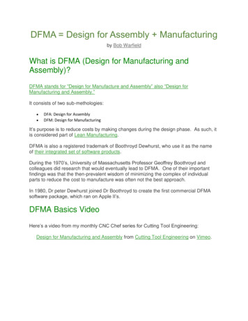
The High Cost of TolerancesMost designers are shocked when they learn how expensive too tight tolerances canbe. Here’s a simple chart that makes the point:It’s taken from our more comprehensive article, The High Cost of Tolerances, but youget the idea. I have two takeaways for you about Tolerances:1. Don’t over tolerance parts!2. Use GD&T instead of simple /- tolerancing.GD&T (Geometric Dimensioning and Tolerancing) is a more modern way of expressingtolerances than simple /- tolerancing. It can allow you to keep tolerances tight enoughfor part function while providing wiggle room that won’t matter to function but savescost.
I highly recommend our free GD&T Training if you’re not familiar with it:[ Check out the Free CNCCookbook GD&T Coursetoday! ]Design for Manufacturing Principles and GuidelinesSo, you’ve got Process, Materials, and Tolerances under control. It’s time to take thefinal step by optimizing the part’s geometry and certain features to minimizemanufacturing costs further. Here’s our giant list of DFM Principles and Guidelines tohelp:Material ShapeMaterial SizeRough StockPreparationKeepTolerancesLooseConsider which shapes are cheaper to acquire versus which shapes are closerto the finished part and hence require less machining to complete. Bar stockcan often be had for 1/2 the cost of plate for a given material, but you canwaterjet more parts out of a plate. It’ll take some careful calculations to tellwhich is cheaper to manufacture. If volumes are large enough castings orextrusions may further reduce machining time.When deciding your part’s dimensions, visualize how they will interact with therough stock sizes that are available. You need an allowance for machining thatdoesn’t require too much step up in rough stock size lest you waste the timeand material cost of turning that extra stock into chips.The cheapest form of material removal often comes at the rough stockpreparation stage. For example, if you can start machining operations on awaterjet cut blank, you may only need one pass instead of a bunch of roughingpasses followed by a finish pass.The tighter the tolerances, the higher the manufacturing costs. Don’t specifytight tolerances unless they’re really needed. One of the most expensivetolerances is thread depth, and it often doesn’t matter. Specifying thread depthto three decimal places is seldom going to accomplish much other than drivingup costs substantially. More on the cost of tight tolerances.
Depth of Cut vsRadius ofCornersThrough Holesand DeepHolesEdgePreparationAvoid MirrorImage PartsAvoid ThinWalls, ThinWebs, andSimilarFeaturesAvoidUndercuts andSimilarFeatures thatYou can’t cut a tight corner radius with a tool whose diameter is more than twicethe corner radius. At the same time, the stiffness of a tool changes with the thirdpower of length and the fourth power of diameter. Making the tool twice as longmakes it 1/8 as rigid. Making the tool twice the diameter makes it 16x morerigid. Therefore, avoid designing parts with tight radius corners that are verydeep.A good guideline is keep the ratio to 3:1 depth vs diameter (2x corner radius).So, a pocket with a 1/4″ corner radius should be no more than 1.5″ deep oryou’ll greatly increase the manufacturing costs.Here’s another tip: choose a corner radius just slightly larger than the endmillradius that will be used to make the corner. This reduces the loads on theendmill due to lower tool engagement angles in the corner and will reduce yourmanufacturing costs as a result either by allowing the endmill to be fed faster orby causing it to last longer.Where possible, specify through holes as they facilitate chip evacuation. This isparticularly important on holes that will be reamed or threaded.Deep holes are also much more expensive to manufacture. Try to keep the ratioof length to diameter under 4 (no holes more than 4 diameters deep) for bestresults. Any hole over 10 diameters deep is likely to be problematic, there aretools like G-Wizard’s Deep Hole Wizard to help.It’s generally cheaper to chamfer an edge than to radius the edge.Mirror image parts are generally used in pairs in an assembly. If the assemblycan be designed so that both parts can be identical, great savings can be hadbecause you’ll be producing twice the volume of half the part types.Thin walls and webs are prone to chatter (which slows down machiningspeeds), distortion (so it’s hard to hold tolerances with them), and are moreeasily damaged on the assembly line.Undercuts are a lot more trouble to program and machine in most cases somake sure you really need them before specifying them on a part. Undercutscan be eliminated in surprising ways if you can learn to Think Like a PlasticsEngineer.
RequireSpecialMachiningProvide ToolClearanceWhen TurningThreads andTappingUse BossesInstead ofLarge FlatAreasMake FloorRadius Smallerthan CornerRadius inPocketsMinimizeSetups90 degree shoulders provide less tool clearance than tapered shoulders and soare more trouble. Also, if you’re turning down an area to achieve a tolerance, ifthe shoulders bordering the area are perpendicular a burr is more likely to beformed than if they’re not.There are a myriad of ways to minimize the costs associated with threads andtapping including:– Minimize the threaded length in the hole. 1.5x the major diameter oftenprovides sufficient strength.– Avoid blind holes where possible. If you must thread a blind hole, allow roomat the bottom of the hole for 1/2 major diameter more than the threads.– Don’t over-specify the thread percentage. A 75% thread has 95% of thestrength of a 100% thread but only requires 1/3 the torque–so it is much lesslikely to break a tap. G-Wizard Calculator can help you select the right twist drillfor particular thread percentages.– Avoid tight tolerances on thread depths as they’re expensive to implement.– ProCNC has a number of good DFM guidelines for threads and threading.Where precision mounting is desired, consider using bosses around the dowelpins or fasteners rather than specifying the entire area be flat. It’s cheaper tomake the bosses flat and the flat area may not be adding any value to the part.It’s easy to turn out a CAD drawing where the radius on the floor to wall edge isthe same as the radius in a corner, but it’ll cost more to produce because it willlikely require a ballnose cutter to do the floor radius which means an extra passwith an extra tool. Specify a small radius for the floor that is available on abullnosed end mill that can be used to do all the machining in the pocket.Where possible design parts to be made in as few setups as possible–preferably in one setup.For turning, try to put all the precision features so they can be turned in one gowithout having to remove or “flip” the part. Especially avoid rechucking tomachine features that must be concentric with features before rechucking.
Design forMultiple Setupsand FixturingMinimizeToolingRequirementsDesign forAssembly(DFA)Select a GentleEntry to theCutIf you must use multiple setups, follow design practices that minimize the cost.When a part will require multiple setups, design the fixtures and parts so it isimpossible to put the part into the fixture incorrectly. This can mean adding keysor asymmetrical features such as the placement of holes that interact with thefixture. Making it impossible to orient the part wrong in the fixture will ensuregreater success for our operators and avoid costly mistakes on parts thatalready have prior machining operations invested in them.Even better is to make every part symmetrical so that no matter which way it isoriented in the fixture, it will be correctly machined.Provides features on the part that make alignment in the fixture easy.Be cognizant that the machine tool has a limited number of slots in its toolchanger and each one is valuable. Try to design the part to use as few differenttools as possible. For example, you may be able to use a spot drill tocountersink a flathead cap screw. You may be able to reduce the number of drillsizes needed by using interpolation and an endmill for several hole sizes. Youmay be able to reduce the number of taps needed by using thread milling. Ifyou’re working on a very expensive assembly that needs to be tapped after lotsof hours of machining, consider thread milling instead of tapping–if the threadmill breaks it won’t be stuck in the hole.Each of those ideas carries trade offs that have to be evaluated to determinewhich will truly yield a lower cost of manufacturing.Design for Assembly is a subset of Design for Manufacturing. The idea is tochange the design to make it easier to assemble the parts. There are a lot oftechniques around this, but here are two examples:– Keep the tolerances on bolt holes loose to allow for faster fit against a widerarray of potential misalignments.– Use fewer fasteners. Bolts are primarily good for holding and so-so foralignment. Machine features into the parts that ensure alignment withoutrequiring the bolts to do so.Many CAM programs offer a wide variety of entry methods: plunge, ramp, helixdown, etc. Some of these methods are far gentler than others. Be familiar withthe best methods and select these over the harsher approaches. For moreinformation see our “Toolpath Considerations” chapter from the Feeds andSpeeds Cookbook.
Give Bolts aLoose FitKeep as much clearance as possible in the holes that locate bolts. This providesa margin for error if things don’t line up quite right. Clearance may be achievedwith oversized holes, or even by having slots rather than holes. Remember: youcan’t move threaded holes! If things don’t line up, your best bet is moreclearance in the non-threaded holes.Avoid FlatBottom HolesBlind holes must be cut with a drilling tool that has a conical bottom. To finish aflat bottom may require an extra operation or may make the overall operationslower.Avoid PartialHolesPartial holes are those where the drill axis is less than a hole radius from theedge of the material. They’re hard to machine accurately as the tip wants towander.Keep the holeaxisperpendicularto the surfaceDrilling into an angled surface is prone to tip wander. To avoid it requires millinga shallow pocket before drilling which makes the hole more expensive tomachine.Avoid Deep,Narrow SlotsKeep the final depth of cut less than 15x end milldiameter for soft materials(wood or plastic), 10x diameter for aluminum, and 5x diameter steel. Longertools are prone to deflection and vibration which leads to bad surface finish,poor tool life, and poor tolerances.Design with theLargestPossibleInternall RadiiThe smaller the internal radius, the smaller the end mill that may be used,making the job more expensive. Ideally, make the radius slightly larger than astandard endmill size too.Avoid LongThin PartsWhen TurningThey may require a tailstock or other means of support.Keep straightparallel outsideedgesThis makes workholding easier when outside edges are straight and parallel.Keep straightinside edgesIf the walls of a pocket are not vertical, they will be more expensive to machine.
Minimize ToolChangesAny change that saves a tool change will save time. For example, using fewerunique hole sizes.Inside Filletsvs ChamfersInside chamfers are time consuming and difficult to create. Inside fillets areeasier to make because round tipped endmills can be used.Avoid smoothround edgesPutting a radius on all the edges may make a part look better, but it also makesit more expensive to machine. Simply specify “break all edges” and let the shopfind the most cost-effective way to do that. If a more extensive treatment isneeded, chamfering is preferable to rounding. If you must radius the edges, atleast make them all the same radius so multiple tools aren’t needed.Use GD&TRather Than /TolerancesGD&T tolerancing can be more lenient than /- tolerancing in many cases.
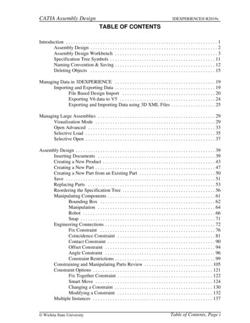
Resources: How to Implement DFMA / DFM / DFA inYour ShopThe best place to inject these methods into a shop is at the interface with the DesignOffice. If you’re a Job Shop, that’s probably during the process of quoting the job. Ifyou design and then manufacture your own parts, implement DFMA as part of theDesign Process.Whomever will be responsible for DFMA needs a good education in the practice. Thereare lots of online articles and handbooks out there to choose from.DFM & DFMA SoftwareThere are software packages available to help you–DFM Software, DFA Software, andDFMA Software are all available.Our own G-Wizard Estimator (for job quoting and cost estimation) and G-WizardCalculator offer DFM advice built right in:DFM Tips like this one for pocket depth are built right into G-Wizard If you haven’t tried it, go ahead, we offer a free 30-day trial.
2. Use GD&T instead of simple /- tolerancing. GD&T (Geometric Dimensioning and Tolerancing) is a more modern way of expressing tolerances than simple /- tolerancing. It can allow you to keep tolerances tight enough for part function while providing