Transcription
Geometric dimensioning &tolerancing (Part 2)KCEC 1101
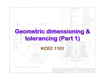
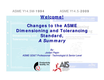
Tolerances Geometric tolerances are controls that effect theshape and/or orientation of features. Tolerance is the total amount a dimension may varyand is the difference between the maximum andminimum limits. Tolerances are assignedto mating parts. Forexample, the slot in thepart must accommodateanother part. A system istwo or more mating parts.One of the greatadvantages of usingtolerances is that it allowsfor interchangeable parts,thus permitting thereplacement of individualparts.
For example, Atolerance of 4.650 0.003 means thatupper limit (largestvalue) for part is4.653, the lower limit(smallest value) is4.647, and thetolerance is 0.006
Tolerances are expressed as:1. Direct limits, or as tolerance valuesapplied directly to a dimension2. Geometric tolerance3. Notes referring to specific conditions4. A general tolerance note in the titleblock
1. Direct limits or as tolerance valuesapplied directly to a dimension.
2. Geometric tolerances & dimensioning.
Tolerance can be unilateral or bilateral. A unilateral tolerance varies in only one direction,while a bilateral varies in both directions. If the variation is equal in both directions, then thevariation is preceded by a symbol. The plus andminus approach can only be used when the twovariations are equal.
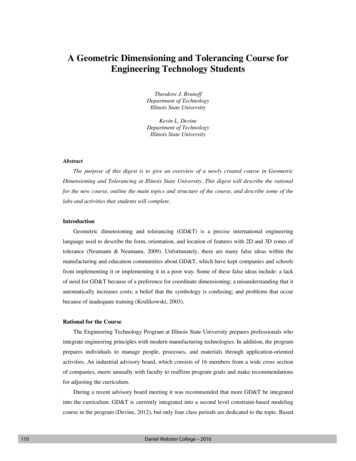
Important terms in ASME Y14.5M-1994(A system of two part with tolerance dimension)Mating partThe slot part
Nominal size - a dimension used todescribe the general size usuallyexpressed in common fractions.The slot in Fig has a nominal size½” or 0.5”
Basic size the theoretical size usedas a starting point for the applicationof tolerances.The basic size of the slot in Fig is.500”.
Actual size the measured size ofthe finished part after machining.In Fig, the actual size is .501
Limits the maximum and minimumsizes shown by the toleranceddimension.The slot has limits of .502 and .498The mating part has limits of .495and .498
Allowance is the minimum clearance ormaximum interference between parts.In Fig. the allowances is .001, meaning thatthe tightest fit occurs when the slot ismachined to its smallest allowable size of.498 and the mating part is machined to itslargest allowable of size of .497.The difference between .498 and .497 (or.001) is the allowance.
Tolerance is the total variance in adimension which is the difference betweenthe upper and lower limits.The tolerance of the slot part in Fig. is .004"and the tolerance of the mating part is .002".
Maximum material condition (MMC) is thecondition of a part when it contains the mostamount of material.The MMC of an external feature such as ashaft is the upper limit.The MMC of an internal feature such as ahole is the lower limit.
Least material condition (LMC) is thecondition of a part when it contains the leastamount of material possible.The LMC of an external feature is the lowerlimit of the part.The LMC of an internal feature is the upperlimit of the part.
Piece tolerance – the differencebetween the upper and lower limits of asingle partSystem tolerance – the sum of all thepiece tolerance
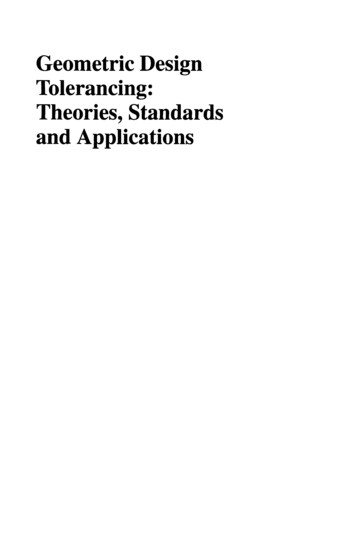
Fit types The degree of tightness between mating parts iscalled the fit. Clearance fit occurs when two toleranced matingparts will always leave a space or clearance whenassembled.The largest that shaft (A) can bemanufactured is .999 and thesmallest the hole can be is 1.000.The shaft will always be smallestthan the hole.Formula:Allowance smallest hole – largest shaft
Fit types Interference fit occurs when two toleranced matingparts will always interfere when assembled. This fit type would be necessary to stretch the holeor shrink the shaft or to use force to press the shaftinto the hole.For example this fit type canbe used to fasten two partstogether without the use ofmechanical fasteners oradhesiveFormula:Allowance smallest hole – largest shaft
Fit types Transition fit occurs when two toleranced matingparts will sometimes be an interference fit andsometimes be a clearance fit when assembled.Allowance largest hole – smallest shaftAllowance smallest hole – largest shaft
Fit typedetermination The loosest fit is thedifference betweenthe smallest feature Aand the largestfeature B. The tightest fit is thedifference betweenthe largest feature Aand the smallestfeature B.
Functionaldimensioning When dimensioning apart it is critical tostart out by identifyingthe functional featuresfirst. Many times thesefeatures are holes. Any other featuresthat come in contactwith other parts,especially movingparts, are consideredfunctional. Dimensionthese features first,then all other nonfunctional featurescan be considered.
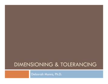
Tolerance Stack-Up The additive rule for tolerances is thattolerances taken in the same directionfrom one point of reference areadditive The corollary is that tolerances to thesame point taken from differentdirections becomes additive. The effect is called tolerance stack-up
Tolerance stack-up(cause assemblyproblem)Tolerance stack-upeliminated(used same reference)Alternate dimension(A method locatingthe pattern first)
Coordinate dimensionstack-upAvoid coordinate dimensionstack-up by using a commonpoint and dimensioning thehole spacing directly (B)
Metric limits and fits The standards used for metricmeasurements are recommended bythe ISO and are given in ANSI B4.21978 The terms used in metric tolerencingare follows:
Basic Size is the size to which limits of deviation areassigned and are the same for both parts.
Metric symbolsand theirdefinitionsH – Hole basis is the system offits where the minimum hole sizeis the basic size.f – Shaft basis is the system of fitswhere the minimum shaft size isthe basic size.
Three methods of showing metrictolerance symbols used for dimensionsThe values in parentheses are for reference only and come fromANSI Standard B4.2-1978 tables
Example Determine the Toleranceusing The Hole Basis System Given:––––A shaft & HoleThe hole basis systemClearance fit, andA basic diameter of 41mm for the hole
Example Determine the Toleranceusing The Hole Basis SystemSolution: STEP 1:– From Table ANSIpreferred metricsizes, assign thebasic size of40mm to the shaft
Example Determine the Toleranceusing The Hole Basis SystemSolution: STEP 2:– From Table ISO preferred metric fits, assign thesliding fit H7/g6. Sliding fit is defined in the table
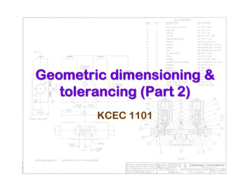
Example Determine the Toleranceusing The Hole Basis SystemSolution: STEP 3 (For Hole):– Determine the upper and lower limits of thehole from ANSI Standard B4.2-1978 tables.Using column H7 and row 40– From the table, the limits are 40.025 and40.000
Example Determine the Toleranceusing The Hole Basis SystemSolution: STEP 4 (For Shaft):– Determine the upper and lower limits of theshaft from ANSI Standard B4.2-1978 tables.Using column g6 and row 40.– From the table, the limits are 39.991 and39.975
NEXT continue to GDT 3
Geometric dimensioning & tolerancing (Part 2) KCEC 1101. Tolerances Geometric tolerances are controls that effect the shape and/or orientation of features. Tolerance is the total amount a dimension may vary and