Transcription
SparkFun Environmental Sensor Breakout - BME680 (Qwiic)Hookup GuideIntroductionThe SparkFun Environmental Sensor - BME680 (Qwiic) is a breakout for the 4-in-1 BME680 gas sensor fromBosch. The BME680 combines a gas sensor with temperature, humidity and barometric pressure sensing for acomplete environmental sensor in a single package. The gas sensor on the BME680 can detect a wide variety ofvolatile organic compounds (or VOC for short) to monitor indoor air quality. Combine that with precise temperature,humidity and barometric pressure and the BME680 can work as a completely standalone environmental sensor allin a 1"x1" breakout! The BME680 communicates over either I2C or SPI. As you would expect from the name, theBME680's I2C pins are broken out to a Qwiic connector so integrating it into the SparkFun Qwiic System is abreeze. Simply plug it into a Qwiic-enabled microcontroller and you're well on your way to making your ownweather station.SparkFun Environmental Sensor Breakout - BME680(Qwiic) SEN-16466Product Showcase: SparkFun Qwiic Environmental Sensor Break Break
Required MaterialsTo follow along with this guide you will need a microcontroller to communicate with the BME680. Below are a fewoptions that come Qwiic-enabled out of the box:SparkFun Thing Plus - ESP32 WROOM WRL-15663SparkFun Qwiic Pro Micro - USB-C(ATmega32U4) DEV-15795SparkFun RedBoard QwiicSparkFun RedBoard Artemis DEV-15123 DEV-15444If your chosen microcontroller is not already Qwiic-enabled, you can add that functionality with one or more of thefollowing items:
SparkFun Qwiic Cable KitSparkFun Qwiic Shield for Arduino KIT-15081 DEV-14352SparkFun Qwiic AdapterSparkFun Qwiic Shield for Arduino Nano DEV-14495 DEV-16130You will also want at least one Qwiic cable to connect your sensor to your microcontroller.Qwiic Cable - 100mmQwiic Cable - 200mm PRT-14427 PRT-14428Qwiic Cable - 500mmQwiic Cable - 50mm
PRT-14429 PRT-14426Suggested ReadingIf you are not familiar with the Qwiic system, we recommend reading here for an overview:Qwiic Connect SystemWe would also recommend taking a look at the following tutorials if you aren't familiar with the concepts covered inthem.Serial Peripheral Interface (SPI)I2CSPI is commonly used to connect microcontrollers toperipherals such as sensors, shift registers, and SDcards.An introduction to I2C, one of the main embeddedcommunications protocols in use today.Serial Terminal BasicsThis tutorial will show you how to communicate withyour serial devices using a variety of terminal emulatorapplications.Hardware Overview
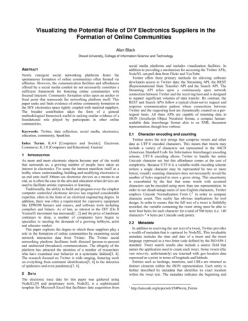
The heart of this breakout, Bosch's BME680 Gas Sensor, integrates four sensors (gas, pressure, temperature andhumidity) into a tiny package. The BME680 measures just 3mm x 3mm x 0.93 mm and was specifically designedfor applications that depend on a small footprint and low power consumption. This makes the BME680 a greatchoice for remote or mobile environmental sensing applications. We will highlight some of the unique aspects ofthe BME680 in this section but for a full overview of the sensor package, check out the Datasheet.PowerThe BME680 accepts a supply voltage between 1.71 to 3.6V. Power can be supplied to the board either throughone of the Qwiic connectors or the dedicated 3.3V and GND pins broken out on either side of the board.Qwiic and I2C InterfaceThe SparkFun Environmental Sensor - BME680 (Qwiic) communicates over I2C by default. We have routed theBME680's I2C pins to two Qwiic connectors as well as broken them out to 0.1"-spaced the header pins highlightedbelow.Serial Peripheral Interface (SPI)
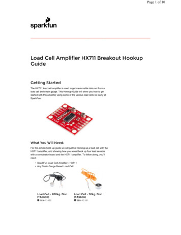
If you would prefer to communicate with your BME680 via SPI, we have broken those pins out as well to standard0.1"-spade header pins. Communicating over SPI requires more connections than I2C but is more versatile andcan be faster. It is particularly helpful if you need to use more than two BME680's in your circuit or if you haveother devices using the same I2C addresses.JumpersThe SparkFun Environmental Sensor - BME680 (Qwiic) has three solder jumpers which can be modified to alterthe functionality of the sensor.If you have never worked with solder jumpers or PCB traces before or would like a refresher, take a look atour How to Work with Jumper Pads and PCB Traces tutorial.I2C Pull-Up JumperThe SDA/SDI and SCL/SCK pins are pulled to VDDIO (3.3V) through a pair of 4.7k Ohm resistors. The jumper isnormally closed so to disable the pull-up resistors, simply sever the traces between the three pads using a hobbyknife.
Power LED JumperThis jumper connects the power LED to 3.3V via a 1K Ohm resistor. This jumper is normally closed so to disablethe power LED, sever the trace between the two pads. This is particularly helpful for reducing the total currentdraw of your breakout for low-power applications.I2C Address JumperThis jumper sets the 7-Bit unshifted I2C address of the BME680 and is open by default. The default address is0x77 and can be adjusted to 0x76 by closing this jumper.Board DimensionsThis breakout fits the Qwiic standard sizing for breakouts. It is a 1"x1" square with two mounting holes that fit a 440 screw.
Now that we have a thorough understanding of the hardware and features on the Environmental Sensor - BME680(Qwiic), it's time to hook it up and start taking measurements.Hardware HookupUsing the Qwiic system, assembling the hardware is simple. All you need to do is connect your EnvironmentalSensor - BME680 (Qwiic) to your chosen development board with a Qwiic cable or adapter cable. Otherwise, youcan use the I2C pins broken out if you do not have a Qwiic connector on your development board or if you do notwant to use a Qwiic connection. If you are not using a Qwiic-enabled board, make sure your input voltage andlogic are either running at 3.3V or you are shifting the logic level from whatever logic your controller runs at to 3.3Vfor the BME680.If you would prefer to communicate with the BME680 via SPI, you will need to connect to the SPI pins broken outon this board and route them to the respective pins for SPI communication on your development board (MISO,MOSI, SCK and CS/SS). Also note that this breakout defaults to I2C mode so your code will need to toggle the CSpin LOW once on power up to enable SPI mode. The BME680 will remain in SPI mode until the next power cycle.The SPI examples further on in this guide do that automatically so it's only necessary to note for writing your owncode.Soldering to the pins is the best option for a secure connection but you can also create temporary connections tothose pins for prototyping using something like these IC Hooks. If you are not familiar with through-hole soldering,take a look at this tutorial:
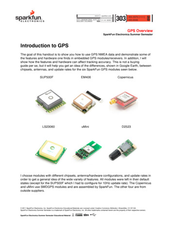
How to Solder: Through-Hole SolderingSEPTEMBER 19, 2013This tutorial covers everything you need to know about through-hole soldering.With everything connected properly, we're ready to move on to uploading a sketch and start monitoring yourenvironment!BME680 Arduino LibraryNote: This library assumes you are using the latest version of the Arduino IDE on your desktop. If this is yourfirst time using Arduino, please review our tutorial on installing the Arduino IDE. If you have not previouslyinstalled an Arduino library, please check out our installation guide.For the scope of tutorial, we are going to use the BME680 Arduino Library created by SV-Zanshin. You candownload it with the Arduino Library Manager by searching 'BME680' and selecting the one authored by SVZanshin. Alternatively, you can grab the zip of the latest release (v1.0.3 as of this writing) below or you candownload the most up to date version of the library from the GitHub repository.BME680 ARDUINO LIBRARY (ZIP)Once you have the library installed you can move on to uploading the examples and gathering environmental data.Arduino ExamplesNow that the library is installed, we can move on to uploading some code. Before we discuss the individualexamples, we'll cover some of the setup they perform for the BME680.The code configures the BME680 to perform oversampling for the temperature, humidity and pressure sensorsand sets an IIR (infinite impulse response) filter for these sensors. This helps smooth out environmental data fromany short term outliers. Finally, the setup also configures the temperature and time settings for the hot plate on thegas sensor. If you would like to adjust any of these settings, refer to the BME680 Datasheet and the library sourcefiles for more information.I2C DemoTo open this example, head to File Examples BME680 I2CDemo. Next, open the Tools menu and selectyour board (in our case, Arduino Uno) and the correct Port your board enumerated on.Upload the code, open the Arduino Serial Monitor and set your baud rate to 115200. You probably will see thecode print out the successful initialization of the BME680 as well as the settings we discussed above and afterthat, you should see temperature, humidity, pressure, altitude and raw gas readings every five seconds.
SPI DemoThis example is nearly identical to the I2C demo but instead uses SPI mode. One thing to note is, depending onwhich type of microcontroller you are using, you may need to adjust this line:const uint8 tSPI CS PIN 53;Set the CS/SS pin to the appropriate pin on your microcontroller. In our case, the Uno uses D10 for CS so themodified version of that line for an Uno or SparkFun RedBoard Qwiic would be:const uint8 tSPI CS PIN 10;With that line adjusted, upload the code and open your serial monitor. You should see a similar stream of data asthe screenshot above for the I2C example.Tip: If you'd like to use this library with a development board with multiple serial ports like the RedBoardTurbo we show in the Hardware Hookup section, you'll want to add this line: #define Serial SerialUSBprior to your void setup() . This definition can be modified to any serial port on your chosen microcontroller.TroubleshootingIn this section we'll cover a few tips and tricks for troubleshooting common questions with the EnvironmentalSensor Breakout - BME680.Gas Readings InterpretationThe library used in this tutorial only prints out the raw resistance values from the gas sensor on the BME680. Youcan use these values as a rough estimate of air quality where lower resistance values equate to a higherconcentration of gases measured (and vice versa). If you want to get true Indoor Air Quality (IAQ) measurementsfrom the BME680, we recommend taking a look at Bosch's BSEC Arduino Library which includes an algorithm toconvert the resistance value to an IAQ value. For more information, refer to that library as well as sections 1.2 and4.2 in the BME680 Datasheet. Calculated IAQ measurements are beyond the scope of this tutorial.Incorrect Temperature DataYou may notice some deviation from the true ambient temperature in your data as residual heat from the hot platefor the gas sensor in the BME680 can cause minor fluctuations in the observed temperature. The heating phasestarts after temperature, pressure and humidity measurements are complete so there should be no heating duringthose measurements but subsequent readings may be skewed. The IIR filters can help here but if needed, youcan compensate for this by measuring the average deviation and subtracting that from your temperature data.Incorrect Altitude Data
The altitude data is collected by converting the barometric pressure. This is a great tool for approximate altitudereadings but things like weather patterns can affect the accuracy of the altitude. The examples use the standardmeasurement for pressure at sea level (1013.25 hPa) in the calculation so you may wish to adjust that with acorrected value for a more accurate altitude data. Refer to this Wikipedia page and this section of our MPL3115Pressure Sensor Hookup Guide for more information.Chip Select DefinitionAs we covered in the previous section, if you choose to communicate with the BME680 via SPI, make sure you areconnecting to the correct pins on your development board (MOSI, MISO, SCK and CS) as well as modifying theChip Select/Slave Select definition to the appropriate I/O pin used for CS on your controller. If you are not certainwhich pin is used for CS, refer to documentation for your particular development board. Need help with something not covered here?If your product is not working as you expected or you need technical assistance or information, head on overto the SparkFun Technical Assistance page for some initial troubleshooting.If you don't find what you need there, the SparkFun Forums are a great place to find and ask for help. If thisis your first visit, you'll need to create a Forum Account to search product forums and post questions.Resources and Going FurtherNow that your BME680 is integrated in your circuit and sending data it's time to start tracking some weather! Formore information about this breakout and the BME680, take a look at the links below:Schematic (PDF)Eagle Files (ZIP)Board Dimensions (PNG)Datasheet (PDF)Layout Considerations (PDF)Hardware GitHub RepositoryBME680 Arduino Library GitHub RepositoryBosch BSEC Arduino Library GitHub RepositoryNeed some inspiration for your next project? Check out some of these weather sensing related tutorials:SparkFun Inventor's Kit for Photon ExperimentGuideDive into the world of the Internet of Things with theSparkFun Inventor's Kit for Photon.SparkFun BME280 Breakout Hookup GuideA guide for connecting the BEM280 sensor to amicrocontroller, and for using the Sparkfun Arduinolibrary.
ESP32 Environment Sensor Shield HookupGuideSparkFun's ESP32 Environment Sensor Shieldprovides sensors and hookups for monitoringenvironmental conditions. This tutorial will show youhow to connect your sensor suite to the Internet andpost weather data online.Weather Meter Hookup GuideHow to assemble your very own weather meter!
The SparkFun Environmental Sensor - BME680 (Qwiic) is a breakout for the 4-in-1 BME680 gas sensor from Bosch. The BME680 combines a gas sensor with temperature, humidity and barometric pressure sensing for a . MOSI, SCK and CS/SS). Also note that this breakout defaults to I C mode so your code will need to toggle the CS pin LOW once on power .