Transcription
MEM 201Fundamentals of Computer Aided DesignGeometrical Dimensioning &Tolerancing (GD&T)Department of Mechanical Engineering and Mechanics
Today’s Objectives . Tolerances and why do we need them. Different types of tolerances. To learn how to effectively tolerance partsin engineering drawings. Allowance/Clearance Expressing tolerances in AutoCAD.Department of Mechanical Engineering and Mechanics
Tolerancing Definition: “Allowance for a specific variation in the size andgeometry of part.” Why is it needed: No one or thing is perfect ! Hence, engineers have come up with a way to make thingsclose to perfect by specifying Tolerances !– Since variation from the drawing is inevitable theacceptable degree of variation must be specified.– Large variation may affect the functionality of the part– Small variation will effect the cost of the part requires precise manufacturing. requires inspection and the rejection of parts.Department of Mechanical Engineering and Mechanics
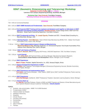
When does Tolerances become important Assemblies: Parts will often not fit together if theirdimensions do not fall with in a certain range of values. Interchangeability: If a replacement part is used it must bea duplicate of the original part within certain limits ofdeviation. The relationship between functionality and size or shapeof an object varies from part to part.Tolerances do not affect its functionDepartment of Mechanical Engineering and MechanicsTolerances are important here !
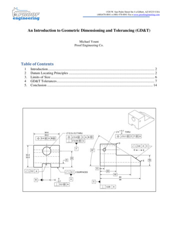
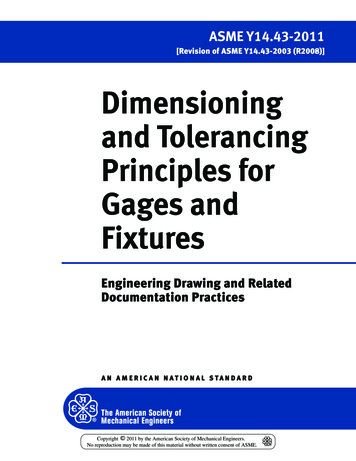
Food for thought: Tolerance levels in this mechanism?Department of Mechanical Engineering and Mechanics
Tolerance in relation to Cost generally increases with smaller tolerance– Small tolerances cause an exponential increase in cost– Therefore your duty as an engineer have to consider : Doyou need Φ1.0001in or is 1.01in good enough? Parts with small tolerances often require special methods ofmanufacturing. Parts with small tolerances often require greater inspectionand call for the rejection of partsGreater QualityInspectionGreater cost. Do not specify a smaller tolerance than is necessary!Department of Mechanical Engineering and Mechanics
How are Tolerances Specified Size– Limits specifying the allowed variation in eachdimension (length, width, height, diameter,etc.) are given on the drawing Geometry– Geometric Tolerancing Allows for specification of tolerance for thegeometry of a part separate from its size GDT (Geometric Dimensioning and Tolerancing)uses special symbols to control different geometricfeatures of a partDepartment of Mechanical Engineering and Mechanics
Value of Tolerance The tolerance for a single dimension may be specifiedwith the dimension and then the tolerance.– The tolerance is total variation between the upper and lowerlimits.Department of Mechanical Engineering and Mechanics
General Tolerances These are specified when all dimension in the drawingshave the same tolerance. These notes are used to reduce the number ofdimensions required on a drawing and to promotedrawing clarity.12Department of Mechanical Engineering and Mechanics
Tolerances specified for size Limit Tolerances – (12.75/12.25 ) Plus/Minus Tolerances– Unilateral Tolerances - (12.00 or - xxx)– Bilateral Tolerances - (12.00 xxx/- xxx)These tolerance values indicate the:MMC: Maximum Material ConditionLMC: Least Material ConditionDepartment of Mechanical Engineering and Mechanics
Limit TolerancesMMC: Maximum Material ConditionLMC: Least Material ConditionDepartment of Mechanical Engineering and Mechanics
Limit TolerancesDepartment of Mechanical Engineering and Mechanics
Plus/Minus TolerancesDepartment of Mechanical Engineering and Mechanics
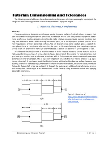
Allowance and Clearance ALLOWANCEAllowance is defined as an intentional difference between the maximummaterial limits of mating parts. Allowance is the minimum clearance (positiveallowance), or maximum interference (negative allowance) between matingparts. The calculation formula for allowance is:ALLOWANCE MMC HOLE – MMC SHAFT CLEARANCEClearance is defined as the loosest fit or maximum intended differencebetween mating parts.The calculation formula for clearance is:CLEARANCE LMC HOLE – LMC SHAFTDepartment of Mechanical Engineering and Mechanics
Types of Fit Types of Fit– Clearance fit The parts are toleranced such that the largest shaft issmaller than the smallest hole The allowance is positive and greater than zero– Interference fit The max. clearance is always negative The parts must always be forced together– Transition fit The parts are toleranced such that the allowance isnegative and the max. clearance is positive The parts may be loose or forced togetherDepartment of Mechanical Engineering and Mechanics
BASIC FITS OF MATING PARTSStandard ANSI Fits:Running and Sliding fits (RC) are intended to provide a runningperformance with suitable lubrication allowance. The range is from RC1 toRC9.Force fits (FN) or Shrink fits constitute a special type of interference fitcharacterized by maintenance of constant pressure. The range is from FN1to FN5.A force fit is referred to as interference fit or a shrink fit. The smallestamount of interference is:MIN INTERFERENCE LMC SHAFT - LMC HOLEThe greatest amount of interference is:MAX INTERFERENCE MMC SHAFT - MMC HOLELocational fits are intended to determine only the location of the matingparts.Department of Mechanical Engineering and Mechanics
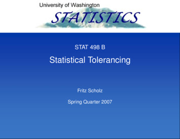
Sample CalculationGiven: Diameter of shaft: 1.5mmUpper Limit Tolerance: 0.03mmLower Limit Tolerance : 0.04mmGiven: Diameter of Hole: 1.48mmUpper Limit Tolerance : 0.03mmLower Limit Tolerance : 0.05mmAllowance: MMC-Hole - MMC-Shaft 1.43 – 1.53 - 0.1mmClearance: LMC-Hole – LMC-Shaft 1.51 – 1.46 0.05mmDepartment of Mechanical Engineering and MechanicsAnswerAllowance: -0.1mmClearance: 0.05mmType of Fit: Transition Fit
Geometric Dimensioning & Tolerancing(GD&T)Department of Mechanical Engineering and Mechanics
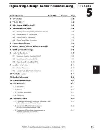
Tolerance of FormStraightnessStraightness Tolerance ZoneDepartment of Mechanical Engineering and MechanicsStraightness Tolerance
Tolerance of FormFLATNESSNote: 0.16 0.5 (size tolerance)Department of Mechanical Engineering and Mechanics
Tolerance of FormCircularityCircularity Tolerance ZoneCircularity ToleranceDepartment of Mechanical Engineering and Mechanics
Tolerance of FormCylindricityCylindricity Tolerance ZoneCylindricity ToleranceDepartment of Mechanical Engineering and Mechanics
Tolerance of OrientationPerpendicularity Tolerance ZonePerpendicularityDepartment of Mechanical Engineering and MechanicsPerpendicularity Tolerance
Tolerance of OrientationParallelismParallelism Tolerance ZoneT: Tangent PlaneParallelism ToleranceDepartment of Mechanical Engineering and Mechanics
Tolerances in AutoCADDepartment of Mechanical Engineering and Mechanics
Tolerances in AutoCADDepartment of Mechanical Engineering and Mechanics
Tolerances in AutoCADDepartment of Mechanical Engineering and Mechanics
GEOMETRY DIMESIONING AND TOLERANCEFOR CADD/CAMSome dimensioning and tolerance guidelines for use in conjunction with CADD/CAM: Geometry tolerancing is necessary to control specific geometric form and location.Major features of the part should be used to establish the basic coordinate system, but are notnecessary defined as datum.Subcoordinated systems that are related to the major coordinates are used to locate and orientfeatures on a part.Define part features in relation to three mutually perpendicular reference plans, and along featuresthat are parallel to the motion of CAM equipment.Establish datum related to the function of the part, and relate datum features in order of precedenceas a basis for CAM usage.Completely and accurately dimension geometric shapes. Regular geometric shapes may be definedby mathematical formulas. A profile feature that is defined with mathematical formulas should nothave coordinate dimensions unless required for inspection or reference.Coordinate or tabular dimensions should be used to identify approximate dimensions on an arbitraryprofile.Use the same type of coordinate dimensioning system on the entire drawing.Continuity of profile is necessary for CADD. Clearly define contour changes at the change or point oftangency. Define at least four points along an irregular profile.Circular hole patterns may be defined with polar coordinate dimensioning.When possible, dimension angles in degrees and decimal parts of degrees.Base dimensions at the mean of a tolerance because the computer numerical control (CNC)programmer normally splits a tolerance and works to the mean. While this is theoretically desirable,one can not predict where the part will be made. Dimensions should always be based on designrequirements. If it is known that a part will be produced always by CNC methods, then establishdimensions without limits that conform to CNC machine capabilities. Bilateral profile tolerances arealso recommended for the same reason.Department of Mechanical Engineering and Mechanics
Further Reading Interpretation of Geometric Dimensioning & Tolerancing by Daniel E.Puncochar Geometric Dimensioning and Tolerancing by Alex Krulikowski Geo-Metrics III : The Application of Geometric Dimensioning andTolerancing Techniques (Using the Customary Inch Systems) byLowell W. Foster Tolerance design : a handbook for developing optimal specificationsby C.M. Creveling. Dimensioning and Tolerancing Handbook by Paul J. Drake Inspection and Gaging by Clifford W. Kennedy Geometric Dimensioning and Tolerancing by Cecil H. Jensen Tolerance Stack-Up Analysis by James D. MeadowsDepartment of Mechanical Engineering and Mechanics
Home Work #21. Find TH, Ts, Allowance, Cmax, Cmin, and what kind of fit it is ?Hole F 66 upper deviation 0.051, lower deviation 0.0Shaft F 66 upper deviation -0.024, lower deviation -0.0502. Find TH, Ts, Allowance , Cmax, Imax, and what kind of fit it is ?Hole F 32 upper deviation 0.021, lower deviation 0.0Shaft F 32 upper deviation 0.029, lower deviation 0.0163. If a shaft is 10 0.05 inch what is its maximum and least materialconditions.4. Please draw circularity and perpendicularity symbol blockswith geometric tolerance of 0.005 for each, and sketch theirtolerance zones for a cylinder and a upside down T shape blockrespectively.Department of Mechanical Engineering and Mechanics
Home Work #2 contd.Th tolerance of holeTs Tolerance of shaftCmax Maximum clearanceCmin Minimum clearanceImax Maxiumum interferenceF66 and F32 indicates the nominal dimensions of the hole or shaft Refer Notes and AutoCAD text book for help in solving problems. Home works should include your names and the section you belong to. Will be due during the next Lecture Class.Department of Mechanical Engineering and Mechanics
GDT (Geometric Dimensioning and Tolerancing) uses special symbols to control different geometric features of a part. Department of Mechanical Engineering and Mechanics Value of Tolerance The tolerance for a single dimension may be specified with the dimension and then the tolerance. – The tolerance is total variation between the upper and lower limits. Department of Mechanical .File Size: 501KBPage Count: 31