Transcription
DIMENSIONING & TOLERANCINGDeborah Munro, Ph.D.
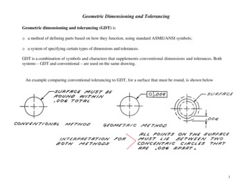
Overview: Why do we dimension?Why do we tolerance? Why GD&T? Most machining, assembly, and construction is stilldone while not in front of a CAD modelProvides information to the machinist as to ourdesign intentProvides information as to how critical a dimensionis to the design intentProvides information that cannot be conveyed by aCAD modelProvides geometric intent not conveyed elsewhere
Basic Dimensioning Rules A dimension can only be called out once.Smaller lengths should be closer to the part, largerones farther out.Dimension from one side or a key location (holecenter) to avoid error stack up.Do not dimension to hidden lines! Use section views as needed to avoid thisDimensions should be logically laid out andgrouped by featuresDimension only on part drawings, not assemblies
Basic Tolerancing Rules Use the default tolerance blocks as much aspossible, with decimal places for tolerancingBe as generous as possible with your tolerancesUse non-symmetric tolerancing to show design intentWhen in doubt, ask a machinist what tolerancesthey can hold!
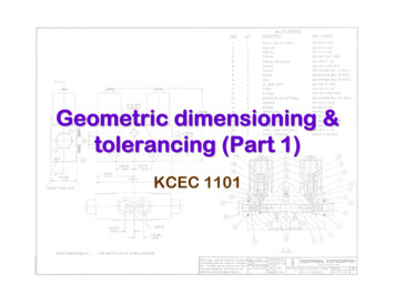
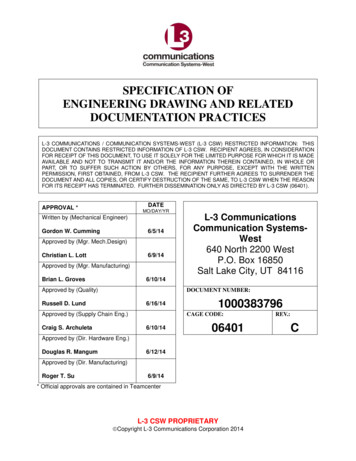
Types of Dimensions
Geometric Dimensioning & Tolerancing Used when it’s “not the tolerance” that you want tocontrolParallel, Perpendicular, Concentric, Flat, PositionRequires a datum referenceRequires a tolerance on GD&TModifiers: MMC, LMChttp://en.wikipedia.org/wiki/Geometric dimensioning and tolerancing
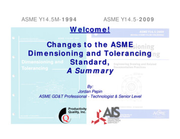
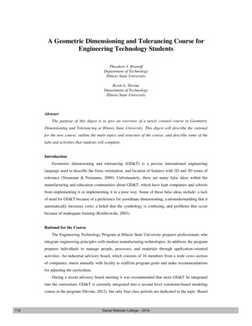
Example: Pistons
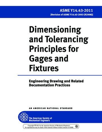
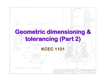
(True) Position
Definition of Positional TolerancePositional tolerance controls the location of an axis, median plane or surface of a feature. Thisis a term used for the positioning of cylindrical features (holes, shafts etc.), Line features, Pointfeatures and Slot features etc. These features are always related to basic dimensions or datumwithin the stated tolerance and generally at maximum material condition (MMC).Positional tolerance is normally used for the interchangeability characteristic of non-spinningmating parts for maximum productivity. It defines a zone within which the axis, median plane orsurface of a feature is permitted to vary from a true position.True position is established with basic dimensions from a datum reference frame or from otherfeatures that are related to the datum reference frame. All dimensions must be basic and areconsidered theoretically exact. The tolerance for the deviation of the feature from basic is foundin the position feature control frame.
Summary Only dimension onceDimension everythingTolerance beyond decimal places only whenneededUse GD&T to control things tolerances won’tUse notes and callouts when appropriateDon’t dimension to hidden linesProvide overall part size reference dimensions
Geometric Dimensioning & Tolerancing Used when it’s “not the tolerance” that you want to co