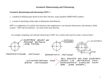
Transcription
A Geometric Dimensioning and Tolerancing Course forEngineering Technology StudentsTheodore J. BranoffDepartment of TechnologyIllinois State UniversityKevin L. DevineDepartment of TechnologyIllinois State UniversityAbstractThe purpose of this digest is to give an overview of a newly created course in GeometricDimensioning and Tolerancing at Illinois State University. This digest will describe the rationalfor the new course, outline the main topics and structure of the course, and describe some of thelabs and activities that students will complete.IntroductionGeometric dimensioning and tolerancing (GD&T) is a precise international engineeringlanguage used to describe the form, orientation, and location of features with 2D and 3D zones oftolerance (Neumann & Neumann, 2009). Unfortunately, there are many false ideas within themanufacturing and education communities about GD&T, which have kept companies and schoolsfrom implementing it or implementing it in a poor way. Some of these false ideas include: a lackof need for GD&T because of a preference for coordinate dimensioning; a misunderstanding that itautomatically increases costs; a belief that the symbology is confusing; and problems that occurbecause of inadequate training (Krulikowski, 2003).Rational for the CourseThe Engineering Technology Program at Illinois State University prepares professionals whointegrate engineering principles with modern manufacturing technologies. In addition, the programprepares individuals to manage people, processes, and materials through application-orientedactivities. An industrial advisory board, which consists of 16 members from a wide cross sectionof companies, meets annually with faculty to reaffirm program goals and make recommendationsfor adjusting the curriculum.During a recent advisory board meeting it was recommended that more GD&T be integratedinto the curriculum. GD&T is currently integrated into a second level constraint-based modelingcourse in the program (Devine, 2012), but only four class periods are dedicated to the topic. Based110Daniel Webster College – 2016
on feedback from the industry advisory board, a new elective course was developed and is beingtaught for the first time during the Fall 2016 semester.Outline of CourseThe three credit hour course was designed to give students an overview of the basicterminology used in GD&T, opportunities to apply GD&T in a design setting for modestlycomplex parts, activities where students apply GD&T within a CAD environment, andlaboratories where students inspect parts using calipers and coordinate measuring machines(CMM). The class meets twice each week for 1 hour and 50 minutes. The maximum capacity is 30students, but enrollment for the Fall 2016 semester is currently at 12. Prerequisites include thecourse on manufacturing processes (basic measurement methods, plastics, milling, turning,shearing, casting, hot forming, cold forming, sheet metal, additive manufacturing techniques, andwelding) and the second level constraint-based modeling course (parts, drawings, and assembliesin Siemens NX; introduction to dimensioning and tolerancing; and advanced working drawings).Specific learning outcomes for the course include: identify the geometric characteristic symbolsand other symbols associated with geometric dimensioning and tolerancing; identify features withsize and features without size; specify limit dimensions within a given design scenario; calculatethe virtual condition for features; determine the advantages of using different material conditionmodifiers; apply appropriate datum reference frames to designs; apply appropriate geometrictolerances to designs; and execute proper inspection set-ups and procedures for checkinggeometric tolerances. The main source for the content knowledge in the course is GeoTol Pro: APractical Guide to Geometric Tolerancing per ASME Y14.5 – 2009 (Neumann & Neumann,2009). Table 1 shows a general layout of the daily topics, quizzes, and labs in the course.To assess the entry level content knowledge of students in the course, a pretest was givenduring the first class. Topics on the pretest were selected to provide a broad range of materialrelated to GD&T. It included questions related to the following areas: Identifying current standards related to dimensioning and tolerancing. Giving a drawing, label symbols (all around, countersink, datum feature, basic dimension, etc.). Given a drawing, label the dimensions referring to a feature with size. Given a drawing: identify the MMC of a specified hole; the amount of tolerance allowed if aboss/hole is produced at a certain size; and label the datum reference frame origin. Given a drawing with a profile tolerance applied, identify the type of the profile tolerance(bilateral-equal, bilateral-unequal, unilateral-in, and unilateral-out). Given a drawing, sketch datum feature symbols per descriptions.71st EDGD Mid Year Proceedings111
Given a drawing with position tolerances, calculate virtual sizes. Given a sentence description of a composite position tolerance, sketch the feature control frame. Given a nominal size, specified fit (e.g., RC2), and a fit table, write out the limit dimension for ahole and pin system.Table 1. Outline of GD&T Course.Week123TopicOrientation / Safety discussionIntroduction to GD&TLimit Dimensioning / Limits of SizeLab ActivityHow the GD&T System WorksLab Activity4Position Tolerance Verification56789101112Lab ActivityProduction Plans and Virtual ConditionTEST 1The Datum Reference FrameLab ActivityLab dayForm TolerancesOrientation TolerancesEDGD ConferenceProfile TolerancesLab ActivityDatum Feature ModifiersTEST 2The Datum Reference Frame II – Targets IrregularSurfacesLab ActivityThe Datum Reference Frame III – Advanced Concepts13Lab ActivityPosition Tolerances141516112Lab ActivityCoaxial ControlsFastener Formulas & Screw ThreadsFinal ExamDaniel Webster College – 2016AssignmentQuiz 1 – OnlineQuiz 2 – OnlineLAB 1 – Measuring withcalipersQuiz 3 – OnlineLAB 2 – Introduction to RomerArm LabLAB 3 – NX model/drawing ofPLATEQuiz 4 – OnlineLAB 4 – Excel table for pos.ver.LAB 5 – Romer Arm – PositionVerificationLAB 6 – NX model/drawing ofBRACKETQuiz 5 – OnlineReview ReadingsQuiz 6 – OnlineLAB 7 – Introduction to Brown& SharpeLAB 8 – Functional GageActivityContinue working on labsQuiz 7 – OnlineQuiz 8 – OnlineCatch up on assignmentsQuiz 9 – OnlineLAB 9 – Checking ProfileTolerancesLAB 10 – NX Lab for ProfileTolerancesQuiz 10 – OnlineReview ReadingsQuiz 11 – OnlineLAB 11 – Casting Drawings inNXQuiz 12 – OnlineLAB 12 – Pattern of Holes as aDatumQuiz 13 – OnlineLAB 13 – Checking CompositePositionQuiz 14
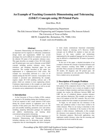
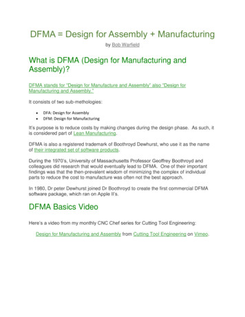
All of the items on the pretest will be assessed again at some point in the course. Test 1 willcover material from the first part of the course. Test 2 will assess the material between Test 1 andTest 2. The final exam will be comprehensive.Neumann & Neumann (2009) is a workbook style text that contains end-of-unit exercisesgeared toward industry professionals. Rather than evaluate students’ content knowledge bycollecting their workbooks each period, exercises are discussed in class and online quizzes of unitmaterial are administered through the university’s learning management system. Figures 1 & 2show examples of the types of assessment questions included in the course.Figure 1. Example Fill-in-the-Blank Question.Figure 2. Example Multiple-Choice Question.Lab activities were designed so that all students are engaged during lab days. This ischallenging since the program only has two CMMs. For example, LAB 2 and LAB 3 are bothintroduced on the same day. LAB 2 is an introduction to the Romer Arm CMM. This lab wasdesigned for groups of 2-3 students, so students rotate through the activity one group at a time.71st EDGD Mid Year Proceedings113
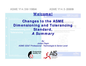
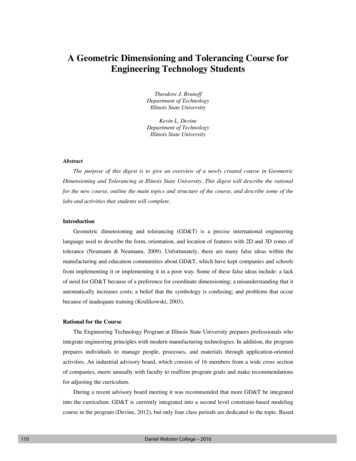
Simultaneously, the rest of class works on LAB 3, which involves creating a model and drawingof a part and applying GD&T.Examples of Labs in the CourseThe labs are designed to give students practical, hands-on application of the topics coveredduring the course. The first lab was designed to have each student measure parts with calipers toillustrate some of the potential problems with conventional coordinate dimensioning. The class isgiven 12 similar parts to measure with dial and/or digital calipers (Figures 3). In addition, adrawing is provided with the specified dimensions for the parts (Figure 4). Students are asked totake 2 measurements of 4 dimensions on each of the 12 parts and record their values on the labtable (Figure 5). They are then asked to graphically represent their data collection using an Exceltable for each of the 4 dimensions (Figure 6). The last section of the lab requires students to makedecisions about whether or not they would accept or reject each part and give reasons why if a partis rejected.Figure 3. Example of LAB 1 Part.Figure 4. Drawing of LAB 1 Part.114Daniel Webster College – 2016
Figure 5. LAB 1 Table.Figure 6. LAB 1 Data Example.Students also complete labs on both Romer Arm and Brown & Sharpe coordinate measuringmachines. In addition to gaining practical experience operating a CMM, these labs help toillustrate the power and consistency of GD&T within well thought out datum reference frames.Figures 7-10 illustrate the set-up, feature location, and report generation for inspecting thepreviously used block using a Romer Arm and PC-DMIS software.Figure 7. Romer Arm Set-Up of Part.71st EDGD Mid Year Proceedings115
Figure 8. Feature Location within PC-DMIS.Figure 9. Example of Final Evaluation within PC-DMIS.116Daniel Webster College – 2016
Figure 10. PC-DMIS Final Inspection Report.ConclusionsSince the course is being offered for the first time during the Fall 2016 semester, a fullevaluation is not available at the time of this publication. A comprehensive pretest wasadministered at the beginning of the semester, which will be formally compared to the results ofthe two tests and the final exam. In addition, students will be surveyed at the end of the semesterto gain their feedback and thoughts on the course.ReferencesASME (2009). Dimensioning and Tolerancing, ASME Y14.5-2009. NY: American Society ofMechanical Engineers. 2009. ISBN 0-7918-3192-2.Devine, K. L. (2012). Dimensional tolerances: Back to the basics. Proceedings of the 66thMidyear Conference of the Engineering Design Graphics Division of the American Societyfor Engineering Education, Galveston, Texas, January 22-24, 2012.Krulikowski, A. (2003). Nine myths about geometric dimensioning and tolerancing. Quality, 42(10), 21-22.Neumann, S., & Neumann, A. (2009). GeoTol Pro: A practical guide to Geometric Tolerancing.Longboat Key, FL: Technical Consultants, Inc.71st EDGD Mid Year Proceedings117
Geometric dimensioning and tolerancing (GD&T) is a precise international engineering language used to describe the form, orientation, and location of features with 2D and 3D zones of tolerance (Neumann & Neumann, 20