Transcription
An Introduction to Arduino
An Introduction to ArduinoPDF GUIDE: http://antoinettejcitizen.com/files/AICCM Arduino.pdfMichelle WoulahanCreative media facilitator at City of MelbounreEvents listing: http://bit.do/techEventsAntoinette J. CitizenElectronic media artistWebsite: antoinettejcitizen.com
MicrocontrollersA microcontroller is a very small computer on a single integrated circuit (IC). All computers haveseveral things in common: CPU (central processing unit) that executes programs.RAM (random-access memory) where it can store variables.Input and output devices for interaction.Desktop computers are “general purpose computers” that can run any of thousands of programs.Microcontrollers are “special purpose computers.” Microcontrollers do one thing well.Microcontrollers are often embedded onto a single printed circuit board. This board provides allof the circuitry necessary for a useful control task. The intention is that the board is immediatelyuseful to an application developer, without them needing to spend time and effort in developing thecontroller hardware.BASIC StampMicrocontroller: Microchip Technology PIC Parallax SX processor.mbedMicrocontroller: ARM CortexIOIO OTGMicrocontroller: Microchip Technology PICArduinoMicrocontroller:Atmel AVR microcontroller ATmega8 ATmega168 ATmega328 ATmega1280 ATmega2560
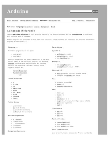
ArduinoSingle board microcontrollers like the Arduino are able to read inputs - light on a sensor, a finger on abutton, or a Twitter message - and turn it into an output - activating a motor, turning on an LED, publishingsomething online. Arduino is an open-source prototyping platform based on easy-to-use hardware andsoftware.Examples: no-2/There are lots of different types of Arduino boards. UNO is currently the most common and easily the bestdocumented and best supported of the Arduinos.ItemArduino Uno - R3Arduino LeonardoArduino ProArduino YunArduino MegaArduino Pro MiniArduino FioMicroControllerInputVoltageSystem Clock Digital AnalogFlashVoltage SpeedI/OInputs PWM V16MHz20*12732KbATmega3283.35 -12V3.3V5V8MHz146632KbATmega32u4Atheros 6MHz541614256KbATmega3285 - 12V5V16MHz148632KbATmega328P3.35 -12V3.3V8MHz148632Kb
Arduino-compatibleDF no
Single-board ComputersSingle board computers like the Raspberry Pi use application processors rather thanmicrocontrollers. These boards operated more like most computers you would normally use - youcan plug in a display, keyboard and mouse, and run an operating system and applications.Raspberry Pi 3Beagle board AM335x 1GHz ARM Cortex-A8512MB DDR3 RAM4GB 8-bit eMMC on-board flash storage3D graphics accelerator1 USB host2x 46 pin headersMini HDMI portEthernet portNEON floating-point accelerator2x PRU 32-bit microcontrollers Connectivity 1.2GHz 64-bit quad-core ARMv8 CPU1GB RAMMicro SD card slotVideoCore IV 3D graphics core4 USB ports40 GPIO pinsFull HDMI portEthernet portCombined 3.5mm audio jack andcomposite videoCamera interfaceDisplay interface802.11n Wireless LANBluetooth 4.1
Arduino uno: board layout
Sidekick components Breadboard x 1Green LED x 5Red LED x 5RGB Common Anode LED x 1Ceramic Capacitor(10nF x 10 100nF x 10)Aluminum capacitor(100uF x 5)Resistor(330R x 10 1k x 10 10k x 10)Tilt switch x 1Thermistor x 1 Photo resistor x 1Diode x 1Buzzer x 1Button x 5Switch x 5Mini Servo x 1Potentiometer with knob x 1Breadboard jumper wire x 25 (5x long, 20 xshort)
BreadboardsA breadboard is a solderless device for temporary prototype with electronics and test circuitdesigns. Electronic components can be interconnected by inserting their leads or terminals into theholes and then making connections through wires where appropriate. The breadboard has stripsof metal underneath the board and connect the holes on the top of the board. The metal strips arelaid out as shown below.Rows of the same number in colums A-Eand rows in columns F-J are connected.Power rail often used for positive andnegative(GND) voltage
First sketch: BlinkNegative Positive (longer leg)330 OHM Resistor(orange, orange, brown)Open sketch: File Examples Basic BlinkCreate an “int” variable called LED, set it to the corresponding arduino digital pin number.Change LED BUILTIN to LEDint LED 7;void setup() {pinMode(LED, OUTPUT);}void loop() {digitalWrite(LED, HIGH);delay(1000);digitalWrite(LED, LOW);delay(1000);}Now try changing the delay number to make LED blink faster or slower.
Resistor colour code
arduino intergrated development enviroment (ide)1. Verify: Compiles and approves your code. It will catch errors in syntax (like missing semicolonsor parentheses).2. Upload: Sends your code to the 101 board.3. New: This buttons opens up a new code window tab.4. Open: This button will let you open up an existing sketch.5. Save: This saves the currently active sketch.6. Serial Monitor: This will open a window that displays any serial information your 101 board istransmitting. It is very useful for debugging.7. Sketch Name: This shows the name of the sketch you are currently working on.8. Code Area: This is the area where you compose the code for your sketch.9. Message Area: This is where the IDE tells you if there were any errors in your code.10. Text Console: The text console shows complete error messages. When debugging, the textconsole is very useful.11. Board and Serial Port: Shows you what board and the serial port selections.
Select Your Board: Arduino/Genuino UNOBefore we can start jumping into the experiments, there are a few adjustments we need to make.This step is required to tell the Arduino IDE which of the many Arduino boards we have. Go up tothe Tools menu. Then hover over Board and make sure Arduino/Genuino UNO is selected.Select a Serial PortNext up we need to tell the Arduino IDE to which of our computer’s serial ports the 101 isconnected. Again,, go up to Tools, hover over Port, and select your 101’s serial port. This willhave Arduino 101 next to the port number in parentheses.Window Users: This is likely to be COM3 or higher (COM1 and COM2 are usually reserved forhardware serial ports). If there are multiple COM ports available, the UNO is likely the highestnumbered port in the list. To be certain, you can also disconnect your UNO and reopen themenu; the entry that disappears should be the UNO. Reconnect the board and select that serialport.Mac Users: Select the serial device of the UNO from the Tools, then hover over Port. On theMac, this should be something with /dev/tty.usbmodem or /dev/tty.usbserial in it.
Multiple BlinKsWe will edit the previous sketch to add two more LED variables.Add two new int for the twoadded LEDs.int LED 9;int LED2 10;int LED3 11;void setup() {pinMode(LED, OUTPUT);pinMode(LED2, OUTPUT);pinMode(LED3, OUTPUT);Add pinMode for the twoadded LEDs.}void loop() {digitalWrite(LED, HIGH);digitalWrite(LED2, HIGH);digitalWrite(LED3, HIGH);Add digitalwrite HIGH and LOWsequence for all LEDsdelay(1000);digitalWrite(LED, LOW);digitalWrite(LED2, LOW);digitalWrite(LED3, LOW);}delay(1000);
fadeWe use anaologWrite(pin number,0-255) rather than digitalWrite(pin number,HIGH/LOW)in order to change the brightness of the LED. 0 being off and 255 being the brightess.AnalogWrite only works with PWM pins - on the Arduino UNO PWM are pins 3,5,6,9,10,11.Learn more about PWM here - https://www.arduino.cc/en/Tutorial/PWMMake sure you connect to a PWM pin! Open sketch: File Examples Basic Fadeint led 9;// the PWM pin the LED is attached toint brightness 0; // how bright the LED isint fadeAmount 5; // how many points to fade the LED byvoid setup() {pinMode(led, OUTPUT);}void loop() {analogWrite(led, brightness); // set the brightness of pin 9:brightness brightness fadeAmount;}if (brightness 0 brightness 255) {fadeAmount -fadeAmount;}delay(30);
button input Open sketch: File Examples Digital Buttonconst int buttonPin 2;const int ledPin 13;// the number of the pushbutton pin// the number of the LED pin// variables will change:int buttonState 0;// variable for reading the pushbutton statusvoid setup() {// initialize the LED pin as an output:pinMode(ledPin, OUTPUT);// initialize the pushbutton pin as an input:pinMode(buttonPin, INPUT);}void loop() {buttonState digitalRead(buttonPin); // read the state of the pushbutton value:}// check if the pushbutton is pressed.// if it is, the buttonState is HIGH:if (buttonState HIGH) {// turn LED on:digitalWrite(ledPin, HIGH);} else {// turn LED off:digitalWrite(ledPin, LOW);}
SHieldsShields are boards that can be plugged on top of the Arduino PCB extending its capabilities.Ethernet ShieldGPS shieldAudio ShieldMotor ShieldProto Shield
Library ManagerLibraries are a collection of code that makes it easy for you to connect to a sensor, display,module, etc. For example, the built-in LiquidCrystal library makes it easy to talk to characterLCD displays. There are hundreds of additional libraries available on the Internet for download.To install a new library into your Arduino IDE you can use the Library Manager (available fromIDE version 1.6.2). Open the IDE and click to the “Sketch” menu and then Include Library Manage Libraries.You can also manually install libraries that are not available in the manager by copying thelibrary folder into Documents Arduino libraries
servoServos have integrated gears and a shaft that can be precisely controlled. Standard servos allowthe shaft to be positioned at various angles, usually between 0 and 180 degrees. As the servomotor already contains a driver circuit, it is easy to control with an Arduino - no other circuitryrequired!Applications: Robotics Animatronics Radio Control Cars/Boats/PlanesAdvantages: Low cost Variety - There is a wide range of sizes and torqueratings Simple to control using Arduino Up to 12 servos can be connecting using theArduino servo libraryLimitations: Limited range of motion - Most servos are limited to180 degrees of motion. Moderate precision - Positioning accuracy and repeatability of /- 1 degree is typical. Jitter - The feedback mechanism in the servo will actively try to correct any drift from the targetposition. This constant adjustment can create annoying twitches while trying to hold a steadyposition. If this is a problem for your application, consider a stepper motor instead.
Some interesting projects using servos:The Plot Clock - https://www.youtube.com/watch?v NiGG9Lcrni8Arduino Hexapod - https://www.youtube.com/watch?v 4a5R4umrRpARobotic Arm - https://www.youtube.com/watch?v B2fl8-L6xcATeaching Robot - https://www.youtube.com/watch?v bLnAJ-mSElEConnecting to Arduino:Servo motors have three wires: power, ground, and signal.The power wire is typically red, and should be connected to the 5V pinon the Arduino board.The ground wire is typically black or brown and should be connected toa ground pin on the Arduino board.The signal pin is typically yellow, orange or white and should beconnected to a digital pin on the Arduino board.180 Ground (GND)Power (5V)Signal (digital pin)
Controlling a servo:The sketch below is an example from the Arduino IDE. EXAMPLES SERVO SWEEPThis code uses the Servo library, you can learn more about this library here https://www.arduino.cc/en/Reference/ServoThis sketch will “sweep” the servo motor by going through every position (0 - 180) and backagain with 15 millisecond delay between each position.#include Servo.h Servo myservo; // create servo object to control a servo// twelve servo objects can be created on most boardsint pos 0;// variable to store the servo positionvoid setup() {myservo.attach(9); // attaches the servo on pin 9 to the servo object}void loop() {for (pos 0; pos 180; pos 1) { // goes from 0 degrees to 180 degrees// in steps of 1 degreemyservo.write(pos);// tell servo to go to position in variable ‘pos’delay(15);// waits 15ms for the servo to reach the position}for (pos 180; pos 0; pos - 1) { // goes from 180 degrees to 0 degreesmyservo.write(pos);// tell servo to go to position in variable ‘pos’delay(15);// waits 15ms for the servo to reach the position}}Try replacing the void loop function with the following:void loop() lay(500);}// tell servo to go to position ‘0’// wait 500ms// tell servo to go to position ‘100’// wait 500msInstead of sweeping through every position as per the previous example, the above code willmake the servo go from position 0 to position 100 as fast as it can. A longer delay is required asthe servo needs time to get to its position before the next position signal is sent; otherwise thenew position will overwrite the previously sent position and it servo will behave erratically.
Controlling a servo with a potentiometer:A potentiometer is a simple knob that provides a variable resistance, which we can read intothe Arduino board as an analog value. By turning the shaft of the potentiometer, we changethe amount of resistance on either side of the wiper which is connected to the center pin of thepotentiometer. This changes the relative “closeness” of that pin to 5volts and ground, giving us a different analog input. When the shaftis turned all the way in one direction, there are 0 volts going to thepin, and we read 0. When the shaft is turned all the way in the otherdirection, there are 5 volts going to the pin and we read 1023. Inbetween, analogRead() returns a number between 0 and 1023 that isproportional to the amount of voltage being applied to the pin.Learn more about potentiometers here - mlThe sketch below is an example from the Arduino IDE. EXAMPLES SERVO KNOBIn this sketch we use a 10K potentiometer to control the position of the servo. The analog inputwill return a value from 0 - 1023, and the servo needs a position of 0 -180. We can use the map()function to scale the value from 0 - 1023 to 0 - 180, and send this value to the servo.The map function takes data like this: map(valueToMap, fromLow, fromHigh, toLow, toHigh)#include Servo.h Servo myservo; // create servo object to control a servoint potpin 0; // analog pin used to connect the potentiometerint val; // variable to read the value from the analog pinvoid setup() {myservo.attach(9); // attaches the servo on pin 9 to the servo object}void loop() {val analogRead(potpin);// reads the value of the potentiometerval map(val, 0, 1023, 0, 180); // map pot value to servo valuemyservo.write(val);// sets the servo positiondelay(15);// waits for the servo to get there}
Using multiple servos with external power:5VServos draw considerable power, so if you need to drive more than one or two, you’ll probablyneed to power them from a separate supply (i.e. not the 5V pin on your Arduino). The abovecircuit digram examples how to connect multiple servos to external power.You can use a 1 amp 5V DC power pack to drive about 5 servos or 10 servos with a 2 amppower pack. Whenever you connect external power remember you always need to connect thegrounds of the Arduino and external power supply together!Upload the sketch below to make the two servos rotate in opposite directions.#include Servo.h Servo myservo; // 1st servoServo myservo2; // 2nd servovoid setup() {myservo.attach(9); // attach 1st servomyservo2.attach(8); // attach 2nd servo}void loop() {myservo.write(0); // 1st servo to position 0myservo2.write(180); // 2nd servo to position 180delay(500);myservo.write(180); // 1st servo to position 180myservo2.write(0); // 2nd servo to position 0delay(500);}
buzzer photoresistorPhotoresitor measures ambient light . The light changes the resistance like a potentiometer.This sketch will change the buzzer tone in response to the reading of the light.int lightLevel;int piezo 8;int duration 300;void setup(){pinMode(piezo, OUTPUT);}void loop(){lightLevel analogRead(A0);tone(piezo, lightLevel, duration);delay(duration);}
essential informationTypeDescriptionNotesSoft copy of theArduino SketchProgram code that can be compiled inArduino IDE.File format:Arduino board typeWhat is the board?What version?What is the arduino-compatible type?Datasheet in PDF format areoften available online.LibrariesWhat libraries are used in the sketch?File format:.h.ino.pde (format used prior to IDE 1.0)NB. You can check what libraries are used as they will belisted like this at the top of thesketch:#include library name.h #include “library name.h”Libraries must be placed in theArduino libraries folder under:Document Arduino Libraries library name folderArduino IDE versionCircuit schematicsEEPROMWhich version was the Arduino sketchcompiled and uploaded from?eg. Arduino IDE 1.6.13Diagrams or schematics for circuitry.Fritzing is an easy touse software to create visualschematics.Details for any components used.Datasheet in PDF format areoften available online.Does the sketch use eeprom?If so how often does it write toeeprom?Eeprom is limited to 100000writes.Changes in the IDE versionscan result in a sketch beingunable to complie.
Tutorial LINKS ck Basic Kit for Arduino V2/Where to buy Arduino productsIn Australia: http://tronixlabs.com.au/ http://littlebirdelectronics.com.au/ http://www.freetronics.com.au/ https://www.pakronics.com.auOverseas: https://www.adafruit.com/ https://www.sparkfun.com/ https://www.seeedstudio.com/Where to buy electronic components https://www.jaycar.com.au/
the Tools menu. Then hover over Board and make sure Arduino/Genuino UNO is selected. Select a Serial Port Next up we need to tell the Arduino IDE to which of our computer’s serial ports the 101 is connected. Again,, go up to Tools, hover over Port, and select your 101’s serial port. This will have