Transcription
Using an Infrared Library on ArduinoCreated by Chris libraryLast updated on 2021-11-15 06:24:27 PM EST Adafruit IndustriesPage 1 of 22
Table of ContentsOverview3About IR libraries3Receiving and Decoding IR4 45799101010Software installationHardware NeededDecoding IR DataHow It WorksProtocol Specific IssuesNEC Repeat CodesSony Triple MessagesRC5 and RC6 Toggle BitsControlling NeoPixels with IR11Controlling a Servo with IR13 13141616Setting up the ExampleUpload the CodeHow It WorksSpecial Instructions for ATmega32u4 based systemsSending IR Codes18 Hardware Issues Loading the Software Sending and Receiving in the Same Program182021 Adafruit IndustriesPage 2 of 22
OverviewNOTE: This tutorial has been updated to work with IRLib 2.x which is significantlydifferent from previous versions.Most consumer electronic devices such as TV, cable box, DVD players and otherdevices use infrared signals for remote control. Each manufacturer has its ownprotocols for encoding the data so that signals intended for one device do notinterfere with another. In an earlier tutorial by LadyAda (https://adafru.it/vwE) shedescribes the inner working of reading IR signals from a remote and creating yourown IR signals using an IR LED. Her tutorial gives you a behind-the-scenes peek athow IR works but it's a bit difficult to wrestle with all those technical details in yourproject.If you're like me, you have no idea how NeoPixels work, nor the inner workings of I2Cor SPI communications but you don't need to because we have libraries for that. Agood code library isolates you, the application programmer, from the hardware detailsand the inner workings of devices and provide you with an API that makes it easy touse the hardware without knowing or caring what's going on behind the scenes.In this tutorial we will show you how to use IRLib for receiving, decoding, and sendingIR signals in your Arduino based project. We will show you how to change colors on aNeoPixel, control a servo using IR remote and send signals to your TV or cable boxfrom an Arduino. Future tutorials will include an IR control mouse, and Internet ofthings remote control and controlling a robot arm.About IR librariesIR signals consists of a series of modulated pulses called "marks" separated byintervals called "spaces". Typically there is a long mark and space at the beginning ofeach signal that serves as a header. Then by varying the timing of marks and spaces,a sequence of bits is transmitted. If you had to store the precise timing of the entiresignal it would take an array of up to 100 16 bit integers. In order to compare the datareceived to see if it was what you wanted, you would similarly need to store largearrays of data.Fortunately the signals are sent according to very specific protocols that allow you totake this received timing data and turn it into a single binary number of up to 32 bits.The IR library collects the timing information in a buffer and then turns it into a single32 bit value. You can then easily compare that value to the one you want. Adafruit IndustriesPage 3 of 22
Similarly if you want to transmit IR signals, all you need to do is pass 32 bit value tothe library and tell it what protocol you want to use. It converts that value into astream of marks and spaces with the proper headers, bit encodings and timings.The gold standard of IR libraries is "LIRC" or Linux Infrared Remote Control which canbe found at http://www.lirc.org/ (https://adafru.it/ez7). It consists of drivers and a largedatabase of information on hundreds of various remote controls. If we are using aLinux based system it's definitely the way to go. We will not be discussing that libraryhere as we intend to focus on Arduino based systems.In August 2009 Ken Shirrff published "IRremote" on his blog (https://adafru.it/cJI) andreleased it on GitHub (https://adafru.it/cR1). Then in January 2013 I released IRLibbased on Ken's earlier work. This revision reorganize the code making it easier to addnew protocols using object-oriented programming design in C .Detailed information about IRLib can be found on my blog at http://tech.cyborg5.com/irlib/ (https://adafru.it/ez8). It includes an extensive user manual which is alsoavailable in the "manuals" folder of the library. We'll use IRLib in this tutorial to helpyou get started.In September 2016 we released a major rewrite of IRLib called IRLib 2.0. It was notfully backward-compatible with the original IRLib. This tutorial has been updated touse IRLib 2.0. The previous IRLib 1.x will no longer be supported. Recently IRLib 2.03was released which added support for 32-bit SAMD 21 processors such as those usedin Arduino Zero, Adafruit Feather M0, and the upcoming Circuit Playground Express.Receiving and Decoding IRSoftware installationInstallation of the IRLib library is as follows:1. Visit the IRLib2 page on GitHib (https://adafru.it/vwF).2. Select the “Download ZIP” button, or simply click this link (https://adafru.it/vxa)to download directly.3. Uncompress the ZIP file after it’s finished downloading.4. The resulting folder should be named "IRLib2-master" and will contain 5separate folders. That is because IRLib 2.x is actually a collection of 5 librariesthat work together. Sometimes in Windows you’ll get an intermediate-levelfolder and need to move things around. Adafruit IndustriesPage 4 of 22
5. Copy all five folders into your Arduino library folderalongside your other Arduinolibraries, typically in your (home folder)/Documents/Arduino/Libraries folder.Libraries should not be installed alongside the Arduino application itself.6. Re-start the Arduino IDE if it’s currently runningThis repository consists of a total of five libraries each of which must be in yourarduino/libraries/ folder. So for example it should be installed as follows arduino/libraries/IRLib2 arduino/libraries/IRLibFreq arduino/libraries/IRLibProtocols arduino/libraries/IRLibRecv arduino/libraries/IRLibRecvPCIDo not install them in a single folder such as this arduino/libraries/IRLib2 master IRLib2 IRLibFreq IRLibProtocols IRLibRecv IRLibRecvPCIHere’s a tutorial (https://adafru.it/aYM) that walks through the process of correctlyinstalling Arduino libraries.Hardware NeededIRLib runs on 8-bit AVR based Arduino boards such as Uno, Leonardo, Mega andMicro. It also runs on the Leonardo portion of the Arduino Yun. We have recentlyadded support for 32 bit ARM SAMD 21 processors as used in the Arduino Zero,Feather M0, and Circuit Playground Express. However we do not support the ArduinoDue or other Arduino-like systems. Unfortunately at this time it does not run onATtiny85 base systems such as Adafruit Trinket and Adafruit Gemma but support forthat is in the job jar and should be available in a stripped-down version for thoseplatforms in the near future. At this writing, it has not been tested on the AdafruitTrinket Pro however since it is based on the same ATmega328 processor as the Uno,it should work fine. So the first thing you need is Arduino Uno or other compatibleboard. Adafruit IndustriesPage 5 of 22
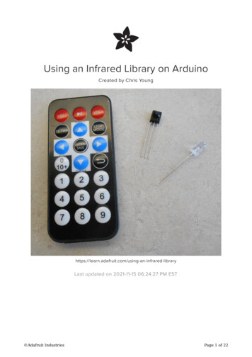
You will need an IR receiver. Such as the TSOP38238 shown on the right columnunder featured products. This device combines an IR sensitive photocell, a 38 kHzbandpass filter, and automatic gain control. It operates on a variety of supply voltagesincluding 3.3v and 5v. It de-modulates the received IR signal and gives you a niceclean square wave of off and on pulses at the voltage level of your power supply. Thismeans it is ideal for feeding its output directly into the digital input pin of our Arduino.Finally you will need an IR remote such as you use for controlling your TV, cable box,or DVD player. All of our examples will use the Adafruit Mini Remote Control shown onthe right however we will show you how to detect what protocol your own TV remoteis using and if it is a protocol supported by IRLib you can use it instead.Connecting the IR receiver is very simple. Connect the left-hand pin to any digitalinput pin on your Arduino. In our examples we will use pin 2. Connect the center pinto ground and the right-hand pin to 5v.Note that this device has a bandpass filter tuned to 38 kHz which is the typicalfrequency for most protocols. However some protocols use frequencies from 36 kHzall the way up to 57 kHz. The filter however is not extremely specific and we have hadgood success receiving anywhere from 36-40 kHz using a 38 kHz receiver. ThePanasonic Old protocol however uses 56 kHz. The TSOP38238 sold by Adafruit hasdifficulty decoding that frequency. I have however had good success with the receiver Adafruit IndustriesPage 6 of 22
sold by Radio Shack at 56 kHz even though it is a 38 kHz device. Radio Shock did notlist a part number but we believe it to be a TSOP4438. Sadly that may not be anoption anymore :-(These devices are made by Vishay and come in a variety of package styles,frequencies, and AGC methods. If the Adafruit device does not work for you and youneed 56 kHz you can refer to the following guide.IR Receiver Selection Guide fromVishay (PDF format)https://adafru.it/ezbMore information on receivers as well as schematics for using multiple receivers canbe found in the IRLib manual section 1.4.3.Decoding IR DataLoad the following sketch. It is a slightly modified version of "dump" sketch from theexamples folder of the library. All of the example sketches are in the folder "IRLib2/examples".#include "IRLibAll.h"//Create a receiver object to listen on pin 2IRrecvPCI myReceiver(2);//Create a decoder objectIRdecode myDecoder;void setup() {Serial.begin(9600);delay(2000); while (!Serial); //delay for LeonardomyReceiver.enableIRIn(); // Start the receiverSerial.println(F("Ready to receive IR signals"));}void loop() {//Continue looping until you get a complete signal receivedif (myReceiver.getResults()) {myDecoder.decode();//Decode itmyDecoder.dumpResults(true); //Now print results. Use false for less detailmyReceiver.enableIRIn();//Restart receiver}}After the sketch has loaded, open your serial monitor and make sure it is set to 9600baud. Aim your IR remote at the receiver and press a button. In this example we pressthe "Play/Pause" button on the Adafruit Mini Remote. The results were as follows: Adafruit IndustriesPage 7 of 22
Decoded NEC(1): Value:FD807F (32 bits)Raw samples(68): Gap:40826Head: m8850 s44500:m500 s600 1:m550 s550 2:m500 s600 3:m550 s6004:m500 s600 5:m500 s600 6:m500 s600 7:m550 s5508:m500 s1750 9:m500 s1700 10:m500 s1700 11:m550 s165012:m550 s1700 13:m500 s1700 14:m500 s600 15:m550 s170016:m500 s1700 17:m500 s600 18:m500 s600 19:m500 s60020:m550 s600 21:m450 s650 22:m500 s600 23:m500 s60024:m500 s600 25:m500 s1700 26:m550 s1700 27:m500 s170028:m500 s1700 29:m550 s1700 30:m500 s1700 31:m500 s170032:m500Extent 65850Mark min:450 max:550The important part of this dump is the first line. This tells us that the protocol detectedwas "NEC" which is protocol number "1" in IRLib's supported protocols. The data valuereceived was the 32-bit hexadecimal value FD807F. The rest of the information is theraw timing data of the actual marks and spaces received. That information is useful intrying to understand and supported protocols.This 32-bit number uniquely identifies the button that you pushed. If we push theVolume down and Volume up buttons on this remote we would get thevalues 0xFD00FF and 0xFD40BF.Try pressing various buttons on a TV or DVD remote you might have lying around thehouse. If the top line says:Decoded Unknown(0): Value:0 (0 bits)this means that IRLib did not understand the protocol used by your remote. Here aresome typical values from other remotes. I got these from the power button on a SonyDVD player, and the play button on my Scientific Atlantic DVR/Cable Box.Decoded Sony(2): Value:74BCA (20 bits)Decoded Panasonic Old(5): Value:37990C (22 bits) Adafruit IndustriesPage 8 of 22
This shows that the DVD player used Sony protocol which is protocol number 2 andthat it is a 20 bit protocol. The cable box uses Panasonic Old protocol 5 which is 22bits. Most protocols always use the same number of bits however some such as Sonyhave different versions which could use 8, 12, or 15 bits in addition to 20.How It WorksLet's look at what's going on here. The receiver object listens to the IR sensor andwhen it sees a signal it starts measuring the timing of the marks and spaces. If aparticular amount of time passes with no additional signals, it presumes that the datais complete and when you call My Receiver.GetResults it returns "true". It passes thedata to your decoder object. The decoder uses the timing information and the numberof bits to see if it matches one of the supported protocols. If it succeeds, it returns"true" although in this sketch we did not bother to check that first.You can access the protocol number in My Decoder.protocolNum, the number of bitsin My Decoder.bits and the the decoded data value in My Decoder.value.At the top of the sketch we created the decoder object as type "IRdecode". This is aclass which incorporates all 11 of the supported protocols. If you're using the library tocontrol a device such as a servo or turn relays off and on, you probably are going tobe using one remote with one protocol. Once you know which protocol you are using,you may wish to use a different decoder class that only works for your particularprotocol. It can save valuable program space in your sketch. For example if we wereusing the Adafruit Mini Remote which uses NEC protocol would change line #7 toread:IRdecodeNEC My Decoder;Protocol Specific IssuesIRLib supports 11 protocols directly and may include example code on how toimplement others. As stated earlier, one of the jobs of a library is to isolate theapplication programmer from the need to deal with internal issues. However there aresome protocol specific things that you may need to deal with.The protocols are enumerated in IRLibProtocols/IRLibProtocols.h at approximately line14 as follows. Adafruit IndustriesPage 9 of 22
define#define#define#define#defineUNKNOWN 0NEC 1SONY 2RC5 3RC6 4PANASONIC OLD 5JVC 6NECX 7SAMSUNG36 8GICABLE 9DIRECTV 10RCMM 11Here are some protocol specific issues you may have to deal with.NEC Repeat CodesThe NEC protocol uses a special sequence of marks and spaces that mean "I helddown the button so you should repeat whatever I sent you last time". It is up to you todecide do I want to allow repeat codes or do I want to force the operator to push andrelease the button each time. IRLib returns a value of 0xFFFFFFFF to tell you that thespecial repeat sequence was received. You can ignore that sequence which forcesthe user to release and repress the button each time or you can store the previouslyreceived code and process it whenever you see the special repeat message.Sony Triple MessagesThe technical specification for Sony protocol says that you should send each code 3consecutive times per keypress. IRLib takes care of sending three times for you soyou don't need to do anything special. However when receiving Sony, be aware thatyou're going to get three copies of the data each time the user presses a button. Ifyou're busy processing the first sequence you might miss the other two so it won'tmatter. But you need to be aware of it in case you're counting the number ofkeypresses or some other application.RC5 and RC6 Toggle BitsThe RC5 and RC6 protocols invented by Phillips use a special toggle bit to let youknow whether a code was generated by holding down the button or whether this isan independent keypress. For example I have a TV which uses RC5 protocol and thecode for Volume Up is 0x1010. If I press and hold that button it sends the same coderepeatedly. However if I release the button and press it again I get 0x1810. Everyother keypress the single bit 0x0800 will toggle off and on. You can make sure that Adafruit IndustriesPage 10 of 22
you ignore this feature by masking out that particular bit. When you receive adecoded value from this protocol you could do:My Decoder.value & 0xf7ff;This will make sure that the toggle bit is always off. The RC6 protocol also has a titlebit which is 0x10000. Therefore to mask it out you would do:My Decoder.value & 0xfeffff;Controlling NeoPixels with IRIn this very simple example we will change the color of a NeoPixel by pushing buttonson the remote. We are using a single pixel but you can modify the sketch to control anentire strip or matrix. For more information on NeoPixels visit this guide in the AdafruitLearning System (https://adafru.it/dhw). Here is the code:#include <Adafruit NeoPixel.h>#include <IRLibAll.h>IRrecv myReceiver(2);//receiver on pin 2IRdecode myDecoder;//Decoder object//One NeoPixel connected to pin 6Adafruit NeoPixel strip Adafruit NeoPixel(1,6,NEO GRB NEO KHZ800);void setup() {strip.begin();strip.show(); // Initialize all pixels to 'off'myReceiver.enableIRIn(); // Start the receiver} Adafruit IndustriesPage 11 of 22
void loop() {if (myReceiver.getResults()) {myDecoder.decode();if (myDecoder.protocolNum NEC) {switch(myDecoder.value) {case 0xfd00ff: //Volume Downstrip.setPixelColor(0,255,0,0);//Redbreak;case 0xfd807f: break;case 0xfd40bf: //Volume p.show();myReceiver.enableIRIn(); //Restart the receiver}}}We create a NeoPixel strip with one pixel connected to pin 6. Also create a receiverobject connected to pin 11 and a decoder object. Reinitialize the pixel strip and the IRreceiver in the setup routine. Then in the main loop continuously test the receiver tosee if it has received many IR signals. If myReceiver.getResults returns true then wedecode the data. We are using the Adafruit Mini Remote we used earlier. It used theNEC protocol so we make sure that we actually received NEC protocol data. Then weuse a switch statement to test various 32-bit hex values against the decoded data inMy Decoder.value.After we have set the pixel color based on the received value, we need to callstrip.show() to actually change the color and myReceiver.enableIRIn() to reset thereceiver so it can collect another code.Upload the sketch and try pressing the volume down, play/pause, and volume upbuttons. You should see the pixel change to red, green, or blue. You can easily addadditional case statements and colors or perhaps have one of the cases call ananimation routine to animate the entire strip of pixels. Different buttons on the remotewould select different animation patterns.You will have to modify this sketch if you are using a different remote control. Changethe protocol type spuch as:if (myDecoder.protocolNum SONY)for example if you are using a Sony remote. And of course you have to substitute theproper codes in each case statement. The enumerated list of available protocols forcomparing decode type can be found at approximately line 60 of IRLib.h. Adafruit IndustriesPage 12 of 22
Controlling a Servo with IRSetting up the ExampleIn this example we will control the servo using an IR remote. We can adjust the speedthat the servo moves and we can select individual preset angles for positioning theservo.Here is an illustration showing how to wire up the devices. As usual we have an IRreceiver connected to 5v, ground, and pin 11. We also have a servo with three wires.The red wire is 5v. The black or dark brown wire is ground and the remaining wireusually yellow is the signal wire which we have connected to pin 9 although it couldbe any digital output pin. Adafruit IndustriesPage 13 of 22
NOTE: The above illustration shows the receiver on pin 11 however the samplecode uses pin 2. Any digital input pin can be used.Upload the CodeBelow is a version of the servo.ino sketch from the "IRLib2/examples" folder. It hasbeen modified to be used with the Adafruit Mini Remote. If you're using a differentremote, you will have to collect information about your codes for various buttonsusing dump.ino and modify the sketch with the proper protocol name and codes.#include <IRLibAll.h>#include <Servo.h>// You will have to set these values depending on the protocol// and remote codes that you are using. These are For the Adafruit// Mini Remote#define MY PROTOCOL NEC#define RIGHT ARROW0xfd50af //Move several clockwise#define LEFT ARROW0xfd10ef //Move servo counterclockwise#define SELECT BUTTON 0xfd906f //Center the servo#define UP ARROW0xfda05f //Increased number of degrees servo moves#define DOWN ARROW0xfdb04f //Decrease number of degrees servo moves#define BUTTON 0 0xfd30cf //Pushing buttons 0-9 moves to fixed positions#define BUTTON 1 0xfd08f7 // each 20 degrees greater#define BUTTON 2 0xfd8877#define BUTTON 3 0xfd48b7#define BUTTON 4 0xfd28d7#define BUTTON 5 0xfda857 Adafruit IndustriesPage 14 of 22
#define#define#define#defineBUTTON 6BUTTON 7BUTTON 8BUTTON 90xfd68970xfd18e70xfd98670xfd58a7IRrecv myReceiver(2); //pin number for the receiverIRdecode myDecoder;Servo myServo; // create servo object to control a servoint16 t pos;// variable to store the servo positionint16 t Speed;// Number of degrees to move each time a left/right button ispresseduint32 t Previous;//handles NEC repeat codesvoid setup() {myServo.attach(9);// attaches the servo on pin 9 to the servo objectpos 90;// start at midpoint 90 degreesSpeed 3;// servo moves 3 degrees each time left/right is pushedmyServo.write(pos);// Set initial positionmyReceiver.enableIRIn(); // Start the receiver}void loop(){if (myReceiver.getResults()) {myDecoder.decode();if(myDecoder.protocolNum MY PROTOCOL) {if(myDecoder.value 0xFFFFFFFF)myDecoder.value Previous;switch(myDecoder.value) {case LEFT ARROW:pos min(180,pos Speed); break;case RIGHT ARROW:pos max(0,pos-Speed); break;case SELECT BUTTON: pos 90; break;case UP ARROW:Speed min(10, Speed 1); break;case DOWN ARROW:Speed max(1, Speed-1); break;case BUTTON 0:pos 0*20; break;case BUTTON 1:pos 1*20; break;case BUTTON 2:pos 2*20; break;case BUTTON 3:pos 3*20; break;case BUTTON 4:pos 4*20; break;case BUTTON 5:pos 5*20; break;case BUTTON 6:pos 6*20; break;case BUTTON 7:pos 7*20; break;case BUTTON 8:pos 8*20; break;case BUTTON 9:pos 9*20; break;}myServo.write(pos); // tell servo to go to position in variable 'pos'Previous myDecoder.value;}myReceiver.enableIRIn();}}NOTE: If using Leonardo, Micro, or Yun or other ATmega32u4 System, See thespecial instructions at the end of this page.Upload the sketch and try pushing the left and right arrow buttons. The servo shouldturn left and right. Pushing the enter button should center the servo. Pushing the upor down arrow buttons will not have any visible effect but it will change the speed ofmovement you push left or right. The numbered buttons from zero through nine movethe servo to 10 different fixed positions at 20 intervals. Adafruit IndustriesPage 15 of 22
If the servo behaves erratically, it may be a power supply problem. Some USB portsdo not deliver sufficient current to drive the Arduino and move the servo. You mayneed to add an external 5 volt supply. Here is a video demonstrating this example.How It WorksThe program creates a receiver on object, a decoder object and a servo object. Youcan find more information on the standard Arduino Servo library here (https://adafru.it/ecQ). The setup function attaches the servo, enables IR input, and initializes severalvariables.The loop function gets an IR code and passes it to a switch statement depending onits value. Each case of the switch statement handles a different function moving theservo as needed.There is one bit of overhead we need to take care of because we are using NECprotocol. That protocol has a unique feature that allows you to see if the button onthe remote has been held down to send repeated instances of the same value. It hasa special sequence of marks and spaces that mean "Repeat what you did last time".When IRLib sees the special sequence, it returns the value 0xFFFFFFFF. We take careof that special case by storing the previous value at the bottom of the switchstatement so that if we get a repeat code we can substitute it the next time. NECprotocol is the only protocol that uses this particular method for detecting repeatcodes. Other protocols have other systems which are explained in detail in the IRLibdocumentation.Special Instructions for ATmega32u4 basedsystemsThe example as presented here should work okay on Arduino Uno or Mega howeverif you are using Arduino Leonardo, Arduino Micro, Arduino Yun or other ATmega32u4based systems, you will have to make a slight modification to IRLib.IRLib uses your Arduino's built in hardware timers to generate an interrupt every 50µsso it can poll the input pin to see if it has changed. By default it uses TIMER2. TheArduino servo library also uses hardware interrupts using TIMER1. However theATmega32u4 processor does not have TIMER2 so IRLib defaults to TIMER1 onsystems using that processor. You will have to modify "IRLibProtocols/ Adafruit IndustriesPage 16 of 22
IRLibHardware.h" to change the default timer. In that file at approximately line 56 youwill see something like this:#elif defined( AVR ATmega32U4 )#ifdef CORE TEENSY// it's Teensy 2.0//#define IR SEND TIMER114//#define IR SEND TIMER39#define IR SEND TIMER4 HS#else/* it's probably Leonardo */#define IR SEND TIMER1//#define IR SEND TIMER35//#define IR SEND TIMER4 HS#endif10913You will need to put // in front of #define IR SEND TIMER1 to comment out that line.Then remove the slashes from in front of one of the other two options either TIMER3or TIMER4 HS. Note that these defines say "IR SEND TIMERxx". Later in the file wecopy this value to also be used as the receiving timer. If you're using Leonardo andyou later use IRLib to send IR signals you will need to make note of the numbers afterthese defines. Although we can hook a receiver to any digital input pin, IRLib requiresyou to use specific output pins depending on which timer you are using. Will coverthat later in the section on sending. Adafruit IndustriesPage 17 of 22
Sending IR CodesHardware IssuesIRLib not only receives and decodes IR signals but it can transmit them as well usingan IR LED and a driver circuit. The library has been used to control TVs, cable boxes,DVDs, VCRs, and IR controlled toys such as helicopters and dinosaur robots.It could also be used to control some home automation devices. Some users haveattempted to control air conditioners and fans however protocols used for airconditioners are extremely difficult to implement and we have not directly supportedsuch protocols because they are very rare.Typically the output pin of an Arduino cannot supply sufficient current to drive and IRLED so you will want to implement a simple driver circuit using NPN transistor and a470 ohm resistor is shown here: Adafruit IndustriesPage 18 of 22
Make sure that you get the polarity of the LED correct. The shorter of the two leadsconnects to the transistor and the longer one connects to the positive supply. Notethat the current passing through the LED will in all likelihood will exceed the maximumcontinuous current rating. However because the signal is modulated and sending asequence of pulses that will only last a few milliseconds the circuit will work fine.More advanced driver circuit schematics are available in the IRLib manual in section1.4 Hardware Considerations.While we can connect an IR receiver to any available digital input pin, you can onlyuse very specific pins for output. The library uses PWM pins and modifies the timingparameters to change the default frequency of that pin.The default timer is TIMER2 on the Arduino Uno and Arduino Mega. On the Leonardowith is TIMER1. The pin numbers are pin 3 for Uno and use pin 9 for the Leonardo andMega. If you have modified the library to use a different timer such as changing thetimer number on a Leonardo to avoid conflicts with the servo library, then you willneed to use a different specific pin. See section 1.4.1 Supported Platforms in the IRLibusers manual for a table which shows the relationship between hardware timers andpin numbers. Adafruit IndustriesPage 19 of 22
Loading the SoftwareWe presume you have already installed the IRLib library as described earlier in thistutorial. Let's load a simple sketch and see how it works. This is the IRsendDemosketch from the examples folder.#include <IRLibAll.h>IRsend mySender;void setup() {Serial.begin(9600);}void loop() {if (Serial.read() ! -1) {//send a code every time a character is received from the serial port//Sony DVD power A8BCAmySender.send(SONY,0xa8bca, 20);}}In this somewhat trivial example we send the code to turn on and off a Sony DVDplayer every time you type a character into the serial monitor. We create a sendingobject mySender. There is no set up except to initialize the serial port. In the loop wecheck for incoming characters and if we've got one we send the code.The send method has three parameters: the protocol type, the data, and the numberof bits.The IRsend object we created is a generic routine that supports all 11 supportedprotocols. However in this case since we are only using one protocol we could'vecreated the object using:IRsendSony mySender;Inside the loop the send command would then be:mySender.send(0xa8bca, 20);Some protocols such as NEC always use the same number of bits and so you do notneed to specify as an additional parameter. See the the users manual to see if theextra bits parameter is required. Adafruit IndustriesPage 20 of 22
The users manual also gives you information about how to create decoding andsending routines that only use a specific subset of the supported protocols. This ismuch easier to do in IRLib 2.0 than it was in the original version.Sending and Receiving in the SameProgramThere are special considerations when doing sendi
Nov 15, 2021 · Libraries should not be installed alongside the Arduino application itself. Re-start the Arduino IDE if it’s currently running This repository consists of a total of five libraries each of which must be in your arduino/libraries/ folder. So for example it should be installed as follows arduino/libr