Transcription
Controller Area Network Prototyping with Arduinoby Wilfried VossPublished byCopperhill Technologies Corporation158 Log Plain RoadGreenfield, MA 01301USACopyright 2014 by Copperhill Technologies CorporationCover Design by Copperhill Technologies CorporationNo part of this publication may be reproduced, stored in a retrieval system or transmitted in any form or by any means,electronic, mechanical, photocopying, recording, scanning or otherwise, except as permitted under Sections 107 or 108of the 1976 United States Copyright Act, without the prior written permission of the Publisher.All trademarks or copyrights mentioned herein are the possession of their respective owners and Copperhill Mediamakes no claim of ownership by the mention of products that contain these marks.“Arduino” is a trademark of the Arduino team.ISBN-10: 1938581172ISBN-13: 978-1-938581-17-5Disclaimer: While the publisher and author have used their best efforts in preparing this book, they make norepresentations or warranties with respect to the accuracy or completeness of the contents of this book and specificallydisclaim any implied warranties or merchantability or fitness for a particular purpose. No warranty may be created orextended by sales representatives or written sales materials. The advice and strategies contained herein may not besuitable for your situation. You should consult with a professional where appropriate. Neither the publisher nor authorshall be liable for any loss or profit or any other commercial damages, including but not limited to special, incidental,consequential, or other damages.http://www.copperhilltech.com
From the AuthorIt seems like a million years since I had a soldering iron in my hand and that I have beenengaging in my most favorite programming activity, namely programming of embeddedsystems. In the past, I did shy away from the expenses that came with embeddedprogramming, but with the emergence of inexpensive prototyping systems such as theArduino or Raspberry Pi this concern doesn’t exist anymore.Add to this a virtually non-existing learning curve. With my Arduino Uno I ordered abook explaining Arduino Sketches, and I read it for about 30 minutes to scan through themost important information. Then it took maybe another 30 minutes to get my firstapplication running.I know, I am joining the enormous club of Arduino users who made and expressed thesame experience, but that doesn’t change the fact that the Arduino is the perfectenvironment for prototyping of embedded computer systems.Naturally, with my knowledge of all kinds of Controller Area Network topics, I was eagerto convert that knowledge into the real thing, namely a working CAN application. ThatCAN application will be the basics of an USB-to-CAN Gateway with CAN networkmonitoring and diagnostic features as explained in the chapters to follow. From here on,with the knowledge gained through this project, I encourage you to let your mind flow andextend the application. The possibilities are plenty. Enjoy!However, before we get there let me explain the approach of writing this book: I couldhave engaged into writing many pages about Arduino basics, what it is, where it comesfrom, how to use it, etc., for the mere purpose of adding more pages and, as a result, beingable to charge more money for my book. However, there are myriads of books onArduino, Arduino Sketches, and Arduino Shields available in the market, and I won’twaste your money or time. However, references to Arduino basics may appear but only inpassing.That being said, this book assumes some knowledge of the Arduino hardware and itsprogramming.It also assumes some basic knowledge of Controller Area Network (CAN). I will refer
briefly to some aspects of CAN, but these are the mere basics of the actual protocol, justenough to understand the concept. In all truth, there is no need to understand all details ofthe protocol, since 100% of the protocol is implemented on a chip, the CAN controller. Allwe need to do in this book is to receive, transmit, and process data. The rest is up to yourfantasy.Nevertheless, the CAN protocol utilizes some ingenious features, and if you are interestedin learning more, please refer to A Comprehensible Guide to Controller Area Network asmentioned in the literature appendix of this book.Last, but not least, let me lose some words on my programming style that is definitelydifferent than what you usually see.I put great emphasis not only on readability of code; I also have debugging in mind when Iwrite code. I am using a slightly modified version of the Hungarian Notation, meaninglooking at a variable’s or function’s name provides you some information about its nature.For instance, the prefix n indicates an integer variable (e.g. nVariable). In addition, beingfamiliar with a number of programming languages, I attempt to keep the best of all worlds.For instance, I add comments behind almost every bracket to indicate information such asend if or end while, etc., which helps identify program blocks. This may be helpful forVisual Basic programmers who are new to C/C programming.Like under Visual Basic, my functions/routines start with either Sub (the return code isvoid) or xFct (where x indicates the type of the return code, for instance, n for integer).About the AuthorI am the author of the “Comprehensible Guide” series of technical literature coveringtopics like Controller Area Network (CAN), SAE J1939, Industrial Ethernet, and ServoMotor Sizing. I have worked in the CAN industry since 1997 and before that was a motioncontrol engineer in the paper manufacturing industry. I have a master’s degree inelectrical engineering from the University of Wuppertal in Germany.During the past years, I have conducted numerous seminars on industrial fieldbus systemssuch as CAN, CANopen, SAE J1939, Industrial Ethernet, and more during various RealTime Embedded And Computing Conferences (RTECC), ISA (Instrumentation, Systems,and Automation Society) conferences and various other events all over the United Statesand Canada.
I had the opportunity of traveling the world extensively, but settled in New England in1989. I presently live in an old farmhouse in Greenfield, Massachusetts with my redhaired, green-eyed Irish-American wife and our son Patrick.For more information on my works and to contact me, see my website athttp://copperhilltech.com.Contact the AuthorDespite all efforts in preparing this book, there is always the possibility that some aspectsor facts will not find everybody’s approval, which prompts us, author and publisher, to askfor your feedback. If you would like to propose any amendments or corrections, pleasesend us your comment. We look forward to any support in supplementing this book, andwe welcome all discussions that contribute to making the topic of this book as thoroughand objective as possible.To submit amendments and corrections please log on to the author’s website athttp://copperhilltech.com/contact-us/ and leave a note.Code And Projects DownloadAny additional information created after the publishing date of this book plus project &source code (Arduino and Windows) are available as a free download through the oller-area-network-can-prototyping-witharduino/
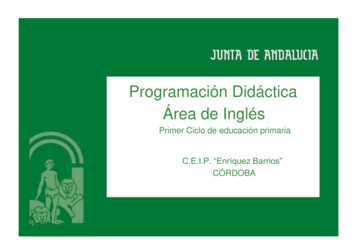
1. Introduction to Controller Area NetworkController Area Network (CAN) is a serial network technology that was originallydesigned for the automotive industry, especially for European cars, but has also become apopular bus in industrial automation as well as other applications. The CAN bus isprimarily used in embedded systems, and as its name implies, is a network technology thatprovides fast communication among microcontrollers up to real-time requirements,eliminating the need for the much more expensive and complex technology of a DualPorted RAM.CAN is a two-wire, half duplex, high-speed network system, that is far superior toconventional serial technologies such as RS232 in regards to functionality and reliabilityand yet CAN implementations are more cost effective.While, for instance, TCP/IP is designed for the transport of large data amounts, CAN isdesigned for real-time requirements and with its 1 MBit/sec baud rate can easily beat a100 MBit/sec TCP/IP connection when it comes to short reaction times, timely errordetection, quick error recovery and error repair.CAN networks can be used as an embedded communication system for microcontrollersas well as an open communication system for intelligent devices. Some users, for examplein the field of medical engineering, opted for CAN because they have to meet particularlystringent safety requirements.Similar requirements had to be considered by manufacturers of other equipment with veryhigh safety or reliability requirements (e.g. robots, lifts and transportation systems).The greatest advantage of Controller Area Network lies in the reduced amount of wiringcombined with an ingenious prevention of message collision (meaning no data will be lostduring message transmission).
Without CANWith CANThe following shows a need-to-know overview of CAN’s technical characteristics.Controller Area NetworkIs a serial networking technology for embedded solutions.Needs only two wires named CAN H and CAN L.Operates at data rates of up to 1 Megabit per second.Supports a maximum of 8 bytes per message frame.Does not support node IDs, only message IDs. One application can supportmultiple message IDs.Supports message priority, i.e. the lower the message ID the higher its priority.Supports two message ID lengths, 11-bit (standard) and 29-bit (extended).Does not experience message collisions (as they can occur under other serialtechnologies).Is not demanding in terms of cable requirements. Twisted-pair wiring is sufficient.Note: For more detailed information on CAN, please refer to “A Comprehensible Guide toController Area Network” as mentioned in the literature appendix of this book.
2. Prototyping Hardware and its VariantsAs I had mentioned earlier in this book, it is assumed that you have some basic knowledgeof the Arduino, Arduino Sketches, and Arduino Shields. I will nevertheless take theopportunity of mentioning the prototyping hardware and its variants.It is important to know that the Arduino, even though perfect for prototyping due to itslow price and ease of programming, is not, in its bare form, an industrial-strength solution,not only in terms of environmental specs (e.g. temperature range, etc.) but also in terms ofexecution speed and memory resources.Specifically, when it comes to CAN applications at 1 Mbit/sec and high data traffic, theArduino may reach its limits quickly. There are, however, advanced and yet compatiblealternatives to the Arduino as explained in the following chapters.
2.1 ArduinoIn order to develop and test the sample programs (sketches) as shown in this book, I usedthe Arduino Uno. The hardware consists of an open-source hardware board, usuallydesigned around an 8-bit Atmel AVR microcontroller with 2 KB RAM (workingmemory), 32 KB Flash Memory (sketches) and 1 KB EEPROM (non-volatile).These technical specifications are more than sufficient for basic prototyping of CANapplications and the proof of concept. However, to re-iterate the point, with growingdemands for execution speed and extended functionality, the Arduino may quickly reachits limits.Note: All Arduino programs (sketches) as shown in this book were developed and testedwith the Arduino Uno. There is no guarantee that these programs will work “as is” on anyother compatible system.
2.2 Intel GalileoThe Intel Galileo is a microcontroller board based on the Intel Quark SoC X1000Application Processor, a 32-bit Intel Pentium-class system on a chip. It is designed to behardware and software pin-compatible with Arduino shields designed for the Uno R3.The Galileo board is also software compatible with the Arduino software developmentenvironment, which should make usability and introduction a snap.In addition to Arduino hardware and software compatibility, the Galileo board has severalPC industry standard I/O ports and features to expand native usage and capabilitiesbeyond the Arduino shield ecosystem. A full sized mini-PCI Express slot, 100Mb Ethernetport, Micro-SD slot, RS-232 serial port, USB Host port, USB Client port, and 8MByteNOR flash come standard on the board.The CPU is a 400MHz 32-bit Intel Pentium instruction set architecture (ISA)-compatibleprocessor, and there is up to 8 MByte of Flash available. (Source: Galileo Datasheet rk-board.html
2.3 LeafLabs Maple Microcontroller BoardAs similar as it may be to the Arduino, the differences are what really make the Maplestand out. It harnesses the power of a 32-bit ARM Cortex-M3 clocked at 72 MHz to push39 GPIOs, 16 analog pins, 12-bit ADC resolution and 15 PWM pins at 16-bit resolution.In order to make sure you have plenty of programming room to flex that hardware, theMaple also provides 128k Flash and 20KB SRAM. All of this performance is delivered inthe same form factor as the Arduino Pro.If your current Arduino-based project is pushing against the performance limits of theATmega, porting it over to Maple may be the fastest and easiest way to continuedeveloping your project without starting from scratch.By swapping the popular “avr-gcc” compiler with CodeSourcery’s “arm-none-eabi-gcc,”LeafLabs manages to provide a nearly identical programming experience to Arduinodespite targeting a completely different architecture. Also, while some Arduino shields areincompatible due to certain capabilities being allocated to different pins, several of themare currently supported and there are more to come. There is also a guide available on theproduct page for porting Arduino libraries and source code over to Maple. (Source:LeafLabs open electronis)For more information see: http://leaflabs.com/docs/hardware/maple.html
3. Arduino CAN ShieldsSince Controller Area Network (CAN) is predominantly targeted at industrial solutions(versus the vastly more popular USB for non-industrial use such as home and lab), therearen’t too many choices available in the market.Through some research (i.e. browsing) I found two very similar solutions, and they bothwork with the same CAN library (as explained in a later chapter). Both solutions use theMicrochip MCP2515 CAN controller. Also, both solutions are distributed throughworldwide online resources.
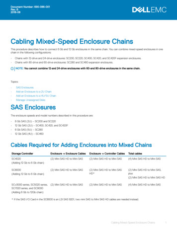
3.1 Microchip MCP2515 CAN ControllerMicrochip Technology’s MCP2515 is a stand-alone Controller Area Network (CAN)controller that implements the CAN specification, version 2.0B. It is capable oftransmitting and receiving both standard and extended data and remote frames. TheMCP2515 has two acceptance masks and six acceptance filters that are used to filter outunwanted messages, thereby reducing the host MCUs overhead. The MCP2515 interfaceswith microcontrollers (MCUs) via an industry standard Serial Peripheral Interface (SPI).The features include two receive buffers with prioritized message storage, six 29-bitfilters, two 29-bit masks, and three transmit buffers with prioritization and abort features.(Source: Microchip Datasheet)Note: CAN specification 2.0B refers to the capability of using standard CAN frames with11-bit message identifier plus the extended format with a 29-bit message ID.To download the full MCP2515 datasheet log on /21801G.pdfBoth CAN shields as described in the following chapters utilize the Microchip MCP2551CAN transceiver, which converts the internal TTL signals to a differential voltage asdemanded by the CAN standard.To download the full MCP2551 datasheet log on /21667f.pdf
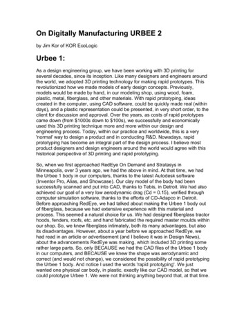
3.2 Arduino CAN-Bus Shield by SK Pang electronicsThis shield by SK Pang electronics provides the Arduino CAN-Bus capability. Asexplained previously, it uses the Microchip MCP2515 CAN controller with MCP2551CAN transceiver. The CAN connection is realized via a standard 9-way sub-D, howeverthe pin assignment for CAN H, CAN L is not according to standard.Note: In all truth, there is no mandatory standard for pin assignment, but the industry usespins 2 (CAN L) and 7 (CAN H) as a virtual standard.I recommend using the on-board CAN L and CAN H contacts to solder the CAN cabledirectly to the board.The shield also comes with a uSD card holder, a serial LCD connector, and a connector foran EM406 GPS module, making this shield suitable for data logging application.FeaturesCAN v2.0B up to 1 Mb/sHigh speed SPI Interface (10 MHz)Standard and extened data and remote framesCAN connection via standard 9-pin sub-D connectorAs an option, power can be supplied to the Arduino by sub-D via resettable fuseand reverse polarity protection.Socket for EM406 GPS moduleMicro SD card holderConnector for serial LCDReset buttonJoystick control menu navigation controlTwo LED indicator
NotesNo cables includedHeader pins are not included; they must be ordered separatelyPin assignment for CAN H, CAN L not according to standardAll technical information regarding the use of the CAN controller, uSD card holder,joystick, LEDs, etc. can be found on the company’s wiki website at:https://code.google.com/p/skpang/Ordering InformationTo order the SK Pang ele3ctronics CAN shield, you can use the following resources (orbrowse for “Arduino CAN-BUS Shield” for further options):Sparkfun - https://www.sparkfun.com/products/10039SK Pang electronics - with-usd-cardholder-p-706.html
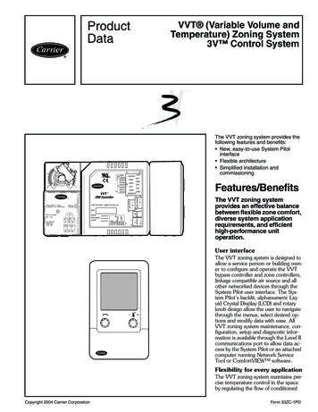
3.3 CAN-BUS Shield by Seeed StudioIn terms of CAN capabilities, the shield by Seeek Studio provides the same functionalityas the one by SK Pang electronics, however, it comes with a much lower price tag,because it does not have any additional components besides the CAN interface.Over all, the device makes a solid impression, especially since the CAN connection isaccording to standard and in addition provides CAN connectivity through easily accessibleterminals.FeaturesImplements CAN V2.0B at up to 1 Mb/sSPI Interface up to 10 MHzStandard (11 bit) and extended (29 bit) data and remote framesTwo receive buffers with prioritized message storageIndustrial standard 9 pin sub-D connectorTwo LED indicatorsNotesNo cables includedAll technical information regarding the use of the CAN controller can be found on thecompany’s wiki website at:http://www.seeedstudio.com/wiki/CAN-BUS Shield
Ordering InformationTo order the Seeed Studio CAN shield, you can use the following resources (or browse for“Arduino CAN-BUS Shield” for further options):Seeed Studio - 256.htmlImportant to know: The Seeed Studio CAN bus shield has been undergoing somehardware changes to become compatible with systems such as the Arduino Mega 2560.The version 1.0 will work with the Arduino Uno, while all higher versions also work withthe Mega 2560. This will also affect the code of the Arduino projects, specifically the line“MCP CAN CAN0(10);” in the main module selecting the CS pin. That line must changeto “MCP CAN CAN0(9);” for all CAN bus shield versions above 1.0. I have added acomment in the corresponding section of the code.
4. Arduino CAN SketchesThe implementation of either one of the introduced CAN-BUS Shields and thecorresponding CAN sketches went surprisingly smooth when paired with the right librarysoftware.I found several source codes for accessing the MCP2515 CAN controller, but most ofthem didn’t even pass the initial quality control phase (I read the code first before I use it).One of the quality criteria was the support for 29-bit CAN message identifiers (CAN 2.0BCompatibility), which is mandatory when it comes to implementing, for instance, the SAEJ1939 vehicle network protocol. Some software samples I found were just literally“samples” and they left ample room for guessing games.I was most pleased by the MCP2515 Library by Cory Fowler, which can be found athttps://github.com/coryjfowler/MCP2515 libThis library is compatible with any shield or CAN interface that uses the MCP2515 CANprotocol controller.In order to test and verify the proper transmission and reception of CAN messages, I usedthe ADFweb CAN-to-USB gateway with its Windows interface.Note: In order to test a CAN application, you need at least two CAN nodes to establish anetwork communication. The second node can be another Arduino with CAN shield or (ifthe budget allows) another CAN device with CAN data monitoring capabilities.
4.1 The MCP2515 LibraryAs with any serial networking controller, the essential functions are:1. Initialization2. Read Data3. Write Data4. Check StatusIn case of the MCP2515 library, these functions are represented by:1. Initialization: CAN0.begin2. Read Data: CAN0.readMsgBufincl. CAN0.checkReceive, CAN0.getCanId3. Write Data: CAN0.sendMsgBuf4. Check Status: CAN0.checkError4.1.1 Function CallsFunction:Purpose:Parameter:Return Code:CAN0.beginInitializes the CAN controller and sets the speed (baud rate)CAN 5KPS CAN 1000KPS (See mcp can dfs.h)CAN OK Initialization okayCAN FAILINIT Initialization failedFunction:Purpose:CAN0.checkReceiveCheck if message was received
Parameter:Return Code:NoneCAN MSGAVAIL Message availableCAN NOMSG No ead the message buffernMsgLen returns the message length (number of data bytes)nMsgBuffer returns the actual messageReturn Code:Function:Purpose:Parameter:Return etrieves the ID of the received messageNonem nID Message IDCAN0. sendMsgBufSend a message bufferid Message IDext CAN STDID (11-bit ID) or CAN EXTID (29-bit ID)len Number of data bytes (0 8)buf Message bufferReturn Code:Function:Purpose:Parameter:Return Code:NoneCAN0.checkErrorChecks CAN controller for errorsNoneCAN OK Status okayCAN CTRLERROR ErrorThere are further functions, among others, for message filtering and settings masks, andthey are worth being checked out for more sophisticated functions, but they are notnecessary for simple CAN communication tasks.
4.1.2 ImplementationThe implementation of the MPC2515 library is fairly easy: Open Arduino, create a newfile, then use the menu items Sketch- Add File to include the following files to theproject:mcp can.cppmcp can.hmcp can dfs.hIn the Arduino project file add the following on top:#include “mcp can.h”#include SPI.h MCP CAN CAN0(10);Let me repeat here: The Seeed Studio CAN bus shield has been undergoing somehardware changes to become compatible with systems such as the Arduino Mega 2560.The version 1.0 will work with the Arduino Uno, while all higher versions also work withthe Mega 2560. This will also affect the code of the Arduino projects, specifically the line“MCP CAN CAN0(10);” in the main module selecting the CS pin. That line must changeto “MCP CAN CAN0(9);” for all CAN bus shield versions above 1.0.You are now ready to go. The following chapters will describe how to implement thefunction calls.
4.2 CAN ProgrammingThe most exciting part about this project is when it comes to the point where two CANnodes communicate with each other. I started off with writing a simple program that sentmessages that were received by my USB-to-CAN gateway and its Windows monitoringsoftware. From there on, I extended the program to also receive CAN messages anddisplay them on the Arduino serial monitor.In a later chapter, I will also show a Windows programming example that establishes acommunication with the Arduino.4.2.1 Simple CAN Shield TestThe following represents a very simple CAN test program that periodically (i.e. every 1second) sends out a CAN message with a 29-bit identifier at a baud rate of 250 kbit/sec.// Simple CAN Shield Test#include “mcp can.h”#include SPI.h MCP CAN CAN0(10); // Set CS to pin 10unsigned char stmp[8] {0x30, 0x31, 0x32, 0x33, 0x34, 0x35, 0x36, 0x37};// SYSTEM: Setup routine runs on power-up or resetvoid setup() {// Set the serial interface baud rateSerial.begin(9600);// Initialize the CAN controller// Baud rates are defined in mcp can dfs.hif (CAN0.begin(CAN 250KBPS) CAN OK)Serial.print(“CAN Init OK.\n\r\n\r”);elseSerial.print(“CAN Init Failed.\n\r”);}// end setup
// Main Loop - Arduino Entry Pointvoid loop(){// Send data: id 0x1FF, extended frame, data len 8, stmp: data buf// ID mode (11/29 bit) defined in mcp can dfs.hCAN0.sendMsgBuf(0x1FF, CAN EXTID, 8, stmp);// Run in 1 sec intervaldelay(1000);}// end loopWhile the code is short and sufficiently self-explanatory, let me explain the steps taken inthe program.In the setup() routine, the program initializes the serial interface (USB) to a baud rate of9600 bps (Please make sure that your Arduino serial monitor is set to the same rate).It then initializes the CAN controller to a data transmission rate of 250 kbits/sec anddisplays possible error messages on the Arduino serial monitor.In the main loop() routine, the program sends an 8-byte CAN message using an ID of0x1FF in extended messaging format (29-bit message ID). The actual message (unsignedchar stmp[8] in this example) contains a string from ASCII 0 to 7, which can be easilyspotted when using a data monitoring software.Using my test conditions, the message was received through the USB-to-CAN gatewayand displayed under Windows:
While this program may not be very useful without a CAN monitoring software (meaningyou can’t see the result), in the least it demonstrates how simple CAN programming canbe.4.2.2 Extended CAN Shield TestIn this next, extended example, we use the same program as shown in the previous chapterbut add a CAN receiving routine to it. The result, i.e. the received messages, will bedisplayed through the Arduino serial monitor.// Simple CAN Shield Test#include stdlib.h #include “mcp can.h”#include SPI.h MCP CAN CAN0(10);// Set CS to pin 10// Test messageunsigned char stmp[8] {0x30, 0x31, 0x32, 0x33, 0x34, 0x35, 0x36, 0x37};// SYSTEM: Setup routine runs on power-up or resetvoid setup() {// Set the serial interface baud rateSerial.begin(9600);// Initialize the CAN controller
// Baud rates defined in mcp can dfs.hif (CAN0.begin(CAN 250KBPS) CAN OK)Serial.print(“CAN Init OK.\n\r\n\r”);elseSerial.print(“CAN Init Failed.\n\r”);}// end setup// Main Loop - Arduino Entry Pointvoid loop(){// Declarationsbyte nMsgLen 0;byte nMsgBuffer[8];char sString[4];// Send out a test message// Send data: id 0x1FF, extended frame, data len 8, stmp: data buf// ID mode (11/29 bit) defined in mcp can dfs.hCAN0.sendMsgBuf(0x1FF, CAN EXTID, 8, stmp);// Check for a messageif(CAN0.checkReceive() CAN MSGAVAIL){// Read the message bufferCAN0.readMsgBuf(&nMsgLen, &nMsgBuffer[0]);INT32U nMsgID CAN0.getCanId();// Print message ID to serial monitorSerial.print(“Message ID: 0x”);if(nMsgID 16) Serial.print(“0”);Serial.print(itoa(nMsgID, sString, 16));Serial.print(“\n\r”);// Print data to serial monitorSerial.print(“Data: “);for(int nIndex 0; nIndex nMsgLen; nIndex ){
Serial.print(“0x”);if(nMsgBuffer[nIndex] 16) [nIndex], sString, 16));Serial.print(” “);}// end forSerial.print(“\n\r\n\r”);}// end if// Run in 1 sec intervaldelay(1000);}// end loopObviously, the program has grown compared to the previous one, but most of the addedcode is used for the data display on the Arduino serial monitor.First, note on top the line #include stdlib.h . The stdlib.h file allows us to convertinteger data into ASCII, which is necessary for the data display.The setup() routine remains the same as it was in the previous example.In the loop() routine, we first declare some variables for the message reception and codeconversion. We still send out the same message as before by calling theCAN0.sendMsgBuf() function.Next, we check for the reception of a CAN message, and if that is the case, we read themessage into the assigned buffer and retrieve the message ID. The following code is allabout converting the received data into a human-readable format (ASCII) and display it onthe Arduino serial monitor.Last, but not least, we halt the system for one second (1000 milliseconds). Naturally,under real-life conditions, this delay is not reasonable, since there can occur literallythousands of messages per one second. However, this code is meant merely as a demosample that proves that the actual CAN communication can be accomplished with verylittle code.If you load this program onto two separate Arduinos with CAN shield, you have not only
accomplished a full CAN network, you can also see the CAN messages as they areexchanged between the two nodes.Note: It may sound obvious, but please make sure, in case you use more than one CANnode, that all nodes are initialized with the same baud rate. Using different baud rates isthe most common cause when data communication fails.4.2.3 A Simple CAN Network Monitoring and Diagnostics ProgramThe Arduino board in combination with the CAN shield provides the hardware for a fullfledged CAN network monitoring tool, and this next Arduino program is a first step in thatdirection.However, before we get into more detail, let me issue some warnings regarding possiblerestrictions of the system:The MPC2515 has only two receive buffers, which limits the system’s capabilitiesto respond in a timely fashion while receiving and processing the data traffic. Forhigh-speed, high-busload applications, it is recommended to use the message filterfunctions to reduce the processing load on the CPU.Besides the limited processing speed of the 8-bit CPU, the Arduino comes withonly 32 kByte program memory, which is sufficient for a great number of smallapplications. However, when it comes to more demanding tasks such as a CANmonitoring tool, the memory resources may be exhausted quic
Arduino, Arduino Sketches, and Arduino Shields available in the market, and I won’t waste your money or time. However, references to Arduino basics may appear but only in passing. That being said, this book assumes some knowledge of the Arduino hardware and its programming. It also assum