Transcription
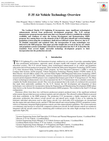
AIAA AVIATION ForumJune 25-29, 2018, Atlanta, Georgia2018 Aviation Technology, Integration, and Operations Conference10.2514/6.2018-3368F-35 Air Vehicle Technology OverviewChris Wiegand, 1 Bruce A. Bullick, 2 Jeffrey A. Catt, 3 Jeffrey W. Hamstra, 4 Greg P. Walker, 5 and Steve Wurth 6Lockheed Martin Aeronautics Company, Fort Worth, TX, 76109, United States of AmericaThe Lockheed Martin F-35 Lightning II incorporates many significant technologicalenhancements derived from predecessor development programs. The X-35 conceptdemonstrator program incorporated some that were deemed critical to establish the technicalcredibility and readiness to enter the System Development and Demonstration (SDD)program. Key among them were the elements of the F-35B short takeoff and vertical landingpropulsion system using the revolutionary shaft-driven LiftFan system. However, due to X35 schedule constraints and technical risks, the incorporation of some technologies wasdeferred to the SDD program. This paper provides insight into several of the key air vehicleand propulsion systems technologies selected for incorporation into the F-35. It describes thetransition from several highly successful technology development projects to theirincorporation into the production aircraft.I.IntroductionTHE F-35 Lightning II is a true 5th Generation trivariant, multiservice air system. It provides outstanding fighterclass aerodynamic performance, supersonic speed, all-aspect stealth with weapons, and highly integrated andnetworked avionics. The F-35 aircraft features many technological enhancements in air vehicle and propulsionsubsystems derived from predecessor programs. These include the Subsystems Integration Technology (SUIT) studies[1-7], Joint Advanced Strike Technology (JAST) program, Air Force Research Laboratory’s (AFRL’s) AdvancedCompact Inlet Systems (ACIS) program, Vehicle Integration Technology Planning Studies (VITPS) studies [8, 9],More-Electric Aircraft (MEA) studies [10], and Joint Strike Fighter (JSF)/Integrated Subsystems Technology (J/IST)demonstration program [11-20]. Additionally, numerous independent research and development (IRAD) and contractresearch and development (CRAD) projects were completed that formed a part of the F-35 design basis [21-36]. Manyof these technological enhancements were not incorporated into the X-35 demonstrator due to schedule constraints tocomplete the flyable demonstrator aircraft. They were also postponed due to the results of a technical risk assessmentthat made them undesirable candidates for the X-35. Instead, the full development and integration of thesetechnologies were deferred for incorporation during the Engineering and Manufacturing Development (EMD) phase(later known as the System Development and Demonstration [SDD] program). This resulted in the final F-35 designconfiguration.Enormous efforts from these less well-known predecessor projects produced many of the significant technicalachievements that provided necessary technical maturity and risk reduction. This allowed Lockheed Martin to proceedwith them confidently in the EMD proposal. The production F-35 incorporates a highly integrated air vehiclesubsystems architecture that reduces overall aircraft size and takeoff gross weight. It does so by replacing thefederated, individual subsystems used in other legacy aircraft. Low observable (LO) technologies are incorporatedinto the engine inlet and exhaust nozzle, and the F-35B short takeoff and vertical landing (STOVL) propulsion system,with its revolutionary integrated flight propulsion controls, provides unprecedented capabilities. The system representsa revolutionary step-increase in vertical lift, compared to predecessor aircraft. Its fault-tolerant controls are seamlesslyintegrated with the aircraft control laws, minimizing pilot workload across the entire flight envelope from hover tosupersonic flight [36].1Systems Engineering Senior Staff Specialist, F-35 Power and Thermal Management System, 1 Lockheed Blvd.Director, F-35 Air Vehicle, 1 Lockheed Blvd.3Systems Engineering Senior Manager, F-35 Vehicle Sciences and Systems, 1 Lockheed Blvd.4Lockheed Martin Senior Fellow, F-35 Air Vehicle, 1 Lockheed Blvd.5Systems Engineering Senior Manager, F-35 Propulsion and Flight Controls, 1 Lockheed Blvd.6Lockheed Martin Fellow, F-35 Propulsion and Flight Controls, 1 Lockheed Blvd.2Approved for public release 5/8/18, JSF18-3651Copyright 2018 by Lockheed Martin Corporation. Published by the American Institute of Aeronautics and Astronautics, Inc., with permission.
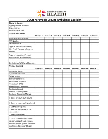
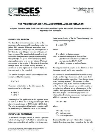
The key air vehicle and propulsion systems technologies selected for incorporation are depicted in Fig. 1. Thispaper focuses on the evolutionary path followed to develop these technologies. The final F-35 aircraft subsystems[35], propulsion [36], and mission systems [37], as well as the SDD program, are discussed in greater detail insupporting publications. Each of the items featured in Fig. 1 represents a significant aircraft capability enhancementthat added to the overall success of the F-35 configuration. Successes in the associated development programs forthese led to their incorporation into the F-35 design baseline entering the SDD program.Fig. 1 Advanced technologies selected for F-35 air vehicle and propulsion systems incorporation.The various development projects that evolved into the systems configurations used in the F-35 spanned the 1990sduring the period preceding the winner of the JSF competition. Figure 2 provides key development milestones leadingto the incorporation of selected technologies into the F-35 program.The J/IST integrated subsystems development occurred in parallel with the Concept Development Program (CDP).Interestingly, in it the various JSF competitors cooperated in a collaborative environment, sharing all results and data.This allowed the risk reduction activities associated with the integrated vehicle systems to be pursued without the needto encumber the Concept Demonstrator Aircraft (CDA) aircraft schedule, and enabled the final results and lessonslearned to be incorporated into the F-35 at the outset of the SDD program.During the same period, numerous IRAD and CRAD studies evaluating potential propulsion innovationscontinued. As with the J/IST results, several of these were incorporated into the F-35 after the SDD contract award.Significant technical risks associated with the diverter-less supersonic inlet (DSI) and LO axisymmetric nozzle, andSTOVL propulsion system configurations were retired in parallel with the CDA work, culminating in flightdemonstrations showing the maturity and efficacy of the concepts. As an example, dual-redundancy features of theSTOVL exhaust nozzle were developed in parallel with the CDA program and incorporated during SDD.Approved for public release 5/8/18, JSF18-3652
Fig. 2 JSF program air vehicle and propulsion systems technology development roadmap.II.Integrated Air Vehicle SubsystemsA. Early Design StudiesAircraft subsystems have traditionally been designed using a federated approach consisting of a number ofindependently designed subsystems. JSF-sponsored studies showed the potential for significant benefits fromintegrating these functions. This applied to three subsystems: flight controls and actuation systems, electrical andauxiliary power systems, and the environmental control system (ECS). Results from the studies showed that theeffective integration of these three key subsystems could significantly improve aircraft performance and dramaticallyreduce the amount of equipment required. In doing so, it would provide improved affordability and warfightingbenefits essential to F-35 program goals.In conventional systems, electrical, hydraulic, pneumatic, and mechanical power are generated and distributedfrom the engines and auxiliary power system. The government-funded SUIT [1-7], MEA, and VITPS [8-9] studiesshowed the potential benefits of eliminating or shrinking the conventional centralized hydraulic system. They alsoshowed the potential benefits of reducing engine bleed air extraction [1-7]. AFRL sponsored SUIT in the late 1980sand early 1990s to look into what could be gained from more efficient integrations of selected air vehicle subsystems[39]. The original SUIT concept was to replace single-function subsystem equipment with multifunctional hardware,potentially reducing volume and weight while increasing overall efficiency. Later, the objective of using the engine’sfan air stream as a sink for waste heat from the subsystems was added. Concurrently, AFRL’s propulsion laboratorywas independently pursuing MEA technology, including electrically powered flight control actuation and robustelectric power generation and distribution system concepts. As a result, MEA system and component technologieswere undergoing development and testing through several separate and independent initiatives.Between 1994 and 1995 the JAST program identified key technology building blocks to support the developmentof an advanced strike capability. The idea was to screen candidate technologies for their applicability based on theirrespective payoffs with regard to the four JSF program pillars: affordability, lethality, survivability, and supportability.At that time, three weapons systems contractors (WSCs) were actively competing to win JSF: Lockheed Martin,Approved for public release 5/8/18, JSF18-3653
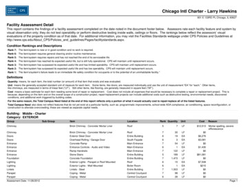
Boeing, and the McDonnell Douglas (later Boeing St. Louis)/Northrop Grumman/BAE Systems team. The candidateJSF configuration was expected to be a single-seat, single-engine strike aircraft, largely due to affordabilityconsiderations. Originally, the JSF platform focused on Air Force and Navy customers. However, during JAST thegovernment concluded that the advanced STOVL (ASTOVL) concept development should be rolled into JAST/JSF.Thus, the STOVL jet was added to the JSF design space [39]. JAST initiated the VITPS studies [8-9]. All three WSCsconcluded that SUIT and MEA technologies could be combined synergistically in a strike aircraft. Accordingly, theyrecommended that the SUIT/MEA combination be pursued under JAST. Each WSC advocated pursuing integratedsubsystem technology, and from that advocacy the J/IST demonstration program was conceived.B. JSF Integrated Systems Technology Demonstration ProgramThe goals of the J/IST demonstration program were to set the stage for the JSF SDD program and sharpen thefocus for the target JSF platform configuration. Ultimately, that configuration was shaped by the winning proposal forwhat would become be the largest acquisition program in Department of Defense history. The J/IST program was tobe executed by all three WSCs competing for the JSF. Each WSC was supporting its own JSF proposal team whilesimultaneously being responsible to the other JSF WSCs for the technical results of the J/IST work.The J/IST government team ensured that each participating WSC team was contractually accountable to andexecuting on behalf of the other WSCs. Each participant was treated by the government as customers for thetechnologies being demonstrated. This arrangement provided a level playing field using WSC input to make all keydecisions within the scope and resources of the program. This fostered trust, a sense of fair play, and governmentresponsiveness within the otherwise highly competitive JSF program environment. In turn, that collaborativeenvironment enabled the results of each element of the studies to be capitalized by each competing contractor. Directinvolvement of the three WSCs was fortuitous, as it compelled expanded involvement and cooperation beyond whatotherwise might have been the case [39]. Each WSC benefitted from the combined J/IST demonstration results, asthese provided information to be used in each WSC’s preferred weapons system configuration aircraft proposals.The focus of the J/IST demonstration program was to reduce the risks associated with subsystem integrationtechnologies. This applied specifically to MEA technologies, including switched-reluctance (SR) starter/generators(S/Gs), electro-hydrostatic actuation system (EHAS) integration, and thermal/energy management module (T/EMM)integration through a series of maturation efforts. The work included developing and flight testing prototype versionsof the SR S/G and electro-hydrostatic actuation (EHA) flight control actuators, successfully reducing the risks in thesetechnologies from high to low for the SDD program. The work was divided into three main focus areas: one focusingon the electrical power and flight control actuation system (led by Lockheed Martin), one focusing on the developmentof T/EMM-related technologies (led by Boeing St. Louis), and one dedicated to independent benefit assessments (ledby Boeing at its Seattle facility).Figure 3 compares a conventional federated subsystems architecture to the F-35 integrated subsystemsarchitectures. The integrated architectures reduced system parts count, which led to smaller, lighter, and lower-costaircraft. Based on those conclusions and the configuration design developed for the SDD program, these systems wereincorporated into the F-35 baseline.The J/IST program was instrumental in reducing the risk of integrating these technologies prior to entering the JSFSDD program in 2001. The J/IST conclusions indicated an overall reduction in life-cycle costs (LCC) projected to be2 to 3 percent, compared to the LCC of a similar legacy configuration [19]. The benefits of these integratedtechnologies are highlighted in Fig. 4.Approved for public release 5/8/18, JSF18-3654
Fig. 3 F-35 integrated vehicle systems.Fig. 4 Benefits of integrated subsystems technologies.1. J/IST Electrical Power System and Electro-Hydrostatic Actuation SystemThe Lockheed Martin-led team achieved the following key accomplishments in the J/IST program:1) Development and flight test of an SR, dual-channel S/G system to provide a fault-tolerant, redundant270 VDC electrical power source for a single-engine fighter aircraft;2) Development of a dual-redundant, flight-qualified electric actuation system;3) Development of a flight-qualified 270 VDC battery system to provide uninterruptible electrical powerto the flight-critical 270 VDC electrical power system (EPS);4) Development of a flight-qualified emergency power system to provide a secondary power source;5) Completion of specific technology demonstration tests on the S/G to verify operation under certain faultconditions;Approved for public release 5/8/18, JSF18-3655
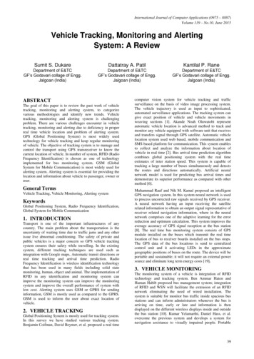
6) Modification, integration, and flight test of the above technologies in a single-engine advanced flighttechnology integration (AFTI)/F-16 aircraft (Fig. 5); and7) Validation of MEA technologies with an AFTI/F-16 demonstration for the F-35 subsystems suite.Fig. 5 AFTI/F-16 J/IST aircraft MEA technologies and transition to F-35.J/IST Electrical Power SystemImmediately following J/IST contract award, Hamilton Sundstrand (now a UTC Aerospace Systems [UTAS]company) was selected to develop and qualify the SR generator system. UTAS was involved in the initial Air ForceSR technology development and proposed using the same 250 kW 270 VDC generator design. However, UTAS ratedit for 80 kW and packaged it for the F-16 application. The primary focus was on using an SR generator system, butthe fault tolerance and redundancy of the 270 VDC power were emphasized as well. This included an emergencygenerator and a 270 VDC battery. The AFTI/F-16’s EPS was modified significantly to support the J/IST program’sMEA technologies. These consisted of one 270 VDC EHAS for the five primary flight control surfaces, two 270 VDCfuel pumps, one 270-to-28 VDC converter, and one 270 VDC-to-115 VAC inverter.AFTI/F-16’s pre-J/IST electrical system was a combination of an F-16 Block 15 production system and a digitalflight control power system (production Block 40), receiving only 115 VAC and 28 VDC power. Therefore, to supportthe legacy F-16 equipment and MEA systems, the electrical system was modified to provide 270 VDC, 115 VAC, and28 VDC power. During the initial program’s design phase, it was determined that the MEA systems would consumethe most power. Accordingly, the primary power type would be 270 VDC power. Also, since the EHAS is a flight-Approved for public release 5/8/18, JSF18-3656
critical system, the 270 VDC system would be designed to be fault tolerant and provide limited uninterruptible power.For EPS integration, the primary challenges were:1) SR S/G flight certification,2) fault-tolerant power generation and distribution,3) 270 VDC power system stability with multiple variable power loads,4) 270 VDC fill-in battery operation, and5) electromagnetic interference (EMI) and electromagnetic compatibility (EMC).The following combination of components provided the baseline design for the J/IST engine S/G (ES/G) system.The inverter/converter/controller (ICC) for the ES/G system was taken from the UTAS LV100 SR S/G system. Thepower electronics converter and the SR generator were taken from the UTAS/General Electric Integrated HighPerformance Turbine Engine Technology (IHPTET) research program. The ES/G system was required in two tests:the AFTI/F-16 flight test and a ground test. For the flight test it was used to demonstrate generation capability in anMEA application. For the ground test, it demonstrated motor, start, and generation capabilities. The ground testapplication included a demonstration of starting a Pratt & Whitney F119 engine and transitioning to generate mode.The ES/G system was designed to accommodate all applications. However, the ICC package design was driven by theAFTI/F-16 installation. Both the flight and ground demonstrations used nearly identical hardware, with minor changesmade to adapt to their respective operating environments. The resultant J/IST MEA architecture is shown in Fig. 6.Fig. 6 AFTI F-16 J/IST electrical power and actuation flight demonstration architecture.The ground demonstrations exercised all the capabilities of the ES/G system, specifically its engine motoring andstarting, power generation, and fault tolerance. The T/EMM motor/generator system provided 270 VDC power to theICCs for engine motoring and starting. The ES/G system was transitioned from start to generate to provide 270 VDCpower to two primary motor buses. Modifications were made to the ES/G and ICCs from the AFTI/F-16 configurationto enable bidirectional power flow and increased speed range operation.J/IST Electrically Powered Flight Control SystemParker Aerospace was selected to provide the EHAS for the F-16. The company had previously developedprototype EHAs for various ground and flight test programs. Among them were the flight tests of an aileron actuatoron the Lockheed Martin C-130 high-technology testbed. Previous electric actuation integration programs focused onApproved for public release 5/8/18, JSF18-3657
single-surface operation or non-flight-critical control surfaces. Two examples are the F/A-18 Electrically PoweredActuation Development (EPAD) and F-15 Fly by Light Advanced Systems Hardware (FLASH) programs. Bycontrast, J/IST focused on integrating all primary flight control surfaces, with no hydromechanical backup system.This bold approach was essential to convincingly prove that the MEA concept supported the JSF technology transitioncriteria.Lockheed Martin worked closely with Parker Aerospace to define the EHAS system-level requirements,integration test requirements, and software configuration management. The development and testing of the EHAS wasthe most challenging of the contracted tasks. The selection of the F-16 as the flight vehicle provided known air vehicleand system-level requirements, which made the development task easier. However, multiple hardware and softwaredevelopment challenges were encountered that provided valuable lessons learned for the SDD program.The Lockheed Martin team conducted a detailed design of two EHASs: one to replace the F-16 flaperon andhorizontal tail integrated servo-actuators (ISAs), and one to replace the F-16 rudder ISA (Fig. 7). The designsincorporated a common power electronics package for all five actuation systems. The Lockheed Martin team alsoprovided an analog interface with the existing F-16 digital flight control computer (DFLCC). To do so, it developedand integrated a separate interface box that required no major flight control software or hardware changes to theDFLCC. This approach resulted in four major component designs: an F-16 flaperon/horizontal tail dual-tandem EHA,an F-16 rudder dual-tandem EHA, a common power drive electronics package, and an EHA interface controllerelectronics unit.Fig. 7 Key AFTI F-16 modifications.EHAS integration testing of all five actuators with electronics was successfully completed at Parker Aerospace’sfacility. The testing verified that the hardware and software met all design requirements. Further, it provided detailedvisibility into the system’s operation and added confidence in the EHAS software. It also reduced risk in the integrationof the system into the AFTI/F-16 aircraft. The few technical issues discovered were resolved in the laboratoryenvironment, avoiding the risks of discovery on aircraft. Throughout the on-aircraft flight control integration and test,minimal EHAS changes were required.The power and actuation flight demonstration provided key technical proof to mature MEA technologies for theJSF EMD phase. This demonstration tested the external S/G, the 270 VDC power distribution system, and the EHAsin a realistic aircraft environment. It provided valuable integration and installation data for thermal environment,Approved for public release 5/8/18, JSF18-3658
EMI/EMC, and supportability, among other areas. The AFTI/F-16 modifications were successfully demonstrated inthe aircraft, with the key highlights including:1) nine flights accomplished totaling 13 flight hours, performing realistic JSF-like mission profiles;2) flight envelope including Mach 1.3 (600-knot engine limitation), up to 30,000 feet altitude (ferry); and3) test pilots reporting no observable difference in handling qualities, compared to a baseline F-16.For its achievements, the AFTI/F-16 flight demonstration won Flight International magazine’s 2000 AerospaceIndustry Award for Engineering, Maintenance and Modification, presented at the Paris Air Show in 2001 [40].2. J/IST Thermal/Energy Management ModuleBoeing St. Louis (formerly McDonnell Douglas) led an industry team responsible for the subsystem architecturesand ground demonstrations of power and cooling integration, and electric actuation and power system integration [11].Major participants in the team were Honeywell Aerospace (formerly AlliedSignal Aerospace Inc.), BAE Systems(formerly Astronics Corporation), Moog Inc., Northrop Grumman, and Pratt & Whitney. The team achieved thefollowing key accomplishments in the J/IST program:1) Development of an integrated T/EMM system:a. T/EMM turbomachine,b. high-temperature air/fuel heat exchanger,c. air/liquid heat exchanger,d. engine fan duct air-to-air heat exchanger,e. dual-mode recuperator heat exchanger,f. T/EMM integral S/G, andg. T/EMM controller and vehicle management computer interface.2) Development of the T/EMM system controls and modes of operation;3) Demonstration of integrating the power and cooling subsystems into a stand-alone integration environment;and4) Demonstration of the integration of the T/EMM integrated subsystems with the engine.The team selected a generic, JSF-like aircraft for assessing and defining the J/IST requirements. These includedrequirements for power, cooling, and actuation systems of the aircraft for ground, flight, and emergency operatingconditions. The subsystem architecture that was developed resulted in the consensus architecture configurationdepicted in Fig. 8. This architecture used the engine fan duct as a heat sink and integrated the functions traditionallyperformed by the ECS, auxiliary power unit (APU), and emergency power unit (EPU). The system was designed tosupport requirements for electrically powered flight control actuation and electric start of the main engine usingT/EMM power to drive the ES/G.Approved for public release 5/8/18, JSF18-3659
Fig. 8 J/IST T/EMM architecture.Thermal/Energy Management Module RequirementsThe T/EMM system architecture was intended to perform all functions normally accomplished by a traditionalaircraft ECS, auxiliary power system, and emergency power subsystems. The T/EMM was required to provideadditional capabilities expected to be required in the F-35, including cooling high-powered electronics. Thisrequirement drove the requirement in J/IST for a backup cooling capability to accommodate inflight failures andprovide active cooling for Navy hangar deck maintenance. The operating requirements created a need to developmultiple modes of operation and reconfigure the system between these modes as required to perform the differingfunctions. Consequently, the following operating modes were developed and demonstrated in the J/IST effort:1) Mode 1.0 – Electrically powered hangar deck cooling,2) Mode 2.0 – Stand-alone T/EMM start,3) Mode 3.0 – Cooling and electrical power for ground maintenance,4) Mode 5.0 – Electrical power for main engine start,5) Mode 6.0 – Engine bleed air-driven cooling and triplex electrical power (normal flight),6) Mode 7.0 – Engine bleed air-driven cooling and emergency electrical power (failure of the ES/G),7) Mode 8.0 – Emergency electrical power (failure of the ES/G),8) Mode 9.0 – Stand-alone emergency electrical power – stored air (engine failure at high altitude),9) Mode 10.0 – Stand-alone emergency cooling and electrical power – ambient air (engine failure at lowaltitude),10) Mode 11.0 – Shutdown, and11) Mode 12.0 – Emergency cooling – fuel heat sink (not demonstrated in J/IST).Thermal/Energy Management Module Turbomachine and Component DevelopmentThe design and development of a full-scale T/EMM turbomachine was accomplished by Honeywell Aerospace inPhoenix, Arizona. The turbomachine configuration incorporated a power turbine, compressor, SR integral S/G (IS/G)rotor, and cooling turbine on a single spool that operated at speeds up to 60,950 rpm (Fig. 9). The compressor andpower turbine were mounted on a single shaft, and the IS/G and cooling turbine were mounted on a separate singleshaft. The two shafts were connected by a floating quill shaft, resulting in a design that provided sufficient marginfrom high-speed shaft bending modes. This split allowed each section to be developed and tested independently. TheApproved for public release 5/8/18, JSF18-36510
power turbine used a variable geometry stator with movable vanes that allowed for performance optimization at thevarious operating conditions. The turbomachine included a canister type combustor developed specifically for theT/EMM that featured three distinct modes (tri-mode combustor) and was subsequently patented by Honeywell.Fig. 9 T/EMM turbomachine cross-section.Additional components making up the T/EMM configuration requiring significant development were the SR I/SGconfiguration, T/EMM controller, and various other heat exchangers, valves, and related components.In parallel with the Honeywell T/EMM development projects, Pratt & Whitney integrated the Honeywell-designedfan duct heat exchangers into a modified F119 engine. This was another key success supporting the claim that theT/EMM concept was viable and supported the JSF technology transition criteria.T/EMM System DemonstrationsSeveral significant demonstrations were accomplished in support of the J/IST team effort. Figure 10 summarizesthe major demonstrations, building up from the component level to successively higher levels of integration. One ofthe three most significant demonstrations was the integration of the power and cooling subsystems into a stand-aloneintegration environment. Another of the three was the electrical integration of T/EMM and ES/G, high-power EHAintegration testing, and EMI testing. The third was the demonstration of the integration of the T/EMM integratedsubsystems with the engine.The stand-alone integration demonstration began in the summer of 1999 at Honeywell in Torrance, California.The demonstration, which simulated a mission profile, included ground maintenance operation with 25 kW ofelectrical power and 12 kW of cooling. It also included normal-engine-bleed air-driven operation during taxi, takeoff,acceleration, climb, cruise, loiter, descent, and landing. In addition, it showed emergency operations that simulatedthe loss of the engine and ES/G failure. The results demonstrated the capability to perform all the required modes andsuccessfully reconfigure between modes as required. Post-test comparisons of test data with the dynamic modelconfirmed the model’s ability to predict results. The comparisons also reinforced the value of the virtual modelingeffort prior to commencing hardware operations.The electrical power management integration of T/EMM and ES/G was conducted at Northrop Grumman’s facilityin El Segundo, California. The testing demonstrated that the IS/G-integrated EPS could provide the needed capabilityto power the ES/G using IS/G power to start the F119 engine. The testing also showed that the system could providethe necessary emergency power requirements, and that its generators could handle the dynamic loads imposed by thehigh-power EHAs.The final engine integration demonstration was performed in 2000 at Pratt & Whitney’s facility in West PalmBeach, Florida. It brought Honeywell’s T/EMM system, Northrop Grumman’s EPS, and Hamilton Sundstrand’s(UTAS’) ES/G together with a modified Pratt & Whitney F119 engine. With this combination, it validated theintegrated subsystems concept. The Hamilton Sundstrand (UTAS) ES/G was connected to the engine using a speedincreaser gearbox. The Honeywell T/EMM system was connected to the engine wi
Systems Engineering Senior Staff Specialist, F-35 Power and Thermal Management System, 1 Lockheed Blvd. 2. Director, F-35 Air Vehicle, 1 Lockheed Blvd. 3. Systems Engineering Senior Manager, F-35 Vehicle Sciences and Systems, 1 Lockheed Blvd. 4. Lockheed Martin Senior Fellow, F-35 Air Vehicle, 1 Lockheed Blvd. 5