Transcription
AST-CAN485 Hookup GuideIntroductionThe AST-CAN485 is a miniature Arduino in the compact form factor of the Arduino Pro Mini. In addition to all the usual features it has on-board CANand RS485 ports enabling quick and easy interfacing to a multitude of industrial devices. The CAN485 bridges the gap between the maker andindustrial spaces.SparkFun AST-CAN485 Dev Board DEV-14483The CAN485 builds on the popular Arduino platform. It is pin-compatible with the Arduino Pro Mini, giving it a small form factor ideal for embedding inprojects. It supports the Arduino IDE, the Arduino core libraries, and can be installed using the boards manager. Libraries are provided to support theCAN and RS485 ports. On-board CAN and RS485 transceivers allow for out of the box interfacing to any CAN or RS485 based network. CAN andRS485 form the backbone of many communications protocols with applications in automation, industrial systems, building management, automotivesystems, OBDII, and many more.Product Showcase: SparkFun AST-CAN485 Dev BoardSuggested ReadingIf you aren’t familiar with the following concepts, we recommend checking out these tutorials before continuing.
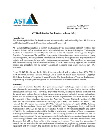
How to Solder: Through-Hole SolderingSerial CommunicationThis tutorial covers everything you need to know about through-holesoldering.Asynchronous serial communication concepts: packets, signal levels,baud rates, UARTs and more!What is an Arduino?Installing Arduino IDEWhat is this 'Arduino' thing anyway?A step-by-step guide to installing and testing the Arduino software onWindows, Mac, and Linux.Logic LevelsResistorsLearn the difference between 3.3V and 5V devices and logic levels.A tutorial on all things resistors. What is a resistor, how do they behave inparallel/series, decoding the resistor color codes, and resistorapplications.Hardware OverviewThe CAN485 adopts the same tiny form factor as the Pro Mini measuring about 34.65mm x 19.20mm, making it easily embeddable in applicationswhere space is limited. The pin layout is the same as the Arduino Pro Mini. This makes it pin compatible with existing Pro Mini shields and applications.An additional row of pins below the RESET button on the fourth side contains the CAN and RS485 ports.AST-CAN485 DimensionsPinoutArduino Pro Mini Dimensions
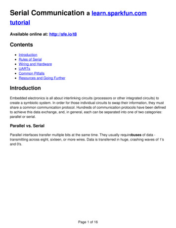
While the pin assignments are similar to the Arduino Pro Mini, there are some differences in their functions. Care should be taken when using shieldsdesigned for the Pro Mini with the CAN485. The graphical datasheet gives more details about the pins and their functions.Having a hard time seeing the image? Click the image for a closer look.The CAN485 is based on the Atmel AT90CAN128 processor. The processor runs at 16MHz, has 128KB or Flash, 4KB of SRAM and features ahardware CAN controller. The CAN485 breaks out commonly used communications ports and pin functions including: I2C, SPI, UARTs, 8 analog inputs,and 6 interrupt enabled pins.More information can be found on the AT90CAN128 datasheet and AST-CAN485 schematic.Note for Advanced Users: The CAN485's AT90CAN128 uses an Arduino bootloader. For those that are trying to flash the chip with an AVRprogrammer and Atmel Studio, the ICSP pins are not in a location that you would expect. Instead of the SPI pins for D12 (MISO) and D11(MOSI),it is actually located on the FTDI's header pins D1 (TX0) and D0 (RXI) :Target's External Power5VGNDCAN485AVR ProgrammerD1 (TX0) on FTDI HeaderMISOD13 (SCK)SCKRSTRST5V5VD0 (RXI) on FTDI HeaderMOSIGNDGNDMore information can be found on page 349 of the AT90CAN128 datasheet in section 25.7 for SPI Serial Programming.PowerThere are several ways that the CAN485 can be powered.The CAN485 has an on-board regulator allowing for an unregulated input voltage to be supplied on the RAW pin. The allowable input voltage range is7-16V, however 7-12V is recommended.
Note: Input voltage should be kept under 12V if the CAN port is being used at the same time as more than 5 digital outputs.A regulated 5V supply may also be supplied directly to Vcc. Supplied voltage must be in the range 4.5V to 5.5V. Power can also be supplied to theFTDI header by a FTDI breakout.Warning: Incorrect power supply may cause damage to the CAN485 or other connected devices.Once the board is powered, the PWR led will light up.FTDI Programming HeaderLike the Pro Mini, the CAN485 has no on-board USB connection. An external FTDI breakout board is required to program the board or connect it to aPC.To connect, you would need a 5V FTDI, header pins to connect, and a mini-B USB cable.SparkFun FTDI Basic Breakout - 5VBreak Away Headers - Straight DEV-09716 PRT-00116
SparkFun USB Mini-B Cable - 6 Foot CAB-11301CAN PortThe CAN controller is hardware accelerated, allowing for high speed CAN communication with minimal processor overhead. The on-board CANtransceiver means the CAN485 can be directly connected to a CAN network with no additional electronics.AST-CAN485 Front Side: CAN PortAST-CAN485 Front Side: CAN IC and PortConnecting to a CAN NetworkThe image below shows a typical connection between the CAN485 and a CAN network. The network consists of two lines (CANH and CANL). Multipledevices may be connected in parallel on these lines. The bus must be terminated at each end with termination resistor (typically 100Ω to 120Ω).For more information, check out the Introduction to CAN Bus.RS485 PortSimilar to the CAN port, the CAN485 features an on-board RS485 transceiver which allows for simple connection to any RS485 network. While UART1is consumed by the RS485 port, it is also broken out on pins 22 and 23 if the user would rather use it as a serial port.
AST-CAN485 Front Side: RS485 PortAST-CAN485 Back Side: RS485 IC and PortConnecting to a RS485 networkThe image below shows a typical connection between the CAN485 and a RS485 network. The network consists of two lines (A and B), devices areconnected in parallel on these lines. The bus must be terminated at each end with a termination resistor (typically 100Ω to 120Ω)For more information, check out the Introduction to RS485.JTAGThe JTAG programming and debugging interface is broken out on pins 18-21. This allows for more advanced debugging with Atmel Studio users.One important implication is that in order to use these pins for I/O, the JTAG interface must be disabled. This can be done by adding a small bit of codeto the setup() function.AST JTAG SOFTWARE DISABLE.INOSoftware Serial w/ AltSoftSerialUnfortunately, the AT90CAN128 chip’s pins do not support change interrupts. Therefore, the Arduino SoftwareSerial library is not supported. TheAltSoftSerial library may be used as an alternative.There are some limitations associated with the AltSoftSerial library. It uses a Timer resource on the microprocessor. Only one Timer is available so onlyone AltSoftSerial port is available and it is fixed on pins 5 and 9. AST modified the standard AltSoftSerial library to support the CAN485. The library isavailable on AST’s GitHub.
AST ALTSOFTSERIAL LIBRARYHardware HookupThe CAN485 does not come with headers soldered on. We’ve left it up to you to solder on the headers or wires to the board for your project. Optionsinclude stackable headers, bent headers, or soldering wires directly to the pin pads.Break Away Headers - StraightBreak Away Male Headers - Right Angle PRT-00116 PRT-00553Photon Stackable Header - 12 Pin PRT-14322If you are new to soldering, check out the tutorial on through hole soldering. You will need a soldering iron, solder, and general soldering accessories.Hakko FX888D Soldering StationSolder Lead Free - 100-gram Spool TOL-11704 TOL-09325A standard configuration for prototyping is to have the pins on the side facing down to allow for easy breadboarding while having the FTDI facing outand communications pins facing up for access via jumper cables.Software Installation
Note: You will need to upgrade if you are using a version older than 1.6.3. This example assumes you are using the latest version of the ArduinoIDE on your desktop. If this is your first time using Arduino, please review our tutorial on installing the Arduino IDE. If you have not previouslyinstalled an Arduino library, please check out our installation guide.The next step is to install the CAN485 board into the Arduino IDE. There are two methods of installation. The first is by using the Arduino BoardsManager, this is the preferred method. The second method is to manually copy files from the GitHub repository.Board Installation Using the Boards ManagerUsing the Arduino IDE’s boards manager is the preferred installation method.Open the preferences window (File Preferences) in the Arduino IDE. Copy the following URL and add it to the list of boards manager er/package ast boards index.jsonOpen the boards manager (Tools Board Boards Manager ):Scroll to AST AVR Boards and click on the Install button:
The AST AVR boards will now be available under the boards menu. Select the Can485 when uploading to the development board.Manual InstallationTo manually install the AST AVR Board add-on:Download the AST Arduino-Boards-Packages.Unzip the folder.Unzip the ast-0.0.1.zip folder.Move the ast folder into: MyDocuments/Arduino/hardware/ .To manually install the CAN library:Download the CAN library repository from GitHubUnzip into the Arduino libraries Folder: /MyDocuments/Arduino/libraries/ .(Create the libraries folder if it does not exist)The final directory structure should be: /MyDocuments/Arduino/libraries/AST CanLib .To manually install the RS485 library:Download the RS485 library repository from GitHubUnzip into the Arduino libraries Folder: /MyDocuments/Arduino/libraries/(Create the libraries folder if it does not exist)The final directory structure should be: /MyDocuments/Arduino/libraries/AST RS485 .Uploading CodeConnect the FTDI programming cable to the FTDI header as shown:Open the Arduino IDE and select the CAN485 board in the tools menu. Ensure that the correct COM port is being used. Upload the Blink example(Examples 01.Basics Blink).Introduction to CAN BusHeads up! This section gives a brief overview of some of the important features of CAN bus. For more detailed information refer to the linksprovided in the Resource and Going Further.
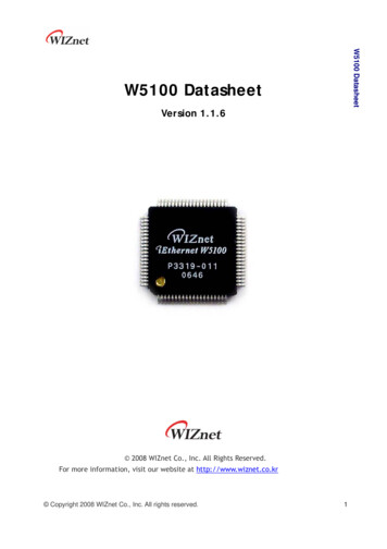
The Controller Area Network (CAN) bus is a communications standard with its origins in the automotive industry. It has several built in features thatmake it robust and noise tolerant. It is a message based protocol that is able to support multiple nodes. Speeds up to 1Mbps are supported overdistances less than 40m while longer distances are possible at lower speeds (500m at 125Kbps). CAN bus also features an arbitration method whichautomatically prioritizes messages and resolves packet collisions.CAN is used as a field bus in industrial applications and comprises the lower layer on top of which many higher-layer protocols are based. CANopenand DeviceNet are common higher layer protocols based on CAN bus and used in industrial automation. CAN bus is also used in the OBDII vehiclediagnostics standard which is mandatory on modern cars in the US and EU.Signal DescriptionA CAN bus consists of two signals (CAN H and CAN L) and terminated at each end with a termination resistor (typically 100Ω to 120Ω). These lines areusually wound into a twisted pair.The bus has a recessive state (Logic 1) and a dominant state (logic 0). The bus needs to be actively driven to the dominant state by one of the nodes. Ifit is not driven to the dominant state by any of the nodes, the bus will return to the recessive state. This dominant and recessive behavior means that iftwo nodes transmit at the same time, the dominant bits will take preference. A method of arbitration takes advantage of this behavior to resolve packetcollisions.A CAN transceiver is necessary to translate between the line states and the logical states used by a microprocessor.Having a hard time seeing the image? Click the image for a closer look.Network StructureMultiple nodes may be connected in parallel. The lines must be terminated on each end with a termination resistor (typically 100Ω to 120Ω).Packet StructureCAN messages have a standard format consisting of a message ID, a data length field, a data frame, a CRC and other control bits. Being a messagebased protocol, there are no node addresses, instead there is a message ID. Data is associated with an ID as opposed to a device and one node maytransmit using several message IDs. This behavior can be very useful. For example, a node can report motor speed, position and acceleration on threedifferent message IDs, allowing for easy identification of parameters by any receiving nodes.Message IDs should be unique. If two nodes attempt to send a message with the same ID at the same time, it will cause an error. The message ID isalso used in the arbitration process to determine which message has priority when two nodes attempt to transmit at the same time.There are two standard formats for CAN packets, the base format (CAN2.0A) and the extended format (CAN2.0B). The extended format features a 29bit ID while the base format features an 11-bit ID. The extended format is backwards compatible, allowing for both formats to be used on any CANnetwork.Having a hard time seeing the image? Click the image for a closer look.ArbitrationWhen two nodes attempt to transmit at the same time an arbitration process determines which one takes preference. While transmitting, each nodereads the bus state as well. If a node detects that one of its recessive bits has been driven dominant by another node, then it stops transmitting. Thisresults in lower IDs taking precedence over higher IDs. If a node looses arbitration, it will attempt to resend the message once the current transmissionis complete. This behavior results in automatic prioritization and collision resolution.
Having a hard time seeing the i
and RS485 ports enabling quick and easy interfacing to a multitude of industrial devices. The CAN485 bridges the gap between the maker and industrial spaces. The CAN485 builds on the popular Arduino platform. It is pin-compatible with the Arduino Pro Mini, giving it a small form factor ideal for embedding in projects. It supports the Arduino IDE, the Arduino core libraries, and can be .