Transcription
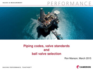
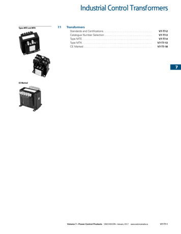
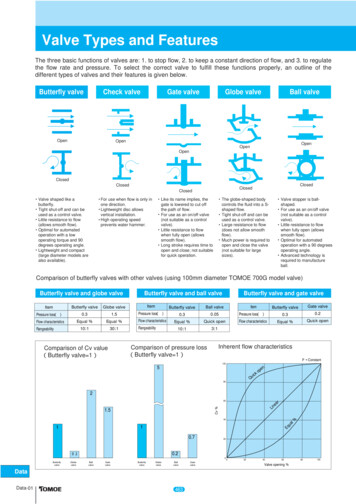
Valve Types and FeaturesThe three basic functions of valves are: 1. to stop flow, 2. to keep a constant direction of flow, and 3. to regulatethe flow rate and pressure. To select the correct valve to fulfill these functions properly, an outline of thedifferent types of valves and their features is given below.Butterfly valveCheck valveOpenOpenGate valveGlobe valveBall valveOpenOpenOpenClosedClosedValve shaped like abutterfly.Tight shut-off and can beused as a control valve.Little resistance to flow(allows smooth flow).Optimal for automatedoperation with a lowoperating torque and 90degrees operating angle.Lightweight and compact(large diameter models arealso available).For use when flow is only inone direction.Lightweight disc allowsvertical installation.High operating speedprevents water hammer.ClosedClosedClosedLike its name implies, thegate is lowered to cut offthe path of flow.For use as an on/off valve(not suitable as a controlvalve).Little resistance to flowwhen fully open (allowssmooth flow).Long stroke requires time toopen and close; not suitablefor quick operation.The globe-shaped bodycontrols the fluid into a Sshaped flow.Tight shut-off and can beused as a control valve.Large resistance to flow(does not allow smoothflow).Much power is required toopen and close the valve(not suitable for largesizes).Valve stopper is ballshaped.For use as an on/off valve(not suitable as a controlvalve).Little resistance to flowwhen fully open (allowssmooth flow).Optimal for automatedoperation with a 90 degreesoperating angle.Advanced technology isrequired to manufactureball.Comparison of butterfly valves with other valves (using 100mm diameter TOMOE 700G model valve)Butterfly valve and globe valveButterfly valve and ball valveButterfly valve and gate valveItemButterfly valveGlobe valveItemButterfly valveBall valvePressure loss(ξ)0.31.5Pressure loss(ξ)0.30.05Pressure loss(ξ)0.30.2Flow characteristicsEqual %Equal %Flow characteristicsEqual %Quick openFlow characteristicsEqual %Quick open10:130:110:13:1RangeabilityComparison of Cv value(Butterfly valve 1)RangeabilityComparison of pressure loss(Butterfly valve 1)ItemGate valveButterfly valveInherent flow characteristics P Constant1005npekoicQu80260reaLinCv ata-01Equal%40463Gatevalve0204060Valve opening %80100
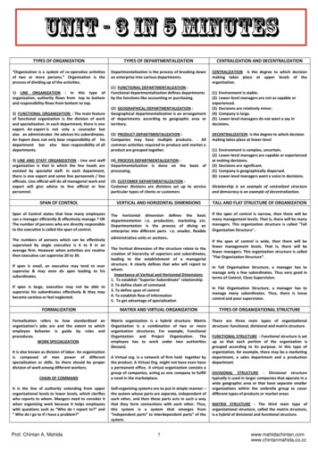
Valve Sizing ProceduresIt is essential to understand the valve sizing formula and selection procedure when determining the size of avalve. The following is the proper selection procedure. The valve sizing calculation is based on ISA.1. Judge if the flow condition is subcritical or critical based on the given flow condition.2. Calculate the Cv value by putting the data into an appropriate formula.3. Select the size of the valve using the Cv value chart. Consider the following points when sizing the valve.q A proper adjustment of the Cv calculation should be made based on the piping adjustment coefficientFp if a valve is located between reducers.w If the result of the Cv calculation is over 80% compared to the full Cv value, select a valve one sizelarger.Example: For fresh water with P1 0.3 MPa, P2 0.25 MPa, flow rate 100 m3/h, the calculated Cvwill be 164. If 80 mm, 507V is selected, the rated Cv is 176. The calculated Cv (164) is over 80% ofrated the Cv (176) in this case. We recommend 100 mm, 507V.e If no P is given, 5 to 10% of the pump outlet pressure should be used as the assumed P for valvesizing.Data464Data-02
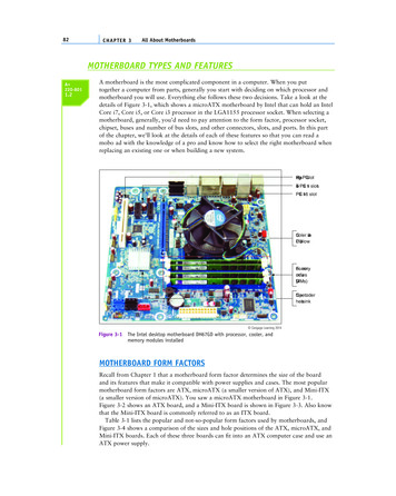
Cv Value CalculationCv value calculationDataData-03465
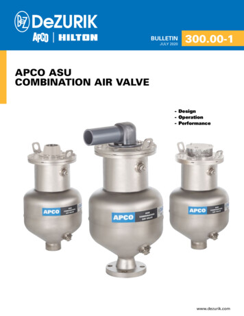
Symbol LegendSymbolCv: Valve flow coefficientFL: Pressure recovery coefficientG: Specific gravity of gas(Air 1)Gf: Specific gravity at valve-inlet temperature(Water 1 at 15 degrees C)P1: Valve-inlet pressure(kPaA)P2: Valve-outlet pressure(kPaA) P: Pressure difference across valve [P1 — P2](kPa)Pc: Critical pressure(kPaA)Pv: Saturated vapour pressure of liquid at valve-inlet temperature (kPaA) PS: Max. DP for sizing Working conditions: Outlet pressure is higher than vapour pressure. PS P1 — Pv(kPa) Working conditions: Outlet pressure is equal to or lower than vapour pressure.DPS P1 — 0.96 0.28PvPCPv(kPa)(m3 / h)(m3 / h)q: Volume flow rate of liquidQ: Volume flow rate of gas [At 15 degrees C, 1 atm] Nm3/h 288273T: Fluid temperature [273 degrees C]Tsh: Degree of superheat T — TcTc: Saturated vapour temperature at valve-inlet pressureW: Mass flow rate (T / h) (1,000 kg / h)(K)(degrees C)(K)Calculation for piping geometry factorFp Fp: Piping geometry factorCv: Valve flow coefficientd: Valve size (mm)D1: Inlet pipe size (mm)D2: Outlet pipe size (mm)Calculation for modified Cv valueCvR Fp CvCvR : Revised Cv valueData466Data-04
Conversion Formula for ReferencePressure loss coefficientCv valueD: Inside diameter of pipe (cm)Q: Flow rate( /min) P: Pressure difference(kPaA)D: Inside diameter of pipe (cm)Cv valueLength of pipeKv valueKv value is used in Europe.It shows the flow rate (m3/h) of drinking water at apressure of 1 bar and temperature of 5 30 degrees C.Reference: For performance appraisal of firesafety and disaster preventionequipment, the equivalent pipe lengthis measured based on the flow ratesin the table below.Nominal dia. Flow rate(r/min)50mm80065mm900Pressure loss coefficient80mm100mm125mm150mmKv value200mm250mmD: Inside diameter of pipe (cm)Cv valueAv value300mmAv value is a SI unit.135021003300480085001300019000Pressure difference: Pressure loss coefficient P: Pressure difference(kPa): Acceleration of gravity 9.8 m/sec2: Specific gravity (water 1000) (kg/m3)V: Flow velocity(m/sec)DataData-05467
Guidance for Vacuum UseValve type304A302A302Y337Y304YNominal dia.Usable vacuum (kPaA)Valve seat leakrange(kPa・R/h)10 to 50 degrees C 50 to 80 degrees C 80 to 100 degrees .1331.332.660.3Special gland structure 613.3Use not possible.5.040-20013.326.6Use not possible.3.0250-30026.653.2Use not possible.5.0350-60039.966.5Use not possible.50-20013.326.6Use not possible.3.0250-30026.653.2Use not possible.5.0350-60039.966.5Use not possible.125-30026.653.2Use not possible.350-60039.966.5Use not possible.250-30026.653.2Use not possible.350-60039.966.5Use not possible.350-60039.966.5Use not kage increases if heat cycleand open/close frequency is high.5.05.0Leak amounts are predicted values based on testing at room temperature with new valves. If you will be using in a range that exceeds the above table, please consult us.Data468Data-06
Velocity CalculationVelocity limitationVelocity limitations are shown below:Type of fluidLiquidVelocity limitation (continuous operation)Replaceable rubber seat3 m/sVulcanized rubber seat5 to 6 m/s120 to 200 m/sGas, vapourSteamSaturated steam50 to 80 m/sSuperheated steam80 to 120 m/s* Velocity limitation varies depending on the valve models. Please consult us for further information.Pipe line velocity calculationFor liquidsFor gases and vapoursFor steamWhere:V: Flow velocity (m/sec)Q: Flow rateLiquid (m3/h)Gas [At 15 degrees C, 101325 Pa] (m3/h) Nm3/hSteam (kg/h)U: Specific volume of valve-outlet (m3/kg)D: Nominal size (mm)P2: Valve-outlet pressure (kPaA)T: Temperature (degrees C)DataData-07469
Noise Prediction Methods and CountermeasuresNoise measuring methodThe following are methods recommended by ISA.Note: Parts surrounded by dotted lines are optional.Fig. 1 Laboratory test unit by ISA-RP59.1Fig. 2 Position of microphone in plant by ISA-RP59.2Noise calculation formula for 507V and 508V TypesData470Data-08
Noise calculation formula for valves other than 507V and 508V TypesFormulas are in accordance with those introduced by ISA.For gasesWhen liquid cavitation is generatedWhere:SP: Noise value [sound pressure level at 91cm](dBA)Cv: Flow coefficient in actual conditionsFL: Pressure recovery coefficientP1: Valve upstream pressure(kPaA)P2: Valve downstream pressure(kPaA)m: Weight of pipe wall(kg/m2)η: Apparent valve orifice coefficient (butterfly valve: n 1.4)TL: Transmission loss Except for valves releasing directly into the air.*P2crit: P1 — FL2 (P1 — Pv)Pv: Vapour pressure of liquidX: Conversion fraction of mechanical output(kPaA)(kPaA)X 1 even if X is bigger than 1.SG: Gas property factorAcoustical efficiency coefficient (Refer to page Data-11.)η:Note: When the difference between Kc and FL2 exceeds 10% of Kc, substitute Kc for FL2.DataData-09471
Specific gravity SGSpecific gravity SG 2Saturated steamSuperheated steamNatural gasHydrogenOxygenAmmoniaAirAcetyleneCarbon dioxideCarbon monoxide gasHeliumMethane liquidNitrogenPropaneEthyleneEthane 10Specific gravity SG (dBA) 1 2 3 4 5 6 7 8 9 100Refer to the graph on left for fluids other than those above.1020304050Molecular weightWeight of pipe (m)m A t*A: Basic weight (kg/mm・m2)[Steel pipe: 7.85, stainless steel pipe: 7.93]t: Pipe thickness (mm)(kg/m2)Nominal inch1 1/222 339.345.551.854.262.062.062.062.0 Sch20 223.823.823.827.027.031.731.735.7 Sch20S23.827.827.831.731.739.739.751.551.551.5 Data472Data-10
η.Acoustical efficiency factorDataData-11473
Valve noise reduction countermeasuresAerodynamic noise is discussed here.Noise can be reduced at the following points:1 Noise source2 Sound insulationWhen selecting a countermeasure, controllability of process, initial cost and maintenance cost should beconsidered along with noise evaluation and noise type.Various factors should be discussed between the customer and manufacturer. Please refer to the sectionCalculation of Estimated Cavitation and its countermeasure to reduce and prevent cavitation noise.Countermeasures for noise sourceThere are two countermeasures for noise source.(1) Adoption of low noise valveq 507V and 508V types:w Globe type low noise valve:Max. possible reduction is 10 dBA.Max. possible reduction is 15 to .30 dBA.(2) Countermeasure at valve downstream sideq Insert resistance plate:Max. possible reduction is 15 dBA.Example of low noise unitSound insulationExample: Pipe lagging materialsThis countermeasure does not reduce sound generationitself.q Increase of pipe wall thickness (pipe schedule)If it doubles, 5 dBA can be reduced.w Soundproof laggingIn this countermeasure, piping is covered with layers ofheat insulating materials (rock wool), lead plates, or ironplates, etc.e Prepare sound insulating box or wallIn order to reduce noise effectively, combine the variousmethods mentioned above.Data474Data-12
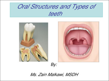
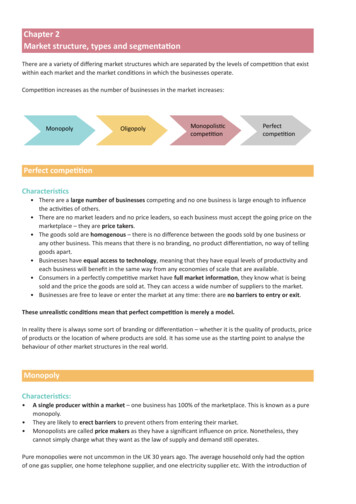
Calculation of Estimated CavitationCavitation generation in butterfly valvesCavitation is caused by low pressure areas in fluids. There are four causes of low pressure areas:Fig. 1 Butterfly valves in nearly closed position(1) Fluid is compressed, contraction flow exists, and flow velocity is increased. Then, pressure reduces.(2) Low pressure area inside vortexes at valve-outlet side.(3) Low pressure area is produced at the boundary between the fluid flowing at high velocity and objects suchas the protruding portion of the valve-moulded surface, heads of taper pins, and hubs, etc.(4) When the valve body or disc is vibrating at high frequency, the flow is disturbed and air bubbles form in thefluid.The main causes of cavitation generation in butterfly valves are (1) and (2).Thus, when the valve is nearly closed, the flow passes over the upper and lower edges of the disc as shown infigure. 1. The low pressure area can be caused when high flow velocity is created.VC (vena cont racta)Fig. 2 Orifice flowFigure 2 shows orifice flow corresponding to valve flow. The contracted part is called vena contracta. Therelation between pressure and flow rate is shown in figure 3.VCP2PvPvcFig. 3 Pressure and flow rate relationDataData-13475Flow (V)Pressure (P)When fluids flow at high velocity and pressure drops belowthe saturated vapour pressure, air bubbles are produced.They are carried away toward the valve downstream side,and then, as surrounding water recovers its originalpressure, air bubbles break instantaneously (approx. 1/1000sec) and produce a strong impact force (200 to 500 atm). Ifair bubbles break near a substance, the impact appliesgreat stress on both the outside and inside of thesubstance, and causes damage to the surface.P1
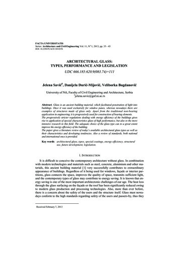
Cavitation generation process in butterfly valves and formula to estimate itThere are many stages in cavitation generation, as follows.Flow conditionsPressure conditionsExplanationFig. 4 Normal flowVCP1P2PvNormal flow means turbulent flow.In this stage, valve flow rate increasesin proportion to the square root of thedifferential pressure.PvcFig. 5 Cavitation flowP1Cavitation flow has three stages corresponding to the increase in differentialpressure.a. Incipient cavitation stageb. Critical cavitation stagec. Full cavitation stageNoise and oscillation may cause damage to the valve and downstream-sidepiping.VCP2PvPvcThis occurs when pressure on the valvedownstream side drops below the vapour pressure of the liquid. The fluidchanges from liquid to gas, bringingrapid velocity change and volume expansion. These two factors are themain causes of a flashing noise.Flashing noise is of lower level thancavitation noise because gas acts as acushion.Attention must be paid to materials ofthe valve body
Check valve Gate valve Globe valve Ball valve Valve shaped like a butterfly. Tight shut-off and can be used as a control valve. Little resistance to flow (allows smooth flow). Optimal for automated operation with a low operating torque and 90 degrees operating angle. Lightweight and compact (large diameter models are also available). For use when flow is only in one direction. Lightweight disc .