Transcription
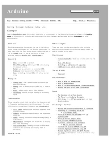
ArduinoAdvanced ProjectsCreated as a companion manual to the Toronto Public Library Arduino Kits.Arduino Advanced ProjectsCopyright 2017 Toronto Public Library. All rights reserved.Published by the Toronto Public Library.1
Table of ContentsTABLE OF CONTENTS . 2PREFACE . 3ARDUINO UNO TOUR . 5GETTING TO KNOW YOUR BREADBOARD . 6SAFETY TIPS. ERROR! BOOKMARK NOT DEFINED.INTRODUCTION. 10CONTROLLING A SERVO WITH A POTENTIOMETER . 16CREATING A 30 SECOND COUNTDOWN TIMER . 20WHAT IS AN H-BRIDGE? . 26H-BRIDGE CONTROLLED BY AN ARDUINO . 28H-BRIDGE USING POTENTIOMETER. 31RECOMMENDED RESOURCES . 372
PrefaceThank you for borrowing Toronto Public Library’s Arduino Kit. Please return this kit tothe Digital Innovation Hub from which it was borrowed.3
Borrowing Arduino Kits Arduino Kits are available to Toronto Public Library customers with a valid Teen(13-17), Adult – Under 25 (18 – 24), or Adult (25 ) library card. Holds cannot be placed on the Arduino Kits. You can only borrow one Arduino Kit at a time. Each kit can be borrowed for 21days and cannot be renewed.Fines Per Day and Maximum Fines for Arduino KitsCARD TYPEAdultAdult Under 25 (18-24)Teen (13-17) FINE AMOUNT MAXIMUM YOU WILLPER DAYBE CHARGED FOREACH LOAN PERIOD 0.35 14.00 0.15 6.00 0.15 6.00If you lose an Arduino Kit, you will be charged the purchase price of the Arduino( 50). The library does not accept a replacement Arduino or an item of equal value. If the Arduino Kit is overdue by more than 40 days, the library considers it lost. Ifyou find the kit within 6 months of paying the replacement cost you can get arefund, minus any overdue fines so please keep your receipt. Please report damaged equipment or missing parts to the Digital Innovation Hubstaff from which it was borrowed. Damaged Arduino boards and kits are subjectto replacement purchase fees.4
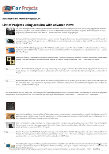
Arduino Uno TourTime Required: 10 minutesSpend a few moments looking at the diagram below and compare it to the Arduinoincluded in your kit.The Arduino has been labeled to help you learn all the different connectors and parts.5
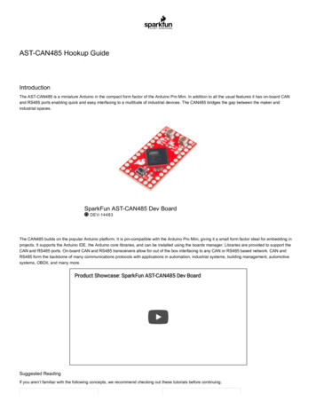
Getting to Know your BreadboardTime Required: 20 minutesVideo resources about breadboards: http://goo.gl/6HPHbgIn order for us to connect our tiny components together, we need our breadboard. Abreadboard is great for prototyping since it does not create a permanent connectionbetween components like soldering does. Everything is held together by friction whenyou insert them into those tiny holes inside your breadboard.Remember: If you have any questions, or need some extrahelp, feel free to visit a Digital Innovation Hub at theToronto Public Library for classes or assistance.Power railsAll the power rails have invisible wiresunder that run vertically.ConnectorsFive holes in each ofthe horizontal rowsare connected.What a breadboard looks like if we could see the wires under the breadboard6
The previous page is an example of how a breadboard usually looks; on the right is howa breadboard would look if we could see the wires that connect all of the holes together.Those hidden wires are used to connect all your components to each other while youprototype.Take a look at your breadboard. You may have noticed that the breadboard holes are alllabeled A to J (vertically) and from 1-30 (horizontally). This is used to indicate where toplace your components.Throughout this guide, we will be asking you to place your components in very specificholes within your breadboard. For example, we might ask you to put a wire into hole 3E.Now is the time to get familiar with the layout of your breadboard.7
Safety TipsToronto Public Library’s Arduino Kits use low voltage electricity and are not inherentlydangerous. However, safety is always important when working with electrical circuits.Please follow the safety tips and instructions in this manual at all times.Expert Tip: Always treat electronic projects as if they couldhave potentially dangerous voltages.Each project has been planned and mapped out for you. Please take the time to read andthoroughly review the project instructions from beginning to end before you begin.Ensure that wires are connected accurately and in accordance with the diagramsprovided. Not following the instructions as specified may result in personal injury ordamage to the equipment.Expert Tip: Turn off all power sources before modifying thecircuit. Keep your Arduino unplugged while you areconnecting wires and parts. Only connect it to the computerafter your setup matches the diagram provided.Keep your work surface clear when using this kit and maintain an orderly and safe workenvironment. Keep food and drinks away from the work area while working with yourArduino kit. Always unplug the Arduino when not in use. After using the kit, return allthe parts to their proper storage place.Expert Tip: Place the Arduino on a non-metal surface andrefrain from working on metallic surfaces.8
Warnings This kit is not a toy and is not appropriate for small children. Small parts may presenta choking hazard. Not for children under 3. Avoid touching the exposed end of ground and power wires when connected to theArduino. Use only the materials provided in the Arduino Kit. Do not make alterations or perform major repairs on the Arduino Kit. No soldering with the TPL Arduino kit. Do not use lithium ion batteries, they may explode when shorted Do not use on metallic surfaces, such as your Macbook. Place the Arduino on a nonmetal surface and refrain from working on the surface of your Macbook. The library is not responsible for damage to any equipment and hardware used withthe kit, including personal computers, laptops or tablets. Unplug the Arduino when not in use. Turn off/disconnect all power sources before modifying a circuit. While you’reconnecting components, keep your Arduino unplugged. Only connect it to a computeror power source after the circuit is complete.9
IntroductionAn Arduino is a microcontroller; a small, simple computer. It is designed specifically forbeginners who are new to coding and electronics. You can learn more about the Arduinoat https://www.arduino.cc/en/Guide/Introduction.There are thousands of projects you can build with an Arduino.Parts in This KitYou assembled kit includes all the parts you’ll need for the Arduino projects outlined inthis manual. When you’re done with your projects, please return the parts to theirproper slots, as indicated in this diagram, for the next person to enjoy.There are different types of Arduinos. This kit uses a blueArduino Uno board. The different parts on the Arduino arelabelled in white.10
The USB cable is used to connect the Arduino to yourcomputer.The breadboard lets you build circuits. It has a series of holeswhere you can insert wires to create circuits. The magic of abreadboard is that it’s reusable, and you don’t need to solder(permanently joining components together to form a circuitby melting metals).11
Jumper wires are used to create electric circuits and can beinserted into the breadboard.A H-Bridge IC Chip (model L293NE) is an electronicintegrated circuit chip that allows a voltage to be appliedacross a load (like a motor) in opposite directions. These areused in robotics so that you can control the direction of twomotors independently.12
DC Motor uses electricity to convert it to rotationalmechanical energy. Connect the positive and negative topower and it will spin. Reverse the positive and negative pinto reverse the power flow and it will spin the oppositedirection.Potentiometers are a manually adjustable variable resistorwith 3 terminals. Two terminals are connected to both ends ofa resistive element, and the third middle terminal connects toa sliding contact, called a wiper, moving over the resistiveelement. The position of the wiper determines the outputvoltage of the potentiometer.13
Servo Motor can be commanded to rotate to a specific angle.These motors cannot rotate continuously and only have amovement of 180 degrees.14
Part Inventory for the Advanced Kit1x Arduino1x Breadboard16x Jumper Wires1x PushbuttonThe Arduino is themicrocontroller andbrains of our project.It stores programsand processes inputsand outputs.The breadboard isused to temporarilyconnect multiplecomponents andwires together duringprototyping.Jumper wires connectthe componentscompleting a circuit.Note: The colour ofthe wires do notmatter when buildingthe projects.When you push thebutton, it completesthe circuit.1x DC Motor1x Servo MotorIt is your standardDC motor. It spinswhen you applypower.Servo motor can becommanded to rotateto a specific angle (0 180 deg).1x H-Bridge ICchipUsed to control thedirection of twomotors.1x PotentiometerCan be used to detectthe position of a knobwhen connected tothe Arduino analoginput pins.15
Controlling a Servo with a PotentiometerTime Required: 25 minutesIn this project, we will be using a potentiometer to control the movement of our servomotor. When we twist our potentiometer knob, the servo will also rotate approximatelythe same amount. Remember, it doesn’t matter what color the wires are in the diagramcompared to the ones you use.Potentiometers are like a dynamic resistor, as you twist, the resistance valuechanges (this will make the voltage change from 0-5v). These changes inresistance is what our Arduino will read and convert into a number between 0-1023.What are the pins on the includedPotentiometer?Positive PowerOutput: This pin can be connectedto an Arduino. The Arduino willread the resistance value from thepotentiometer.GroundA servo motor, is a special type of motor that can be used to rotateprecisely. There is a sensor inside the motor that keeps track of howmuch it rotates. This allows us to tell the motor to rotate by degrees and it will stop atthe correct location.16
Required Components1x Arduino1x Breadboard3x1xJumperpotentiometerwiresWiring171x Servo Motor
Diagrams for this projectWhat are the pins onour Servo Motor?Power(4.8-6v)GroundSignal (tellsServo whereto move)18
18.19.20.21.22.23.24.25.26.#include Servo.h Include the ability to use the Servo motor library (enables us to use the servo commands).const int servoPin 2;const int userInputPin A0;Servo myservo;int pos 0;void setup() {Create two constant integer variables. Variable servoPin will store the number2, and userInputPin will store the number A0.Create a new servo called myservo. We give it a name since we could control more than one servo at a time.Create an integer variable with the value of 0. This will be used to store the position the servo shouldmove to.myservo.attach(servoPin);Tell the Arduino to use (attach) the servoPin (pin #2) to the servo called “myservo”.pinMode(userInputPin, INPUT);Set the potentiometer that is connected to userInputPin (pin #A0) as anINPUT.}void loop() {Analog read the inputPin (A0), and store the value in our variablecalled pos.pos analogRead(userInputPin);pos map(pos, 0, 1023, 0, 180);Map the raw sensor data (our sensor gives us a value between 0-1023) to avalue between (0-255) and store the converted value back to the variablepos.myservo.write(pos);delay(100);}Move the servo motor (called myservo) with the calculation we didpreviously stored in the variable servoPos.Delay (pause) for 100 micoseconds. This will allow the servo motor to goto its position before being told to move again.19
Creating a 30 Second Countdown TimerTime Required: 40 minutesIn this project, we will be using a servo motor as a countdown timer. The Servo motor will rotate 3 degrees of movementfor every second for a total of 30 seconds. We have a button that is connected to the Arduino so we can restart the 30second timer when needed.Required Components1x Arduino1x Breadboard5x Jumper Wires201xPushbutton1x Servo Motor
Wiring21
CodeLine 1.Line 2.#include Servo.h Include the ability to use the Servo motor library (enables us to use the servo commands).Servo myservo;Create a new instance of a servo called myservo. We give it a name sincewe could control more than one servo at a time.Line 3.const int servoPin 9;Create a constant integer variable called servoPin with a valueof 9 (the pin the servo is using to be controlled).Line 4.const int buttonPin 2;Create a constant integer variable called buttonPin with avalue of 2 (the pin the button is connected to).Line 5.int servoPos 0;Create an integer variable called servoPos with a value of 0.This is used to store the position the servo should go.Line 6.int timerCurValue 0;Create an integer variable called timerCurValue with a valueof 0. This is used for how much time has elapsed.Line 7.const int timerSetValue 30;Create a constant integer variable called timerSetValue with avalue of 30. This is used for how long we want the timer for.22
Line 8.void setup() {Line 9.myservo.attach(servoPin);Line 10.Serial.begin(9600);Tell the Arduino to use (attach) the servoPin (pin #9) to theservo called “myservo”.Setup serial monitor at a baud rate (speed) of 9600.Set our servo (myservo) when the arduino turns on or restartsto the position at 0 degrees from the variable servoPos.Line 11.myservo.write(servoPos);Line 12.pinMode(buttonPin, INPUT PULLUP);Line 13.delay(2000);Set out button that is connected to buttonPin (pin #2) as anINPUT PULLUP.Wait two seconds before running the rest of our program. This will give our servo amoment to move to its 0 degree position if it needed to move.Line 14. }What is INPUT PULLUP?When setting an Arduino Uno pin as INPUT PULLUP thisactivates the internal 20kohm resistor in the processor. This allows usto connect a button to ground, then to the pin we want the button tobe connected to on the Arduino without using a resistor. Thishowever will reverse the logical of reading the button compared tousing INPUT. When the button is not pressed the pin will readHIGH, and when the button is pressed it will read LOW.23
Line 15. void loop() {Line 16.if(digitalRead(buttonPin) LOW) {Line 17.timerCurValue 0;Line 18.Serial.println("*** TIMER RESTARTED ***");Line 19.Read if the button is pressed. Since thebuttonPin (pin #2) is using INPUT PULLUPinstead of INPUT, the button pin will read LOWwhen pressed. When it is pressed reset the timerback to 0 and output the text “*** TIMERRESTARTED ***” in the serial monitor.}The timer starts at 0. Use the current elapsed time, multiple it by 3 andstore this calculation in the variable servoPos. This means for every secondthe servo will move 3 degrees.Line 20.servoPos timerCurValue * 3;Line 21.Serial.print("Timer: "); Serial.println(timerCurValue);Line 22.Serial.print("Position: "); Serial.println(servoPos);24Output through the serial monitorthe current elapsed timer from thevariable timerCurValue and outputthe current servo position fromthe variable servoPos.
Line 23.Serial.println();Output a line break to our serial monitor. This is only tomake it easier to read the outputs and is for aesthetics.Line 24.myservo.write(servoPos);Move the servo motor (called myservo) with the calculationwe did previously stored in the variable servoPos.Line 25.if (timerCurValue timerSetValue) {Line 26.timerCurValue timerCurValue 1;Line 27.}Line 28.delay(1000);If the current time (using our variable timerCurValue) is lessthan the set timer time (using the variable timerSetValuewhich is 30 seconds), increase the current time by one.Wait one second before looping again. This makes it take onesecond to increase the timerCurValue variable by one andmove the servo 3 degrees every second.Line 29. }25
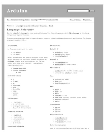
What is an H-Bridge?Time Required: 15 minutesAn H-Bridge is an electric integrated circuit that allows the ability to control up to two motors. These twomotors can be independently controlled what direction it will spin. This could allow us to create a robot forexample that could move forwards, backwards, turn left and turn right and have our Arduino programthose movements. We are just using half the chip for all the projects, most of the pins on the left-hand side ofthe chip are for controlling a second motor. See the diagram on the next page for what each pin does from the H-Bridge.26
This indented semicircle is used toindicate the top of the IC H-bridge chip5v to power the IC chip.Ground connectors for the IC chip.Only one needs to be connected.Connect thepositive andnegative pins fromthe motor to theoutput.Input pins are used to control what direction themotor will spin. When you send 5v to input 4 forexample only, then the motor will spin onedirection. When you send 5v only to input 3instead, the motor will spin the other direction.Positive voltage to power the motors5-36v up to 600mA per motor.When you send 5v to this pin, it will allow the motorconnected on the right side of the h-bridge to be enabled.27
H-Bridge Controlled by an ArduinoTime Required: 30 minutesIn this project, we will be using an H-Bridge (Model L293D) connected with our Arduino to control the motor so it canrotate clockwise or counter clockwise.Pin #9 from our Arduino must output HIGH (output 5v) to enable the h-bridge to work. Pins #11 and pin #10 is used tocontrol which direction the motor will turn. If you have pin #11 high (output 5v) the motor will spin one direction, whileif you output high on pin #9 it will spin the other direction. The motor will not turn if both pin #10 and pin #11 is high(outputting 5volts) since you are telling the h-bridge to go clockwise and counter clockwise at the same time.This project will rotate the motor clockwise for 6 seconds, stop spinning the motor for 2 seconds, rotate the motorcounterclockwise for 6 seconds, stop the motor for 2 seconds and then repeat forever.Required Components1x Arduino1x Breadboard14x JumperWires1x H-Bridge281x DC Motor
WiringThis indented semicircle is used to indicate the top of the ICH-bridge chip. Make sure you put in the h-bridge correctly.29
18.19.20.21.22.23.24.25.26.void setup() {pinMode(9, OUTPUT);pinMode(10, OUTPUT);pinMode(11, OUTPUT);Set pin #9, pin #10 and pin #11 as an outputWhen the Arduino turns on or restart, set pin #9 as HIGH (on).This pin will be used to tell the h-bridge to be enabled. We did itin the setup since we never need to turn it off laterdigitalWrite(9, HIGH);}void loop() {Set pin #10 to HIGH (on) and pin #11 to LOW(off) and then wait for 6 seconds. This will spinthe motor one directiondigitalWrite(10, HIGH);digitalWrite(11, LOW);delay(6000);Set pin #10 to LOW (off) and pin #11 to LOW (off)and then wait for 2 seconds. This will stop themotor from spinning.digitalWrite(10, LOW);digitalWrite(11, LOW);delay(2000);Set pin #10 to LOW (off) and pin #11 to HIGH(on) and then wait for 6 seconds. This will spinthe motor in the opposite direction.digitalWrite(10, LOW);digitalWrite(11, HIGH);delay(6000);Set pin #10 to LOW (off) and pin #11 to LOW (off)and then wait for 2 seconds. This will stop themotor from spinning.digitalWrite(10, LOW);digitalWrite(11, LOW);delay(2000);}30
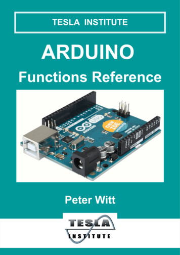
H-Bridge Using PotentiometerTime Required: 50 minutesIn this project, we will using an H-Bridge (Model L293D) with an Arduino to control the direction of the rotation of themotor based on the position of the potentiometer.Pin #9 from our Arduino will be used to control the speed of the motor attached (output 5v). Pins #11 and pin #10 is usedto control which direction the motor will turn. If you have pin #11 high (output 5v) the motor will spin one direction,while if you output high on pin #10 it will spin the other direction. The motor will not turn if both pin #10 and pin #11 ishigh (outputting 5v) since you telling the h-bridge to go clockwise and counter clockwise at the same time.The potentiometer will be used at the 12 o’clock position to stop all motor movement. If you turn the potentiometercounterclockwise, the motor will spin in that direction as well. If you turn the potentiometer clockwise the motor will spinin the direction as well. As you rotate the potentiometer more and more clockwise or counterclockwise, the motor willincrease in speed until you reached the limit of how far it can move in either direction.Required Components1x Arduino1x Breadboard12x JumperWires1xPotentiometer311x H-Bridge1x DC Motor
The above diagram above is used to illustrate the movement of the motor when you rotate the potentiometer for this project.32
WiringThisindentedsemicircleis used toindicatethe top ofthe IC Hbridgechip.33
CodeLine 1.const int motorEnPin 9;Line 2.const int motorFwdPin 10;Line 3.const int motorBkwdPin 11;Line 4.Line 5.const int potInputPin A0;Line 6.int inputValue 0;Line 7.int motorSpeed 0;Create a constant integer variable called motorFwdPin with a value of10 (the pin is used to tell the h-bridge to move the motor clockwise).Create a constant integer variable called motoBkwdPin with a value of 11(the pin is used to tell the h-bridge to move the motor counterclockwise).Create a constant integer variable called potInputPin with a value of A0(the pin is used to read the value from the potentiometer).Create an integer variable called inputValue with a value of 0 (this will beused to store the current value of our potentiometer).Create an integer variable called motorSpeed with a value of 0 (this will beused to store the current value of how fast the motor should spin).Line 8.Line 9.Create a constant integer variable called motorEnPin with a valueof 9 (the pin to enable the h-bridge to turn on).void setup() {Line 10.pinMode(motorEnPin, OUTPUT);Line 11.pinMode(motorFwdPin, OUTPUT);Line 12.pinMode(motorBkwdPin, OUTPUT);Set our pins for motorEnPin (pin #9), motorFwdPin (pin #10), motorBkwdPin(pin #11) as an OUTPUT.Line 13.Line 14.pinMode(potInputPin, INPUT);Set the potentiometer that is connected to potInputPin (pin #A0) as anINPUT.34
Line 15.Serial.begin(9600);Start serial communication when the Arduino boots. Set thecommunication speed to 9600 baud.Line 16.}Line 17.void loop() {Line 18.inputValue analogRead(potInputPin);Store the value from the potentiometer using analogReadfor the potInputPin (#A0) into the variable inputValue.Line 19.Line 20.if(inputValue 0 & inputValue 472) {Line 21.Serial.println("Clockwise");Line 22.digitalWrite(motorFwdPin, HIGH);Line 23.digitalWrite(motorBkwdPin, LOW);Line 24.motorSpeed map(inputValue, 0, 472, 255, 0);Line 25.Line 26.}else if(inputValue 552 & inputValue 1023) {Line 27.Serial.println("Counterclockwise");Line 28.digitalWrite(motorFwdPin, LOW);Line 29.digitalWrite(motorBkwdPin, HIGH);Line 30.motorSpeed map(inputValue, 552, 1023, 0, 255);Line 31.}35When the potentiometer knob input is between 0 –472, output the Serial message “Clockwise”, set themotorFwdPin to HIGH and the motorBkwdPin to LOW(this will make the H-Bridge be told to goclockwise). Store the calculated speed for the motorto spin using the variable motorSpeed. We use themap function to read the potentiometer so that whenthe knob is reading 0, the speed will be 255 (speed isa value between 0-255). When the potentiometer isreading 472, set the motor speed to 0. It will thencalculate automatically the motor speed to adjustsmoothly with the input from the potentiometer.When the potentiometer knob input is between 552– 1023, output the Serial message“Counterclockwise”, set the motorFwdPin to LOWand the motorBkwdPin to HIGH (this will make theH-Bridge be told to go counterclockwise). Store thecalculated speed for the motor to spin using thevariable motorSpeed. We use the map function toread the potentiometer so that when the knob isreading 552, the speed will be 0 (speed is a valuebetween 0-255). When the potentiometer is reading1023, set the motor speed to 255. It will thencalculate automatically the motor speed to adjustsmoothly with the input from the potentiometer.
Line 32.else {Line 33.Serial.println("Stop");Line 34.digitalWrite(motorFwdPin, LOW);Line 35.digitalWrite(motorBkwdPin, LOW);Line 36.motorSpeed 0;Line 37.}Line 38.Serial.print("Input: ");Line 39.Serial.println(inputValue);Any other value for the potentiometer knob input(which would be between 473 – 551), output theSerial message “Stop”, set the motorFwdPin toLOW and the motorBkwdPin to LOW (this willmake the H-Bridge be told to stop moving themotor). Set the speed for the motor to 0.Output the serial message “Input: ”, and thenoutput on the same line the contents of thevariable from the inputValue. Since we are usingprintln, this will create a line break after outputthe contents of that variable.Line 40.Line 41.Serial.print("Speed: ");Line 42.Serial.println(motorSpeed);Output the serial message “Speed: ”, and thenoutput on the same line the contents of thevariable from the motorSpeed. Since we are usingprintln, this will create a line break after outputthe contents of that variable.Line 43.Line 44.analogWrite(motorEnPin, motorSpeed);Line 45.Line 46.delay(100);Set the speed of the motor. This is done by usinganalogWrite to the motorEnPin (pin #9, which isconnected to the h-bridge from that pin)outputting the number stored in motorSpeed.Create a delay for 100 microseconds only so we can slowdown the serial text output to make it easier to read.36
Recommended ResourcesGet these for free at the Toronto Public LibraryWant to learn more about Arduinos? Here is a list of our favorite Toronto Public Library books and resources. Whenusing the Arduino Kit, please stick to the projects outlined in this manual. Additional projects found in the recommendedresources are for educational and entertainment purposes and are only intended for use with your personal Arduino.http://www.Arduino.ccThe official website has great tutorials and referenceresources. The website includes information on allcommands you can do for the Arduino programminglanguage and examples on how to use them.37
Learning Arduino with Peggy FisherThis beginner course consists of two hours of video andcan be accessed for free from Lynda.com (viatpl.ca/elearning with a valid Toronto Public Library card).Adventures in Arduino by Becky StewartThis book provides simple, easy-to-follow introductionsto the Arduino. It is written for 11 to 15 year olds, butwe’ve found the concepts, content, and languageengaging and applicable to adult Arduino users. Availablefrom Safari (via tpl.ca/elearning with a valid Toronto PublicLibrary card).38
Arduino for Kids (2017) by Priya Kuber, Rishi GauravBhatnagar, Vijay VaradaThis book is intended for children (ages 9 and up) andtheir parents. It includes a series of fun, easy projects thatdon’t require any knowledge of electronics. Availablefrom Safari (via tpl.ca/elearning with a valid Toronto PublicLibrary card).The Maker's Guide to the Zombie Apocalypse: DefendYour Base with Simple Circuits, Arduino, and RaspberryPi (2016) by Simon MonkNo one knows what the future holds, so we can’tdefinitively say whether or not the Arduino projects inthis book will come in handy. What we can guarantee isthat you’ll have fun learning about Arduinos in a uniqueand creative way. Available in regular print.39
Make: Drones: Teach an Arduino to Fly by DavidMcGriffyHave you ever wondered how drones work? This bookreveals drone building secrets and explains how you canget your Arduino to fly. Available in regular print and as aneBook from Safari (via tpl.ca/elearning with a valid TorontoPublic Library card).The Arduino Inventor's Guide (2017) by Derek Runbergand Brian HuangReady to move on from the Arduino kits and startworking on some more advanced projects? Why notbuild a tiny electric piano, a desktop greenhouse, or acolour-mixing night light? You’ll find ten fun Arduinoprojects in this new eBook, available from Safari (viatpl.ca/elearning with a valid Toronto Public Library card)40
Arduino Playground : Geeky Projects for theExperienced Maker (2017) by Warren AndrewsThis is the perfect resource for more advanced Arduinoprojects. One of our favourites is the Garage SentryParking Assistant, a project that can help you pull intoyour garage by setting off an alarm when you’ve gone farenough and need to hit the brakes. Available in regularprint and as an eBook from Safari (via tpl.ca/elearning with avalid Toronto Public Library card)41
Borrowing Arduino Kits Arduino Kits are available to Toronto Public Library customers with a valid Teen (13-17), Adult – Under 25 (18 – 24), or Adult (25 ) library card. Holds cannot be placed on the Arduino Kits. You can only borrow one Arduino Kit at a time. Ea