Transcription
MODEL SPECIFICATIONATLAS RESISTANCE MODIFIED PIER SYSTEM with INTEGRATEDCHANCE HELICAL TIEBACK ANCHOR and REACTION PLATE 2006, Hubbell IncorporatedAll Rights ReservedMODIFIED PIER SYSTEM WITH INTEGRATEDTIEBACK ANCHOR AND REACTION PLATEv1.0Oct/2006
THIS PAGE LEFT BLANK INTENTIONALLY
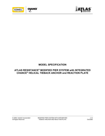
MODEL SPECIFICATIONAtlas Resistance Modified Pier System with IntegratedChance Helical Tieback Anchor and Reaction PlateAtlas Resistance Modified Piers 0.219Chance Helical Tiebacks SS125 1-1/4" RCSSS1375 1-3/8" RCSSS5 and SS150 1-1/2" RCSSS175 1-3/4" RCSGENERAL1.1 SCOPE of WORKThis work consists of furnishing all labor, tools, equipment and materials associated with the preparation and installation of theAtlas Resistance 2-Piece Modified Pier System for structural foundation support and installation of the Chance HelicalTieback System for lateral support of the proposed structure according to the specifications contained herein. The workincludes, but is not limited to the following:a.Diligent investigation of the possibleexistence and location of undergroundutilities situated at or near the area ofwork;b.Excavation and preparation of foundationsoil to grade for pier installation with anexcavation of sufficient size and depthbehind the proposed footing to permitinstallation of the Atlas Resistance 2Piece Modified Pier and insertion of theChance Helical Lead Section, and anyextension sections;c.Mounting of the hydraulic gear motor ona backhoe unit or similar auxiliarypowered equipment and the installationof the tieback anchor to the requiredtorque resistance and installation angleto achieve adequate soil cover. Removalof the hydraulic gear motor;d.Installation of the 2-Piece pier bracketincluding concrete anchors, mounting ofthe drive stand assembly and theinstallation of steel pier sections, Proofload testing the pier to designedspecifications and installation of sleevingover the pier pipe to required depth;e.Transferring the structural load to thepiers with hydraulic rams to the specifiedworking load;f.Connecting the tieback reaction plate tothe Chance Helical Tieback Anchor,securing the tieback reaction plate to theAtlas Resistance 2-Piece Modified PierBracket, conducting optional Field Loadtests on one or more Chance HelicalTieback Anchors and loading saidtiebacks to working load;g.General site clean-up.May be copied for usein bid specificationsTypical Application Using Atlas Resistance 2-Piece Modified Pierswith Integrated Chance Helical Tieback Anchors.MODIFIED PIER SYSTEM WITH INTEGRATEDTIEBACK ANCHOR AND REACTION PLATE1v1.0Oct/2006
1.2 REFERENCESa.CHANCE Civil Construction Technical Design Manual, latest version; CHANCE Civil Construction, Hubbell PowerSystems, Inc., 2006.b.Foundation Analysis and Design, Joseph E. Bowles, 4th Edition, McGraw Hill, 1988.c.Foundation Engineering, G.A. Leonards, Editor, McGraw Hill, 1962.d.American Society for Testing and Materials (ASTM) Standard Specifications, most recent versions.e.(1)ASTM A29 - Standard Specification for Steel Bars, Carbon and Alloy, Hot Wrought and Cold Finished.(2)ASTM A36 - Standard Specification for Carbon Structural Steel.(3)ASTM A53 - Standard Specification for Welded and Seamless Steel Pipe.(4)ASTM A153 - Zinc Coating (Hot Dip) on Iron and Steel Hardware.(5)ASTM A193/A193M - Alloy-Steel and Stainless Steel Bolting Materials for High Temperature Service.(6)ASTM A252 - Welded and Seamless Steel Pipe Piles.(7)ASTM A325 - Standard Specification for Structural Bolts, Steel, Heated Treated, 120/105 ksi Minimum TensileStrength.(8)ASTM A500 - Standard Specification for Cold Formed Welded and Seamless Carbon Steel Structural Tubing in Roundsand Shapes.(9)ASTM A513 - Standard Specification for Electric Resistance Welded Carbon and Alloy Steel Mechanical Tubing.(10)ASTM A536 - Standard Specifications for Ductile Iron Castings.(11)ASTM A572 - Standard Specification for High Strength Low Alloy Columbium-Vanadium Structural Steel.(12)ASTM A615 - Standard Specification for All Thread Rebar, Grade 60.(13)ASTM A656 - Hot-Rolled Structural Steel, High-Strength Alloy Plate with Improved Formability.(14)ASTM A958 - Standard Specifications for Steel Casings, Carbon, and Alloy, with Tensile Requirements, ChemicalRequirements Similar to Wrought Grades.(15)ASTM A1018 - Steel, Sheet and Strip, Heavy Thickness Coils, Hot Rolled, Carbon, Structural, High-Strength LowAlloy, Columbium or Vanadium, and High-Strength Low-Allow with Improved Formability.Society of Automotive Engineers (SAE) specifications, most recent versions.SAE J429 Mechanical and Material Requirements for Externally Threaded Fasteners.1.3 DELIVERY, STORAGE and HANDLINGAll CHANCE Civil Construction products shall be handled and transported carefully to prevent any deformation or damage.Care should be taken to prevent the accumulation of dirt, mud or other foreign matter on the steel materials. Suchaccumulation shall be completely removed prior to installation.2RESISTANCE PIER MATERIAL2.1 PIER BRACKETThe pier bracket shall be a welded assembly of 5/8" and 1/2" thick cut steel plates conforming to ASTM A36, A568 and A569.The pier bracket shall provide a bearing surface against the bottom of the footing and the vertical face of the foundation. Thepier bracket shall have an extended vertical leg that allows for securing the bracket to the footing through tabs on the sides ofthe pier bracket. The pier bracket shall have guides for installing the top pier platform.2.2 ANCHOR BOLTSEach under-footing pier bracket requires two 1/2" diameter by 5-1/2" long (minimum) steel concrete expansion bolts (fourrequired for the 4-1/2” diameter heavy duty 2-piece pier), cadmium plated with an ultimate pullout capacity of 8,000 lbs in 3,000psi concrete. Minimum embedment shall be 3-1/2". The anchor bolts shall be supplied with a flat washer and nut. The drivestand requires two (minimum) 1/2" diameter by 5-1/2" long (minimum) steel concrete expansion bolts (Hilti Kwik Bolt IIExpansion Anchors or equivalent) for temporary mounting during pier installation. Bolts are required for mounting only.May be copied for usein bid specificationsMODIFIED PIER SYSTEM WITH INTEGRATEDTIEBACK ANCHOR AND REACTION PLATE2v1.0Oct/2006
2.3 GROUT (Optional for Pier Bracket Mounting)2.3.1 PRESSURE BEARING GROUTQuick setting premixed mortar with a 4,500 psi (minimum), three day strength (Master Builder’s 713 Non-Shrink Groutor equivalent).2.3.2 FLOWABLE GROUT (Optional)Quick setting, neat cement flowable grout with a 4,000 psi (minimum) three day strength.2.4 DRIVE STAND ASSEMBLYThe drive stand assembly is a welded steel frame with a double acting hydraulic actuator capable of pressing the 42" long steelpier sections through the soil to a load bearing strata and sleeving to the design depth. The drive stand assembly is temporarilyattached to the pier bracket by means of 1" diameter by 2-3/4" long high strength locking pins and is mounted to the structurewith at least two 1/2" diameter by 5-1/2" long (minimum) steel concrete expansion bolts.2.5 PIER SECTION2.5.1AP2-2875.165 Series Pier SectionEach pier section shall be fabricated from a 2-7/8" outside diameter by 42" long mill rolled, induction heat treated steelsection with a 0.165" wall thickness. The initial section shall have a 3-1/2" outside diameter collar welded to the leadend of the pipe to assist in reducing wall friction during driving of the pier to capacity. The pier sections that follow shalleach have a coupling attached to one end and no outside collar. Steel in this section shall conform to ASTM A500Grade B.2.5.2AP2-3500.165 Series Pier SectionEach pier section shall be fabricated from a 3-1/2" outside diameter by 42" long mill rolled galvanized steel section witha 0.165" wall thickness. A triple coat corrosion protection of zinc chromate and clear polymer coating shall be provided.The initial section shall have a 4" outside diameter collar welded to the lead end of the pipe to assist in reducing wallfriction during driving of the pier to capacity. The pier sections that follow shall each have a coupling attached to oneend and no outside collar. Steel in this section shall conform to ASTM A500 Grade B.2.5.3AP2-4000.219 Series Pier SectionEach pier section shall be fabricated from a 4" outside diameter by 42" long mill rolled steel section with a 0.219" wallthickness. The initial section shall have a 4-1/2" outside diameter collar welded to the lead end of the pipe to assist inreducing wall friction during driving of the pier to capacity. The pier sections that follow shall each have a couplingattached to one end and no outside collar. Steel in this section shall conform to ASTM A500 Grade B.2.6 PIER COUPLINGThe pier coupling shall be a 6" long tubular steel section of suitable diameter to fit inside the pier section. The coupling ismechanically attached 3" inside one end of each pier section that follows the initial pier section. The remaining 3" of thecoupling extends beyond the pier section. All components conform to ASTM A513 or ASTM A500 Grade B.2.7 MODIFIED PIER SLEEVEThe sleeve is used to stiffen the segmented joints of the pier pipe. The modified sleeve pier section shall be fabricated from a42" long mill rolled tubing, 3-1/2" diameter, 0.216" wall; 4" diameter, 0.219" wall; or 4-1/2" diameter, 0.237" wall thickness. Theyield strength is 50,000 psi. The length of the modified pier sleeve that mounts last on top of the pier pipe shall have aninternal ring welded to one end. This ring provides load transfer from the structure to the pier pipe. The sleeving is suppliedone nominal diameter size greater than the pier pipe. The sleeving shall be installed in a manner that staggers the joints in thepier with the joints in the sleeving. Steel in this section shall conform to one or more of ASTM A53 or ASTM A500 Grade B.2.8 TOP PIER PLATFORMThe standard pier platform is a welded assembly consisting of an 18" long steel tube of suitable size to fit over the pier sectionthat will form the cap cylinder. The cap cylinder shall have two 10" long by 5/8" thick steel plates welded as vertical stabilizersto the sides of the steel cap cylinder. The top of the top pier platform shall be a 1" thick steel plate welded to the top of the capcylinder. All steel elements conform to ASTM A36, ASTM A500 Grade B and/or A53.May be copied for usein bid specificationsMODIFIED PIER SYSTEM WITH INTEGRATEDTIEBACK ANCHOR AND REACTION PLATE3v1.0Oct/2006
2.9 HIGH STRENGTH PIER PINSTwo 5/8" diameter by 3" long high strength, heat treated cadmium plated pier pins conforming to ASTM A29 Grade 10B21 arerequired per pier. The pins shall be quenched and tempered to HRC 36 and capable of providing 55,000 lbs of ultimate shearresistance capacity in double shear configuration.2.11 LIFT SHIMSThe lift shims shall be 7 gauge, 5/8" by 1-1/2" long cadmium plated hot rolled steel. Lift shims are used as required up to amaximum height of 4". Final adjustments shall be made with one or two 16 gauge, 5/8" by 1-1/2" long cadmium plated hotrolled steel shims. The steel shall conform to ASTM A36.2.12 WELDMENTSAll welded connections shall conform to the requirements of the American Welding Society specification "Structural WeldingCode AWS D1.1," and applicable revisions.3HELICAL TIEBACK MATERIAL3.1 HYDRAULIC GEAR MOTORHydraulic gear motors used to install Chance Helical Tieback Anchors to the desired torque are generally rated between4,500 to 12,000 ft-lb. Depending upon the soil conditions and pile configuration, different hydraulic gear motors may be used.The installation torque rating of the hydraulic gear motor shall be at least 25% higher than the planned installation torque.3.2 HELICAL TIEBACK ANCHOR for LATERAL SUPPORT3.2.1Lead SectionThe lead section consists of a round cornered square hot rolled steel lead section conforming to ASTM A29. Theshaft may be specified in sizes from 1-1/4" to 1-3/4" square, and the length of the lead section is specified from 10"long to 10 feet long as required by the application. One end of the lead section shall have a beveled pilot point to aidin starting the anchor. The other end shall have one hole to receive an integrally forged coupling or cast sleeve,depending on the shaft size. Welded to the lead section shall be one or more Grade 50 or Grade 80 hot rolled steelhelical plates with a thickness of 3/8" or 1/2" and a 3" pitch. Helical plate diameters may be specified in anycombination of equal or increasing diameters from 6" to 16".3.2.2Extension SectionA standard extension section shall be an assembly consisting of a round cornered square hot rolled steel sectionconforming to ASTM A29, an integrally forged coupling or a cast steel sleeve and mounting hardware. The shaftshall be a specified size from 1-1/4" to 1-3/4" square, and the length of the extension section specified from 36" longto 10 feet long as required by the application. One end (integrally forged couplings) or each end (cast sleeve) of theshaft shall have one hole to receive coupling attachment bolts depending on the shaft size.In higher load capacity projects or in very weak soil conditions, the standard extension section may have one or moreGrade 50 and 80 hot rolled steel helical plates with the thickness specified as either 3/8" or 1/2" and a pitch of 3"welded to the shaft. Helical plate diameters may be specified in any combination of equal or increasing diametersfrom the largest helical plate on the lead section up to 16".For Type SS5, SS150 and SS175 material, the coupling shall be formed as an integral part of the plain and helicalextension material as hot upset forged sockets. For Type SS125 and SS1375 material, the coupling shall be a caststeel sleeve conforming to ASTM A958 Grade 90/60, with two holes for connecting shaft sections together. Thesections are attached with structural grade bolts.3.2.3TransitionHelical tieback anchor thread bar shall be either a threaded stud adapter, or a combination of pre-stressed steeltendon and ductile iron or forged steel adapter, both of which are attached to the previously installed central steelshaft via an integrally forged socket or cast steel socket and coupling bolt. Tendon shall be a continuous thread steelbar of specified diameter and length depending on the application and load per ASTM A615 (Dywidag bar orWilliams All-Thread Rebar).May be copied for usein bid specificationsMODIFIED PIER SYSTEM WITH INTEGRATEDTIEBACK ANCHOR AND REACTION PLATE4v1.0Oct/2006
3.2.4Continuous Threaded RebarA continuous threaded rebar provides the attachment between the helical anchor and the tieback reaction plate. Thecontinuous threaded rebar shall be a threaded steel bar of specified diameter and length depending on theapplication and loading. Each continuous threaded rebar shall be supplied with a hex nut and bevel washer forattachment. Conforms to ASTM A615, Grade 75.3.2.5Bevel WasherA bevel washer shall be installed between the plate washer and the nut on the continuously threaded rebar. Thebevel washer helps to transfer the load between the vertical tieback reaction plate and angle of the anchor. Thestandard 15o bevel washer shall be 2" square steel, hot dip galvanized, with a 1-1/8" diameter mounting hole in thecenter to accept threaded bar.3.2.6Tieback Reaction PlateA tieback reaction plate is installed between the pier bracket and the nut and bevel washer on the end of thethreaded bar. The tieback reaction plate shall be fabricated of 3/4" thick steel plate conforming to ASTM A572, with amounting hole in the center to accept the threaded bar.4EXECUTIONThe following is intended to provide the controlling specification for the major steps undertaken in the installation of the AtlasResistance Pier System with Tieback Anchor for lateral support.WARNING!THOROUGHLY INVESTIGATE THE LOCATION OF ALL UNDERGROUND UTILITIES SITUATED AT ORNEAR THE AREA OF WORK BEFORE PROCEEDING. SERIOUS INJURY MAY RESULT FROM FAILURETO LOCATE AND AVOID CONTACT WITH UNDERGROUND UTILITIES.4.1 EXPOSURE of FOOTING or GRADE BEAMAn area shall be excavated immediately adjacent to the building foundation to expose the footing, bottom of the grade beam,stem wall or column to a width of at least 30". The excavation shall continue at least 15" vertically beneath the bottom of theconcrete and 12" under the stem wall at proposed location of the pier bracket. A chipping hammer shall be used to smoothand prepare the foundation for later mounting of the pier bracket. The vertical and bottom face of the footing, if applicable,shall, to the extent possible, be smooth and at right angles to each other. The spread footing, if present, shall be notched toallow the AP-2 Series Pier Bracket to mount directly under the bearing load of the stem wall unless directed otherwise by theengineer. DO NOT cut any reinforcing steel in the footing element without approval by the engineer. The surfaces shall besmooth, free of all dirt, debris, and loose concrete so as to provide firm bearing surfaces for the pier bracket.CAUTION!Carefully space the placements along the footing so that the structure is not over-spanned. Excessivepier spacing can cause damage to the concrete footing, stem wall and/or slab from structural overload.Ensure that the necessary existing structural considerations have been addressed before attempting tolift or stabilize a structure.4.2 INSTALLATION of the TIEBACK ANCHORThe hydraulic gear motor shall be installed on a backhoe or other suitable pier installation unit. The lead section is positionedin the excavation with the smallest helical plate nearest the soil. The opposite end is attached to the hydraulic gear motor drivehead with the appropriate drive tools, bent arm pin(s) and retaining clip(s). The lead section is usually aligned perpendicular tothe plane of the footing and installed at the specified angle down from horizontal, normally 5o to 20o. The engineer shallspecify installation angles.WARNING! UNDER NO CIRCUMSTANCES SHOULD THESE PRODUCTS AND EQUIPMENT BE USED WITHOUTPROPER TRAINING IN PROCEDURE AND KNOWLEDGE OF PRODUCT CAPACITIES. THE USE ANDOPERATION OF HYDRAULIC GEAR MOTORS CAN BE EXTREMELY HAZARDOUS WITHOUT PROPERTRAINING OF FIELD PERSONNEL. THE TORSIONAL FORCES DEVELOPED DURING INSTALLATIONCAN BE EXTREME, RESULTING IN POSSIBLE BREAKAGE OF MATERIALS AND EQUIPMENT. RAPIDTRANSFER OF THESE FORCES TO REACTION ASSEMBLIES CAN OCCUR, LEAVING NO TIME FORPERSONNEL TO AVOID CONTACT.SERIOUS BODILY INJURY, PROPERTY DAMAGE ANDPOTENTIALLY LIFE THREATENING SITUATIONS CAN ARISE FROM IMPROPER USE OF EQUIPMENTAND MATERIALS USED IN THE INSTALLATION OF THESE PRODUCTS.IF A REACTION BAR IS USED, IT MUST BE MECHANICALLY FASTENED TO A SUITABLE RESTRAINTAGAINST ROTATIONAL MOVEMENTS IN BOTH DIRECTIONS. SERIOUS INJURY AND PROPERTYDAMAGE MAY OCCUR IF AN UNMOVABLE OBJECT DOES NOT PROPERLY RESTRAIN THE REACTIONBAR IN ALL DIRECTIONS.May be copied for usein bid specificationsMODIFIED PIER SYSTEM WITH INTEGRATEDTIEBACK ANCHOR AND REACTION PLATE5v1.0Oct/2006
WARNING! DO NOT STAND ON THE REACTION BAR OR USE ANY BODY PARTS TO ATTEMPT TO RESTRAIN THEREACTION BAR. SERIOUS INJURY AND PROPERTY DAMAGE MAY OCCUR IF THE REACTION BAR ISNOT PROPERLY ATTACHED TO THE STRUCTURE OR OTHERWISE RESTRAINED BY A SUITABLEUNMOVABLE OBJECT.Additional extension sections are then installed as required until the specified design installation torque or adequate tiebackresistance is achieved at the desired depth. Driving shall cease when the final design torque is obtained through the specifieddistance. The anchor shall be driven at the design torque until the driven end of the anchor is at the proper design location toattach to the tieback reaction plate. In dense soils, a long extension section may have to be removed and a shorter oneinstalled to achieve the proper final location. The hydraulic gear motor assembly is removed after termination criteria isachieved. The installer must be mindful that the shaft of the tieback must be positioned to later connect to the underpinningpier bracket.4.3 DOCUMENTATIONThe installer shall carefully monitor the torque applied to the helical tieback anchor as it is installed. It is recommended that theinstallation torque be recorded at one foot intervals. In no case should the measurements exceed every two feet unlessdirected otherwise by the engineer. Torque may be monitored with in-line torque monitoring equipment, or with a hydraulicpressure gage that has been calibrated to the torque motor, or with equipment that measures the differential pressure acrossthe torque motor. If using hydraulic pressure to measure torque, the installer shall provide calibration data relating hydraulicpressure to torque for the selected torque motor. At the specified intervals, the installer shall record the torque in the installationlog for each helical anchor.At the conclusion of the installation, the raw field data shall be converted to a Tieback Anchor Installation Summary. A copy ofthe raw field data and the Tieback Anchor Installation Summary shall be provided to the engineer for review.4.4 INSTALLATION of the PIER BRACKETThe pier bracket shall be temporarily mounted to the drive stand assembly using 1" diameter pins and retaining clips. Theassembly is lowered into the excavation adjacent to the foundation. The pier bracket shall then be positioned and seated flushagainst the face and bottom of the footing using a hydraulic actuator or ram. The pier bracket is then fastened to the footingwith two expansion anchor bolts. If the pier bracket does not have continuous bearing support on either the vertical orhorizontal face, then pressure bearing grout shall be used to provide proper bearing prior to driving the pier. Care should beexercised to ensure that the drive stand assembly frame is aligned plumb prior to driving each pier section. A carpenter’s levelmay be used to verify the vertical alignment in both plains. The bubble shall be between the lines on the vial. It is acceptablefor the bubble to touch a line.WARNING! INCORRECT PREPARATION OF THE FOOTING MAY ALLOW THE PIER BRACKET TO ROTATE ANDSHEAR THE MOUNTING BOLTS. ROTATION OF THE PIER BRACKET CAN DAMAGE THE FOOTING,PIER, AND INSTALLATION EQUIPMENT. IN ADDITION, SERIOUS INJURY MAY OCCUR FROM FALLINGEQUIPMENT DURING PIER INSTALLATION FROM BROKEN BOLTS.Install a lateral support device between the bottom front side of the pier bracket and the vertical wall of the excavation oppositethe pier. During installation of the pier sections, maintain support against the pier bracket with the lateral support device.4.5 DRIVING and TESTING PIER SECTIONSWARNING! THE DRIVE STAND AND DRIVE CYLINDER ARE VERY HEAVY. USE PROPER LIFTING AND HANDLINGTECHNIQUES. STAY CONSTANTLY AWARE OF THE DRIVE CYLINDER’S POSITION IN THE DRIVESTAND AND THE ALIGNMENT OF THE PIER SYSTEM COMPONENTS. DO NOT LET THE CYLINDERWORK ITS WAY OUT OF POSITION. MONITOR THE FOOTING AND STRUCTURE CLOSELY FORCRACKS. DO NOT EXCEED THE HYDRAULIC CYLINDER MANUFACTURER’S WORKING PRESSUREWHEN DRIVING THE PIER SECTIONS. BEWARE OF HOT, HIGH-PRESSURE HYDRAULIC OIL. SERIOUSINJURY MAY RESULT FROM NOT FOLLOWING PROPER SAFETY TECHNIQUES.CAUTION!4.5.1CHECK TIGHTNESS OF PIER BRACKET MOUNTING BOLTS OFTEN DURING PIER SECTION ANDSLEEVE INSTALLATION. SERIOUS INJURY MAY RESULT FROM LOOSE BOLTS.Driving of Pier SectionsAll pier sections shall be continuously driven by use of the drive stand and hydraulic cylinder assembly. The initialpier section shall have the friction reduction collar on the bottom end. Additional pier sections shall be added as thepier driving operation continues. Driving of the pier sections will continue until rock or a suitable bearing stratum isreached as defined by a force equal to 1.65 times the working load specified by the engineer or until lift of thestructure is achieved, whichever is lessMay be copied for usein bid specificationsMODIFIED PIER SYSTEM WITH INTEGRATEDTIEBACK ANCHOR AND REACTION PLATE6v1.0Oct/2006
WARNING!CHECK TIGHTNESS OF PIER BRACKET MOUNTING BOLTS OFTEN DURING PIER SECTIONAND SLEEVE INSTALLATION. SERIOUS INJURY MAY RESULT FROM LOOSE BOLTS.CAUTION!DO NOT EXCEED THE HYDRAULIC CYLINDER MANUFACTURER’S WORKING PRESSUREWHEN DRIVING THE PIER SECTIONS, ESPECIALLY WITH THE RAM FULLY EXTENDED.SERIOUS INJURY MAY RESULT.If the maximum hydraulic cylinder operating pressure is reached prior to bearing stratum verification, remove thedouble acting hydraulic actuator from the drive stand assembly and replace it with a 2” x 4” x 7-1/8” supplementalblock. Install a 25 or 50 ton hydraulic ram (depending upon Proof Load force required) between the last pier sectionand the supplemental block. The hydraulic ram shall be actuated with a hand pump until bearing strata is verified asdefined by a maximum installation force of 1.65 times the designed working load.The installation force shall not exceed:AP-2-UF-2875.165M (Modified 2-7/8” Dia Pier System) 57,750 lbsAP-2-UFVL-3500.165M (Modified 3-1/2” Dia Pier Systems) 75,075 lbsAP-2-UFVL-4000.219 (4” Dia Pier Systems) 90,750 lbsor until lift of the structure is achieved, whichever is less.4.5.2Proof Load Testing (Optional)To accomplish field load testing of the Atlas Resistance Pier, CHANCE Civil Construction recommends a bearingcapacity confirmation of 1.5 times the designed working load. This operation verifies a Factor of Safety of 1.5:1 onthe field installation.Proof Loading the pier may be accomplished by either installing a 2” x 4” x 7-1/8” supplemental block in place of thehydraulic drive cylinder on the drive stand or by mounting a lift head on the pier bracket of existing work. Install a 25or 50 ton hydraulic ram (depending upon Proof Load force required) between the pier and the supplemental block orlift head. The hydraulic ram shall be actuated with a hand pump until bearing strata is verified as defined by amaximum installation force of 1.5 times the designed working load not to exceed 1.5 times the maximum publishedworking capacity.Do not exceed these maximum Proof Loads:AP-2-UF-2875.165M (Modified 2-7/8” Dia Pier System) 52,500 lbsAP-2-UFVL-3500.165M (Modified 3-1/2” Dia Pier Systems) 68,250 lbsAP-2-UFVL-4000.219 (4” Dia Pier Systems) 82,500 lbsor until lift of the structure is achieved, whichever is less.4.5.3Cutting Final Pier SectionIt is likely that the final installed pier section will have to be cut to a length suitable to provide space for installing thetop pier platform. Mark the last section of pier pipe at the proper elevation, remove the pier section from the hole andcut the pier section to the proper length using a metal cutting saw capable of a smooth cut at 90o to the length of thepier section. After cutting to length, the final pier section is replaced and the top of pier elevation checked.4.5.4Modified Pier SleeveThe modified pier sleeve is used to stiffen the pier pipe near the pier bracket. The modified pier sleeve that mountson top of the pier pipe shall have an internal ring welded to one end. This ring provides load transfer from thestructure to the pier pipe. The sleeve supplied with the modified pier system consists of one sleeve pipe with anominal diameter size greater than the pier pipe. Once the capacity of the pier is achieved and the pier pipe cut tofinal length, the drive stand assembly is used to push the pipe sleeve over the last pier section or sections. DO NOTexceed the manufacturer's rated operating capacity for the hydraulic cylinder.4.5.5Drive Equipment RemovalThe hydraulic drive cylinder is removed from the drive stand assembly. The drive stand assembly is then removedfrom the pier bracket by removing the locking pins at the pier bracket and by removing the nuts securing the drivestand assembly to the stem wall. After removing the drive stand assembly, cut off or drive the anchor bolts into thewall.May be copied for usein bid specificationsMODIFIED PIER SYSTEM WITH INTEGRATEDTIEBACK ANCHOR AND REACTION PLATE7v1.0Oct/2006
4.6 INSTALLING FLOWABLE GROUT (Optional)The engineer may require additional stiffness of the pier pipe. Usually, specifications for grouting the pier include theinstallation of a #4 steel reinforcing bar prior to introducing the grout. When the pier is installed to load bearing stratum and cutto the proper elevation, a neat cement flowable grout may be installed into the pier pipe. The grout will increase the moment ofinertia (stiffness) and corrosion resistance of the pier. The grout shall be introduced to the bottom of the pier by means of atremie tube inserted into the pier pipe. As the grout is pumped into the pier pipe the tube shall be removed as the elevation ofthe grout increases. The process shall be executed carefully so that air is not retained into the grout.4.7 INSTALLATION of the TOP PIER PLATFORMThe top pier platform shall be installed over the last installed pier section and modified pier sleeve. Align the vertical stabilizerswithin the channels on the legs of the pier bracket and tap the top pier platform until it contacts the top of the final modifiedsleeve section. A small port is provided between the cap cylinder and the platform to verify contact.4.8 LOAD TRANSFERThe load transfer operation is designed to transfer the structural support from the soil to the underpinning pier. Install the 55ton hydraulic ram as required between the pier lift head assembly and the top pier platform of the pier. Apply the specifieddesign load to the pier by pressurizing the hydraulic ram. Install the cadmium plated lift shims above the vertical stabilizerplates of the top pier platform. (Note: The 7 gauge shims shall be used for filling the space. The 16 gauge shims are onlyused for fine adjustments between the stack of shims and the bottom of the pier pin holes in the pier bracket.) Install two highstrength pier pins into the holes in the pier bracket by tapping the high strength pier pins into place. There must be a snug fit ofthe h
Piece Modified Pier and insertion of the Chance Helical Lead Section, and any extension sections; . CHANCE Civil Construction Technical Design Manual, latest version; CHANCE . Foundation Analysis and Design, Joseph E. Bowles, 4th Edition, McGraw Hill, 1988. c. Foundation Engineering, G.A. Leonards, Editor, McGraw Hill, 1962. d. American .