Transcription
THE 37 SENSOR KIT TUTORIAL1
PrefaceAbout Rees 52REES 52 was founded on 10th August, 2010 by IITians and some senior engineers fromdifferent industries, with an aim to impart technical knowledge to students across India.It has been conducting various workshops successfully across the nation in IIT-Delhi, IITMumbai, IIT-Jodhpur, IIT-Guwahati, NIT Delhi, IIIT Delhi and many other prestigiousengineering colleges and various schools.We strongly believe that complicated engineering concepts can be taught in a simplemanner using innovative methodologies and through our well-structured lectures,workshops and other practical sessions. Our sessions are planned to help students open uptheir mind and begin to look at engineering in a much broader perspective.About 37 Sensor KitThis 37 Sensor Kit is suitable for Arduino Uno, Arduino Mega 2560, Arduino Duemilanove andArduino Nano. All the code in this user guide is also compatible with these boards.Our Arduino board is fully compatible with Arduino.This kit walks you through the basics of using the Arduino board in a hands-on way. You'lllearn through building several creative projects. The kit includes a selection of the mostcommon and useful electronic components. Starting from the basics of electronics, tomore complex projects, the kit will help you control the physical world with components.In this book, we will show you circuits with both realistic illustrations and schematic diagrams.You can go to our official website www.rees52.com to download related code.If you have any questions, please send an email to info@rees52.com You can also leave amessage and share your projects on our forum.2
ContentsLESSON 1 TEMP AND HUMIDITY MODULE. 11LESSON 2 SHOCK SWITCH . 14LESSON 3 HALL MAGNETIC SENSOR MODULE . 16LESSON 4 BUTTON SWITCH. 18LESSON 5 INFRARED RECEIVER AND IR EMISSION . 20LESSON 6 PASSIVE BUZZER MODULE . 25LESSON 7 LASER MODULE . 27LESSON 8 SMD RGB MODULE AND RGB MODULE . 29LESSON 9 DS18B20 DIGITAL TEMPERATURE SENSOR MODULE . 32LESSON 10 PHOTO-INTERRUPTER MODULE. 34LESSON 11 MERCURY SWITCH . 36LESSON 12 TILT SWITCH MODULE . 38LESSON 13 REED SWITCH AND MINI REED SWITCH MODULE . 40LESSON 14 DUAL-COLOR COMMON-CATHODE LED . 43LESSON 15 KNOCK SENSOR . 45LESSON 16 DIGITAL TEMPERATURE MODULE . 47LESSON 17 FLAME SENSOR MODULE . 49LESSON 18 MENTAL TOUCH MODULE. 51LESSON 19 ANALOG TEMP MODULE. 53LESSON 20 PHOTORESISTOR MODULE. 56LESSON 21 7 COLOR FLASH LED MODULE . 59LESSON 22 HIGH-SENSITIVE VOICE SENSOR . 61LESSON 23 MAGIC LIGHT CUP MODULE. 64LESSON 24 JOYSTICK MODULE . 66LESSON 25 LINEAR HALL AND ANALOG HALL MODULE . 69LESSON 26 TRACKING MODULE AND AVOIDANCE MODULE . 72LESSON 27 ROTARY ENCODERS MODULE . 75LESSON 28 1 CHANNEL RELAY MODULE . 78LESSON 29 HEARTBEAT MODULE. 803
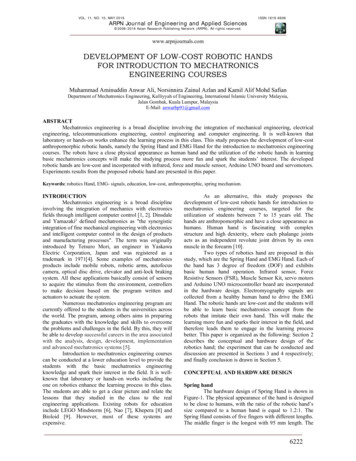
Components ListNoProduct NameQuantity1DS18B20 Module12SHOCK SWITCH13Hall Magnetic sensorModule14BUTTON SWITCH15Infrared Receiver14Picture
6IR Emission17Passive buzzer18Laser module19SMD RGB module110RGB LED module111TEMP and humiditymodule15
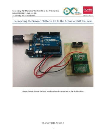
12Photo-interrupterMODULE113Mercury Switch114Tilt SWITCH MODULE115Reed switch module116Mini reed switchmodule117Mini two-color module16
18Dual-color CommonCathode LED119Knock Sensor120Digital temperaturemodule121Flame module12223MENTAL TOUCH MODULEAnalog temp module117
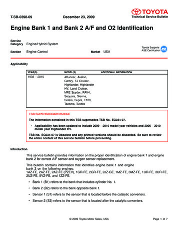
24Photo-resistor module1257 color flash module126High-sensitive VoiceSensor127Magic light cupMODULE228Joystick module129Linear hall module18
30Analog hall module131Avoidance module132Tracking module133Rotary encodersmodule134Buzzer module135Heartbeat module19
36Relay module137Small sound module1Note:After unpacking, please check that the number of components is correct and that allcomponents are in good condition.10
Lesson 1 TEMP AND HUMIDITY MODULEIntroductionIn this tutorial we will learn how to use a DHT11 Temperature and Humidity Sensor.It’s accurate enough for most projects that need to keep track of humidity andtemperature readings.Again we will be using a Library specifically designed for these sensors that will make ourcode short and easy to write.Components- 1 * Arduino Uno board- 1 * USB cable- 1 * temp and humidity module- DuPont wires(Female to Male)PrincipleExperimental ProceduresStep 1: Connect circuit as shown in the following photo:11
As you can see we only need 3 connections to the sensor, since one of the pin is not used.The connection are : Voltage, Ground and Signal which can be connected to any AnalogPin on our UNO.Step 2: Once you have the library, just go ahead and extract it to the Library folderinside your Arduino IDE software folder.Step 3: Program (please refer to the example code on the CD or official website)12
Step 3: Compile the programStep 4: Burn the program into Arduino Uno boardStep 5: Open the toll Serial Monitor, then you can see the humidity and temperature.Experimental SummaryTemp and humidity module are a very simple, very practical technology that is surprisinglyeasy to master. If you feel as though you're struggling, check out our video tutorials onwww.rees52.com or ask us questions on our forum.13
Lesson 2 SHOCK SWITCHIntroductionIn this experiment, we will learn how to use SHOCK SWITCH.Components- 1 * Arduino Uno board- 1 * USB cable- 1 * Shock Switch module- DuPont wires(Female to Male)PrincipleSHOCK SWITCH and number 13 port have the built-in LED simple circuit. To produce aSHOCK SWITCH flasher, we can use connect the digital port 13 to the built-in LED andconnect the SHOCK SWITCH S port to number 3 port of Arduino Uno board. When theSHOCK SWITCH sensing, LED twinkle light to the SHOCK SWITCH signal.Experimental ProceduresStep 1: Connect circuit as shown in the following photo:The power cord, ground wire and S port of SHOCK SWITCH connected to the Arduino boardexperiment of 5v, GND and 3 port.14
Step 2: Program (please refer to the example code on the CD or official website)Step 3: Compile the programStep 4: Burn the program into Arduino Uno boardExperimental SummarySHOCK SWITCH is a very simple, very practical technology that is surprisingly easy to master.If you feel as though you're struggling, check out our video tutorials on www.rees52.com orask us questions on our forum.15
Lesson 3 HALL MAGNETIC SENSOR MODULEIntroductionIn this experiment, we will learn how to use hall magnetic sensor module.Components- 1 * Arduino Uno board- 1 * USB cable- 1 * hall magnetic sensor module- DuPont wires(Female to Male)PrincipleHall magnetic module and number 13 port have the built-in LED simple circuit. To producea magnetic flasher, we can use connect the digital port 13 to the built-in LED and connectthe magnetic sensor S port to number 3 port of Arduino Uno board. When the hallmagnetic sensor sensing, LED twinkle light to the hall magnetic sensor signal.Experimental ProceduresStep 1: Connect circuit as shown in the following photo:The power cord, ground wire and S port of hall magnetic sensor module connected to theArduino board experiment of 5v, GND and 3 port.16
Step 2: Program (please refer to the example code on the CD or official website)Step 3: Compile the programStep 4: Burn the program into Arduino Uno boardExperimental SummaryHall magnetic sensor module is a very simple, very practical technology that is surprisinglyeasy to master. If you feel as though you're struggling, check out our video tutorials onwww.rees52.com or ask us questions on our forum.17
Lesson 4 BUTTON SWITCHIntroductionIn this experiment, we will learn how to use BUTTON SWITCH.Components- 1 * Arduino Uno board- 1 * USB cable- 1 * Button switch- DuPont wires(Female to Male)PrincipleBUTTON SWITCH and number 13 port have the built-in LED simple circuit. To produce a switchflasher, we can use connect the digital port 13 to the built-in LED and connect the BUTTONSWITCH S port to number 3 port of Arduino Uno board. When the switch sensing, LED twinklelight to the switch signal.18
Experimental ProceduresStep 1: Connect circuit as shown in the following photo:The power cord, ground wire and S port of switch module connected to the Arduino boardexperiment of 5v, GND and 3 port.Step 2: Program (please refer to the example code on the CD or official website)Step 3: Compile the programStep 4: Burn the program into Arduino Uno boardExperimental SummaryBUTTON SWITCH is a very simple, very practical technology that is surprisingly easy to master.If you feel as though you're struggling, check out our video tutorials on www.rees52.com orask us questions on our forum.19
Lesson 5 Infrared Receiver and IR EmissionIntroductionIn this experiment, we will learn how to use Infrared Receiver and IR Emission module.In fact now in our daily life they play an important role, a lot of household electricalappliances are used to this kind of device, such as air conditioning, TV, DVD, etc. Actually itis based on its wireless remote sensing and it is very convenient by using them.Components- 2 * Arduino Uno board- 2 * USB cable- 1 * Infrared Receiver- 1 * IR Emission module- DuPont wires(Female to Male)PrincipleFirstly, let's know the structure of the infrared receiving head: there are two importantelements inside the infrared receiving head, IC and PD. IC is receiving head processingcomponents, mainly composed of silicon and circuit. It is a highly integrated device. Themain function is filter, plastic, decoding, amplification, etc. PD is a photosensitive diode. Themain function is to receive the light signal.20
Below is a brief working principle diagram:Infrared emitting diode launch out the modulation signal and infrared receiver head willreceive, decode, filter and so on to regain the signal .Infrared emitting diode: keep clean and in good condition. All the parameters in theprocess of working shall not exceed the limit value (positive To the current 30 60mA,positive pulse current 0.3 1A, reverse voltage 5V, dissipation power 90mW, workingtemperature range -25 80 , and storage temperature range between 40 100 , thewelding temperature 260 ) infrared tube with a closed head should be matching use,otherwise it will influence the sensitivity.Experimental ProceduresStep 1: We first look at diagram, understand the infrared emission and receiving modulespecific connection with Arduino:21
Step 2: Connect circuit as shown in the following photo:22
Step 3: Program (please refer to the example code on the CD or official website)Step 4: Compile the programStep 5: Burn the program into Arduino Uno boardStep 6: Open the TOOL Serial Monitor, and we can see the data as below:23
Experimental SummaryThe reason that we feel infrared is a magical thing is because we can't see and touch theinfrared. But it doesn't matter, the most important thing is we can control it and make itserve us, in fact, we are even more amazing. If you feel as though you're struggling, checkout our video tutorials on www.rees52.com or ask us questions on our forum.24
Lesson 6 PASSIVE BUZZER MODULEIntroductionIn this experiment, we will learn how to use passive buzzer module.With the Arduino we can complete a lot of interactive work, commonly what we used is thelight shows. And we has been use the LED small lights in the experiment before. In thisexperiment we will make the circuit having noise. The common components that canmake sound are buzzer and speakers. Compared to the speaker, buzzer is more simple andeasy to use so in this experiment we adopts the buzzer.Components- 1 * Arduino Uno board- 1 * USB cable- 1 * Passive buzzer module- DuPont wires(Female to Male)PrincipleFunction of buzzer: Voice device of the computer, printer, copier, alarm, electronic toys,automotive electronic equipment, telephone, timer and other electronic productsThe classification of the buzzer: buzzer is mainly divided into piezoelectric buzzer andmagnetic buzzer.The circuit graphic symbol of buzzer: the letter "H" or "HA" .Experimental ProceduresStep 1: Connect circuit as shown in the following photo:25
Step 2: Program (please refer to the example code on the CD or official website)Step 3: Compile the programStep 4: Burn the program into Arduino Uno boardExperimental SummaryPassive buzzer module are a very simple, very practical technology that is surprisingly easyto master. If you feel as though you're struggling, check out our video tutorials onwww.rees52.com or ask us questions on our forum.26
Lesson 7 LASER MODULEIntroductionIn this experiment, we will learn how to use laser module.Components- 1 * Arduino Uno board- 1 * USB cable- 1 * Laser module- DuPont wires(Female to Male)PrincipleExperimental ProceduresStep 1: Connect circuit as shown in the following photo:Step 2: Program (please refer to the example code on the CD or official website)Step 3: Compile the programStep 4: Burn the program into Arduino Uno board27
Experimental SummaryLaser module are a very simple, very practical technology that is surprisingly easy to master.If you feel as though you're struggling, check out our video tutorials on www.rees52.com orask us questions on our forum.28
Lesson 8 SMD RGB MODULE AND RGB MODULEIntroductionIn this experiment, we will learn how to use SMD RGB module and RGB module.Actually, the function of SMD RGB module and RGB module are almost the same. But wecan choose the shape we like or we need.SMD RGB LED module and RGB module are made from a patch of full-color LED. Byadjusting the voltage input of R, G, B pins, we can adjust the strengt of the three primarycolors (red/blue/green) so as to implementation result of full color melange effect.Components- 1 * Arduino Uno board- 1 * USB cable- 1 * SMD RGB module- 1 * RGB module- DuPont wires(Female to Male)PrincipleRGB tricolor connect to current-limiting resistance to prevent burn outPWM adjust the mixed of three primary colors so that we can have differentcolors Working voltage: 5vThe LED drive mode: Common cathodeExperimental ProceduresStep 1: Connect circuit as shown in the following photo:29
30
Step 2: Program (please refer to the example code on the CD or official website)Step 3: Compile the programStep 4: Burn the program into Arduino Uno boardExperimental SummaryThese two module are a very simple, very practical technology that is surprisingly easy tomaster. If you feel as though you're struggling, check out our video tutorials onwww.rees52.com or ask us questions on our forum.31
Lesson 9 DS18B20 DIGITAL TEMPERATURE SENSOR MODULEIntroductionIn this experiment, we will learn how to use DS18B20 module test the environmentaltemperature and make a thermometer.Since the previous temperature sensor output is analog. So we need to add additional A/Dand D/A chip into the line transformation. More -over, the Arduino external port is not richresources and the utilization rate is not high. These cause a big challenge. So we are createthe Ds18b20 module.The new DS18B20 Temperature Sensor Module is very good solve the problem. It have thecharacteristic of the economy, unique 1-wire bus and it can fully apply the Arduino platform.Users can easily form a sensor network through using this module.Components- 1 * Arduino Uno board- 1 * USB cable- 1 * DS18B20 module- DuPont wires(Female to Male)PrincipleDS18B20 module is using a single bus. The power supply voltage range of 3.0 V to 5.5 V andno standby power supply. It can Measure temperature range for -55 degree to 125degree with accuracy of /-0.5 C.The programmable DPI of temperature sensor is From 9 to 12. temperature conversion is 12digits lattice type. maximum is 750 milliseconds. Families can be defined non-volatiletemperature alarm Settings.Each DS18B20 contains a unique serial number so that multiple ds18b20s can exist in a bus.32
Temperature sensor can detect temperature in numbers of different places at the sametime.Experimental ProceduresStep 1: Connect circuit as shown in the following photo:The power cord, ground wire and S port of DS18B20 connected to the Arduino boardexperiment of 5v, GND and 12 port.Step 2: Open PROJECT Include Library Manage Libraries install the "One Wire"and "Dallas Temperature" libraries .Step 3: Program (please refer to the example code on the CD or official website)Step 4: Compile the programStep 5: Burn the program into Arduino Uno boardStep 6: Open the TOOL Serial Monitor, and we can see the temperature. When doing theexperiment, the temperature is 27 degrees Celsius. With the hand touch the DS18B20,through the serial port we can be found there is an obvious change in temperatureExperimental SummaryDS18B20 module are a very simple, very practical technology that is surprisingly easy tomaster. If you feel as though you're struggling, check out our video tutorials onwww.rees52.com or ask us questions on our forum.33
Lesson 10 Photo-interrupter MODULEIntroductionIn this experiment, we will learn how to use Photo-interrupter MODULE.Components- 1 * Arduino Uno board- 1 * USB cable- 1 * Photo-interrupter MODULE- DuPont wires(Female to Male)PrinciplePhoto-interrupter module and number 13 port have the built-in LED simple circuit. Toproduce a switch flasher, we can use connect the digital port 13 to the built-in LED andconnect the Photo-interrupter MODULE S port to number 3 port of Arduino Uno board.When the switch sensing, LED twinkle light to the switch signal.34
Experimental ProceduresStep 1: Connect circuit as shown in the following photo:The power cord, ground wire and S port of switch module connected to the Arduino boardexperiment of 5v, GND and 3 port.Step 2: Program (please refer to the example code on the CD or official website)Step 3: Compile the programStep 4: Burn the program into Arduino Uno boardExperimental SummaryPhoto-interrupter MODULE is a very simple, very practical technology that is surprisingly easyto master. If you feel as though you're struggling, check out our video tutorials onwww.rees52.com or ask us questions on our forum.35
Lesson 11 Mercury SwitchIntroductionIn this experiment, we will learn how to use Mercury SwitchComponents- 1 * Arduino Uno board- 1 * USB cable- 1 * Mercury Switch- DuPont wires(Female to Male)PrincipleMercury Switch and number 13 port have the built-in LED simple circuit. To produce aswitch flasher, we can use connect the digital port 13 to the built-in LED and connect theMercury Switch S port to number 3 port of Arduino Uno board. When the tilt switch sensing,LED twinkle light to the switch signal.36
Experimental ProceduresStep 1: Connect circuit as shown in the following photo:The power cord, ground wire and S port of switch module connected to the Arduino boardexperiment of 5v, GND and 3 port.Step 2: Program (please refer to the example code on the CD or official website)Step 3: Compile the programStep 4: Burn the program into Arduino Uno boardExperimental SummaryMercury Switch is a very simple, very practical technology that is surprisingly easy to master.If you feel as though you're struggling, check out our video tutorials on www.rees52.com orask us questions on our forum.37
Lesson 12 Tilt SWITCH MODULEIntroductionIn this experiment, we will learn how to use Tilt SWITCH MODULE.Components- 1 * Arduino Uno board- 1 * USB cable- 1 * tilt switch module- DuPont wires(Female to Male)PrincipleTilt switch module and number 13 port have the built-in LED simple circuit. To produce aswitch flasher, we can use connect the digital port 13 to the built-in LED and connect theTilt SWITCH MODULE S port to number 3 port of Arduino Uno board. When the switch sensing,LED twinkle light to the switch signal.38
Experimental ProceduresStep 1: Connect circuit as shown in the following photo:The power cord, ground wire and S port of switch module connected to the Arduino boardexperiment of 5v, GND and 3 port.Step 2: Program (please refer to the example code on the CD or official website)Step 3: Compile the programStep 4: Burn the program into Arduino Uno boardExperimental SummaryTilt SWITCH MODULE is a very simple, very practical technology that is surprisingly easy tomaster. If you feel as though you're struggling, check out our video tutorials onwww.rees52.com or ask us questions on our forum.39
Lesson 13 REED SWITCH AND MINI REED SWITCH MODULEIntroductionIn this experiment, we will learn how to use reed switch and mini reed switch module.Components- 1 * Arduino Uno board- 1 * USB cable- 1 * reed switch- 1 * mini reed switch- DuPont wires(Female to Male)Principlereed switch and mini switch module and number 13 port have the built-in LED simple circuit.To produce a switch flasher, we can use connect the digital port 13 to the built-in LED andconnect the switch module S port to number 3 port of Arduino Uno board. When the switchsensing, LED twinkle light to the switch signal.40
Experimental ProceduresStep 1: Connect circuit as shown in the following photo:The power cord, ground wire and S port of switch module connected to the Arduino boardexperiment of 5v, GND and 3 port.41
Step 2: Program (please refer to the example code on the CD or official website)Step 3: Compile the programStep 4: Burn the program into Arduino Uno boardExperimental SummaryReed switch and mini reed switch module are very simple, very practical technology that issurprisingly easy to master. If you feel as though you're struggling, check out our videotutorials on www.rees52.com or ask us questions on our forum.42
Lesson 14 Dual-color Common-Cathode LEDIntroductionIn this experiment, we will learn how to use Dual-color Common-Cathode LED.Components- 1 * Arduino Uno board- 1 * USB cable- 1 * Dual-color Common-Cathode LED- DuPont wires(Female to Male)Experimental ProceduresStep 1: Connect circuit as shown in the following photo:43
Step 2: Program (please refer to the example code on the CD or official website)Step 3: Compile the programStep 4: Burn the program into Arduino Uno boardExperimental SummaryDual-color Common-Cathode LED is a very simple, very practical technology that issurprisingly easy to master. If you feel as though you're struggling, check out our videotutorials on www.rees52.com or ask us questions on our forum.44
IntroductionLesson 15 Knock SensorIn this experiment, we will learn how to use Knock Sensor.Components- 1 * Arduino Uno board- 1 * USB cable- 1 * Knock Sensor- DuPont wires(Female to Male)PrincipleKnock Sensor and number 13 port have the built-in LED simple circuit. To produce a switchflasher, we can use connect the digital port 13 to the built-in LED and connect the KnockSensor module S port to number 3 port of Arduino Uno board. When the switch sensing, LEDtwinkle light to the switch signal.45
Experimental ProceduresStep 1: Connect circuit as shown in the following photo:The power cord, ground wire and S port of switch module connected to the Arduino boardexperiment of 5v, GND and 3 port.Step 2: Program (please refer to the example code on the CD or official website)Step 3: Compile the programStep 4: Burn the program into Arduino Uno boardExperimental SummaryKnock Sensor is a very simple, very practical technology that is surprisingly easy to master. Ifyou feel as though you're struggling, check out our video tutorials on www.rees52.com orask us questions on our forum.46
Lesson 16 DIGITAL TEMPERATURE MODULEIntroductionIn this experiment, we will learn how to use digital temperature module.Components- 1 * Arduino Uno board- 1 * USB cable- 1 * digital temperature module- DuPont wires(Female to Male)PrincipleDigital temperature module and number 13 port have the built-in LED simple circuit. Toproduce a temperature flasher, we can use connect the digital port 13 to the built-in LEDand connect the temperature module S port to number 3 port of Arduino Uno board. Whenthe temperature sensing, LED twinkle light to the module signal.47
Experimental ProceduresStep 1: Connect circuit as shown in the following photo:The power cord, ground wire and S port of digital temperature module connected to theArduino board experiment of 5v, GND and 3 port.Step 2: Program (please refer to the example code on the CD or official website)Step 3: Compile the programStep 4: Burn the program into Arduino Uno boardExperimental SummaryDigital temperature module is a very simple, very practical technology that is surprisinglyeasy to master. If you feel as though you're struggling, check out our video tutorials onwww.rees52.com or ask us questions on our forum.48
Lesson 17 FLAME SENSOR MODULEIntroductionIn this experiment, we will learn how to use the flame sensor module.Components- 1 * Arduino Uno board- 1 * USB cable- 1 * flame sensor module- DuPont wires(Female to Male)PrincipleFlame sensor module and number 13 port have the built-in LED simple circuit. To produce aflame sensing flasher, we can use connect the digital port 13 to the built-in LED andconnect the flame sensor module S port to number 3 port of Arduino Uno board. When theflame sensor module sensing fire, LED twinkle light to the module signal.49
Experimental ProceduresStep 1: Connect circuit as shown in the following photo:The power cord, ground wire and S port of flame sensor module connected to the Arduinoboard experiment of 5v, GND and 3 port.Step 2: Program (please refer to the example code on the CD or official website)Step 3: Compile the programStep 4: Burn the program into Arduino Uno boardExperimental SummaryFlame sensor module are a very simple, very practical technology that is surprisingly easy tomaster. If you feel as though you're struggling, check out our video tutorials onwww.rees52.com or ask us questions on our forum.50
Lesson 18 MENTAL TOUCH MODULEIntroductionIn this experiment, we will learn how to use the mental touch module.Components- 1 * Arduino Uno board- 1 * USB cable- 1 * mental touch module- DuPont wires(Female to Male)PrincipleMental touch module and number 13 port have the built-in LED simple circuit. To produce amental touch sensing flasher, we can use connect the digital port 13 to the built-in LED andconnect the mental touch module S port to number 3 port of Arduino Uno board. Whenthe touch module sensing touch, LED twinkle light to the module signal.51
Experimental ProceduresStep 1: Connect circuit as shown in the following photo:The power cord, ground wire and S port of mental touch module connected to the Arduinoboard experiment of 5v, GND and 3 port.Step 2: Program (please refer to the example code on the CD or official website)Step 3: Compile the programStep 4: Burn the program in
This 37 Sensor Kit is suitable for Arduino Uno, Arduino Mega 2560, Arduino Duemilanove and Arduino Nano. All the code in this user guide is also compatible with these boards. Our Arduino board is fully compatible with Arduino. This kit walks you through the basics of using the