Transcription
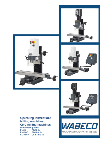
Operating instructionsMilling machinesCNC milling machineswith linear guidesF1410F1410-CCC-F1410F1410 hsF1410-C hsCC-F1410 hs
Please read before putting into operation for the first time!Every person that operates the machine, maintains or repairs it, must have read the operatinginstructions, and in particular, the safety notes prior to putting the machine into operation.Please store these documents for subsequent useOriginal version in German/translation in EnglishStatus at 09/2014Dear Customer!With the purchase of the WABECO machine you have decided in favour of a quality tool. Thismachine has been manufactured with the greatest of care and subject to precise quality controls.These operating instructions are designed to help your to use your new machine safely and correctly.For this reason, we ask you to read the appropriate notes through attentively and to take care toobserve them.After unpacking the tool, check whether any transportation damages have occurred. Complaints,whatever their nature, should be communicated immediately. Subsequent claims cannot berecognised.For all queries and replacement part orders, please always specify the machine number (see typeplate).Reprinting and reproductions of any kind, even extracts, require the written permission ofWABECODisposing of the machineThe transportation and protective packaging is made of the following materials: Corrugated card Polystyrene without Freon Polyethylene foil Timber as single-use pallet (untreated) Euro pallet (multiple use packaging)If you no longer need the items, or you do not want to reuse them, dispose of these items at theofficially recognised recycling points.The machine is manufactured in such a way that 98% of the used materials that can be recycled, forexample, steel, cast iron, aluminium and only 2% are chemical materials, e.g. cable sleeves ofelectrical cables, PCBs.If you have any difficulties in disposing of these parts properly, we would be happy to help: with prioragreement we will take back the machine in full and dispose of it. You must, however, cover the costsof sending it to us.wabeco-rs.deWalter Blombach GmbH42899 RemscheidAm Blaffertsberg 13Germany2Phone 49 (0)2191 597-0Fax 49 (0)2191 597-40E-Mail info@wabeco-remscheid.de
ContentsDeclaration of conformity F1410 LF – F1410 LF hs7Declaration of conformity F1410-C LF – F1410-C LF hs8Declaration of conformity CC-F1410 LF – CC-F1410 LF hs91.1.11.21.31.4Important safety notesIntended useImproper and incorrect useModifications to the machineSafety regulations for proper use10101010101.51.5.11.5.21.5.3Safety featuresfor all milling machinesfor milling machines with CNC control assembly and CNC milling machinesfor all CNC milling machines131313131.6Explanations oft he symbols142.2.12.2Delivery and set upTransporting the machineTransport-Lock on milling machines with ball screw spindle1415163.Putting into operation173.13.23.2.1for all milling machinesfor all CNC machinesSetting up and connecting the control computer1717174.4.1Specifications regarding the machineIdentification of the model18184.24.2.14.2.218194.2.34.2.44.2.5Noise emission declaration F1410 LF – F1410 LF hsTechnical data for F1410 LF – F1410 LF hsDimensions F1410 LF with 1.4 kW motorand trapezoidal-threaded spindleDimensions F1410 LF with 1.4 kW motor and ball screw spindleDimensions F1410 LF hs with 2.0 kW motor and trapezoidal-threaded spindleDimensions F1410 LF hs with 2.0 kW motor and ball screw spindle202122234.34.3.14.3.24.3.34.3.44.3.5Noise emission declaration F1410-C LF – F1410-C LF hsTechnical data for F1410-C LF – F1410-C LF hsDimensions F1410-C LF with 1.4 kW motor and trapezoidal-threaded spindleDimensions F1410-C LF with 1.4 kW motor and ball screw spindleDimensions F1410-C LF hs with 2.0 kW motor and trapezoidal-threaded spindleDimensions F1410-C LF hs with 2.0 kW motor and ball screw spindle2425262728294.44.4.14.4.2Noise emission declaration CC-F1410 LF – CC-F1410 LF hsTechnical data for CC-F1410 LF – CC-F1410 LF hsDimensions CC-F1410 LF with 1.4 kW motorand trapezoidal threaded spindleDimensions CC-F1410 LF with 1.4 kW motor and ball screw spindleDimensions CC-F1410 LF hs with 2.0 kW motorand trapezoidal threaded spindleDimensions CC-F1410 LF hs with 2.0 kW motor and ball screw spindle30314.4.34.4.44.4.5323334353
Contents4.54.64.7Revolution settingElectrical equipment 1.4 kW motorElectrical equipment 2.0 kW motor3637375.Achieving optimum resultsand avoiding incorrect usage376.Fitting and removing the tools397.7.17.2Installation and removal of colletsInstallationRemoval4141418.Swivelling the milling head429.Drill stroke – Depth stop4310.Feed motions of the x, y and z-axes4411.11.111.211.3Adjustment of the spindle nuts with trapezoidal-threaded 3.Lubrication of the machines4814.Operational faults and the elimination of such5015.15.115.2Operating elementsOperating elements F1410 LF with 1.4 kW motorOperating elements F1410 LF hs with 2.0 kW motor53535415.315.4Operating elements F1410-C LF with 1.4 kW motorOperating elements F1410-C LF hs with 2.0 kW motor555615.515.5.1Operating elements CC-F1410 LF with 1.4 kW motorSwitch cover on CNC operating console575815.615.6.1Operating elements CC-F1410 LF hs mit 2.0 kW motorSwitch cover on CNC operating console596016.Drawings and legends6116.1Protective hood6116.216.2.116.2.2Electronic hood with 1.4 kW motorF1410 LF – F1410-C LFCC-F1410 LF62626416.3Milling head with 1.4 kW motor6616.4Milling head wtih 2.0 kW motor6816.5Z-stand with vertical skid with trapezoidal-threaded spindle7216.616.6.116.6.2Spindle z-axis with trapezoidal-threaded spindleF1410 LF – F1410 LF hsF1410-C LF – F1410-C LF hs – CC-F1410 LF – CC-F1410 LF hs7676784
Contents16.7Lateral drive for z-axis with trapezoidal-threaded spindle8016.8Cross slide support – top slide – base plate with trapezoidal-threaded spindle8216.916.9.116.9.2Spindle x-axis with trapezoidal-threaded spindleF1410 LF – F1410 LF hsF1410-C LF – F1410-C LF hs – CC-F1410 LF – CC-F1410 LF hs86868816.1016.10.116.10.2Spindle y-axis with trapezoidal-threaded spindleF1410 LF – F1410 LF hsF1410-C LF – F1410-C LF hs – CC-F1410 LF – CC-F1410 LF hs90909216.11Z-stand with vertical skid with ball screw spindle9416.1216.12.116.12.2Spindle z-axis with ball screw spindleF1410 LF – F1410 LF hsF1410-C LF – F1410-C LF hs – CC-F1410 LF – CC-F1410 LF hs989810016.13Lateral drive for z-axis with ball screw spindle10216.14Cross slide support with ball screw spindle10416.1516.15.116.15.2Spindle x-axis with ball screw spindleF1410 LF – F1410 LF hsF1410-C LF – F1410-C LF hs – CC-F1410 LF – CC-F1410 LF hs10610610816.1616.16.116.16.2Spindle y-axis with ball screw spindleF1410 LF – F1410 LF hsF1410-C LF – F1410-C LF hs – CC-F1410 LF – CC-F1410 LF hs11011011216.1716.17.1End switch for x-axisF1410-C LF – F1410-C LF hs – CC-F1410 LF – CC-F1410 LF hs11411416.1816.18.1End switch for y-axisF1410-C LF – F1410-C LF hs – CC-F1410 LF – CC-F1410 LF hs11511516.1916.19.1End switch for z-axisF1410-C LF – F1410-C LF hs – CC-F1410 LF – CC-F1410 LF hs11611616.20Operating console for 1.4 kW motor11816.21Operating console for 2.0 kW motor12216.22Bracket arm for operating console12616.2316.23.116.23.2Industrial monitor and folio keyboardIndustrial monitor and folio keyboard for 1.4 kW motorIndustrial monitor and folio keyboard for 2.0 kW motor12813013216.24Bracket arm for industrial monitor and folio keyboard1345
cuit diagramfor motor 1.4 kWfor motor 1.4 kW and safety cabinIndustrial monitor and folio keyboard for 1.4 kW motorfor motor 2.0 kWfor motor 2.0 kW and safety cabinIndustrial monitor and folio keyboard for 2.0 kW motorMultiphase motor with end stopNC rotary tableLegend for ciruit 8.318.418.518.618.718.818.918.10Coolant system (optional)Setting up the coolant systemMounting of the coolant system to the tool cabinet (optional)Mounting of the coolant system to the tool cabinet (optional)Safety regulations for the handling of cooling lubricantFilling the coolant systemOperating the coolant system without CNC controlOperating the coolant sysem with CNC controlPositioning the segmented coolant hoseControlling the flow of coolant using the coolant shut-off valveDrawings and 19.319.419.519.619.719.8Safety cabin (optional)Setting up the safety cabinMounting of the safety cabin to the tool cabinet (optional)Safety regulations for the handling of cooling lubricantFilling the coolant system integrated in the safety cabinOperating the coolant system with CNC controlPositioning the segmented coolant hoseControlling the flow of coolant using the coolant shut-off valveDrawing and lding bracket (optional)Mounting the holding bracket to the milling machineInserting the drive unit into the holding bracketDrawing and C rotary table (optional)Clamping of work pieces on the NC rotary tableSwivelling the worm shaft in and outSetting the axial play of the NC rotary tableRemoving the NC drive unitSetting the axial play of the worm shaftSetting the axial play of the eccentric tappetDrawing and legend1551551551561571581581596
Declaration of conformityWe hereby declare, in the name of the manufacturerWalter Blombach GmbHWerkzeug- und Maschinenfabrikwith headquarters in Remscheid and NeuerburgD-42871 RemscheidD-54673 NeuerburgPostfach 12 01 61WABECO Str. 1-10Telephone: (02191) 597-0Telephone: (06564) 9697-0Fax: (02191) 597-40Fax: (06564) 9697-25that the following namedUniversal boring and milling machineType:F1410 LF - F1410 LF hsin the serial version, meets the following relevant regulations-EU Machine Directive 2006/42/ECEMC Directive 2004/108/ECEU Low Voltage Directive 2006/95/ECIn order to fulfil/implement the requirements of the directives named above, the alreadypublished and applicable standards were drawn upon:EN ISO 12100:2010DIN EN 60204-1:2006EN ISO 13128:2009Proxy for the compilation of the technical documentation is the operational head of theabove named manufacturer, Mr Christoph Schneider.D-54673 Neuerburg 2014Place and date of issueOperational head Christoph Schneider7
Declaration of conformityWe hereby declare, in the name of the manufacturerWalter Blombach GmbHWerkzeug- und Maschinenfabrikwith headquarters in Remscheid and NeuerburgD-42871 RemscheidD-54673 NeuerburgPostfach 12 01 61WABECO Str. 1-10Telephone: (02191) 597-0Telephone: (06564) 9697-0Fax: (02191) 597-40Fax: (06564) 9697-25that the following namedCNC milling machineType:F1410-C LF - F1410-C LF hsin the serial version, meets the following relevant regulations-EU Machine Directive 2006/42/ECEMC Directive 2004/108/ECEU Low Voltage Directive 2006/95/ECIn order to fulfil/implement the requirements of the directives named above, the alreadypublished and applicable standards were drawn upon:EN ISO 12100:2010DIN EN 60204-1:2006EN ISO 13128:2009Proxy for the compilation of the technical documentation is the operational head of theabove named manufacturer, Mr Christoph Schneider.D-54673 Neuerburg 2014Place and date of issueOperational head Christoph Schneider8
Declaration of conformityWe hereby declare, in the name of the manufacturerWalter Blombach GmbHWerkzeug- und Maschinenfabrikwith headquarters in Remscheid and NeuerburgD-42871 RemscheidD-54673 NeuerburgPostfach 12 01 61WABECO Str. 1-10Telephone: (02191) 597-0Telephone: (06564) 9697-0Fax: (02191) 597-40Fax: (06564) 9697-25that the following namedCNC milling machineType:CC-F1410 LF – CC-F1410 LF hsin the serial version, meets the following relevant regulations-EU Machine Directive 2006/42/ECEMC Directive 2004/108/ECEU Low Voltage Directive 2006/95/ECIn order to fulfil/implement the requirements of the directives named above, the alreadypublished and applicable standards were drawn upon:EN ISO 12100:2010DIN EN 60204-1:2006EN ISO 13128:2009Proxy for the compilation of the technical documentation is the operational head of theabove named manufacturer, Mr Christoph Schneider.D-54673 Neuerburg 2014Place and date of issueOperational head Christoph Schneider9
1.Important safety notes1.1Intended useThe milling machines described in these operating instructions are designed for the processing ofmetal, plastic and timber only.To ensure safe operation of the milling machines, the regulations set out in the chapter: "Safetyregulations" must be observed.1.2Improper and incorrect useThe milling machines described in these operating instructions have been developed andmanufactured for the purpose named above. Walter Blombach GmbH accepts no responsibility forproperty damage and personal injury caused as a result of not intended and incorrect use of themilling machines.1.3Modifications to the machineFor reasons of safety, it is forbidden for the user to make modifications of any type to the millingmachine.Walter Blombach GmbH accepts no responsibility for property damage and personal injury caused asa result of any modifications to the milling machine by the user that have not expressly beenauthorised by the company.1.4Safety regulations for proper useThe machine may represent a source of danger if it is not used correctly. For this reason, it isimportant that the following safety regulations are read attentively and observed carefully.Every person that operates the machine, maintains or repairs it, must have read the operatinginstructions, and in particular, the safety notes prior to putting the machine into operation.In order to fulfil these requirements, these operating instructions must accompany the machinethroughout its entire lifetime and be available for research.In the event that the machine changes owners, the operating instructions must thus be passed on tothe new owner along with the machine.10
1.Important safety notes1.4Safety regulations for proper use1. Only specially trained persons may operate the machine. The guarantee and warranty are voidedif damages are caused by improper operation.2. We remind you that no liability will be accepted for damages caused by not observing theseoperating instructions.3. The operator of the machine is to ensure that at least one copy of the operating instructions isstored in the immediate vicinity of the machine and available to the people who work with themachine.4. The operator is to ensure that the safety and danger notifications on the machine are observedand that the signs are kept in a legible state.5. Do not work without goggles.6. Wear close fitting clothing and, if you have long hair, wear a hair net. Do not wear loose fitting orloose items (ties, shirt sleeves, jewellery etc.).7. Gloves may not be worn.8. In the event of an emission noise level as of 80 dB (A) at the workplace, ear defenders must beworn.9. The machine may not operate without supervision.10. Secure your machine in such a way that it cannot be switched on by children. Persons who havenot been trained may not operate the machine.11. Before using the machine, make sure it is in good working condition. Pay special attention to anydamage to the grounded plug or the electrical connections. Never operate the machine with adefective, crushed or exposed cable.12. Plug the grounded plug into a suitable socket for the machine. The cable for the machine may onlybe connected to a safety socket or a connection box. Have the safety socket or connection boxchecked by an electrical specialist before hand.13. The safety socket or connection box must be close enough to the machine that the power cable isnot under strain.14. When carrying out maintenance and cleaning work, the machine must be switched off and thegrounded plug pulled out.15. Set-up work is only to be carried out with the machine switched off.16. Do not reach into the operating machine.11
1.Important safety notes1.4Safety regulations for proper use17. Always switch the machine off when you are not using it.18. Remain with the machine until it has come to a standstill.19. Only have repairs carried out by a qualified specialist! Repair work may only be carried out bypersons who are qualified for the relevant repairs and who are familiar with the appropriate healthand safety requirements.20. Protect the machine from damp21. Constantly check the machine for damages. Replace damaged parts only with original parts andhave these replaced by a specialist. The guarantee and warranty is voided if accessories andreplacement parts are use that are not designed for the machine.22. To avoid insufficient lighting, we recommend setting up a light source that provides a value of atleast 500 Lux at the tool's cutting edge.23. Do not remove the generated shavings with your hand. Use the appropriate tools (hand-heldsweeper, hook, brush).24. Tools and work pieces may never be changed when the machine is running.25. Work pieces must be secured in such a way that they are not moved from their position by therotation of the boring or milling machine.26. Work pieces must be secured by suitable fixtures e.g. prisms, machine vice etc.27. Chuck keys or similar tools may not be attached to the machine to ensure that they cannot becaught by the spindle and thrown about.12
1.Important safety notes1.5Safety features1.5.1for all milling machinesIn order to enable you to work safely with our machines, we have incorporated the following safetymechanisms. These meet the relevant European safety requirements: Protective hoodThe protective hood is secured to the machine housing and is designed to prevent touching of therotating tool spindle. The protective hood is constructed in such a way that the working height(depending on the dimensions of the work piece and tool) can be adjusted. The protective hoodcan be swivelled to enable fast exchange of tools. ON/OFF switch with under-voltage triggerThe ON/OFF switch is fitted with an under-voltage trigger, thus, in the event of a power failure, themachine does not switch itself back on automatically. This prevents risks caused by theunexpected motion of the tool spindle. Emergency off switchThe emergency off switch acts to quickly stop the machine. Overload protectionThe machine is fitted with an overload protection feature. This overload protection featureswitches the main drive motor off automatically when the machine is overloaded. The machinecan only then be switched on after a waiting period.1.5.2 for milling machines with CNC control assembly and CNC milling machinesSafety cabin (optional)In CNC mode, the door to the safety cabin must be closed in order for the milling machine to workin CNC operation.You can only work in CNC mode with the doors closed.Work carried out in conventional mode is carried out with the door open. The mode switch must beswitched to manual mode.The main spindle can be switched on when the doors are closed or open.Working in CNC mode without safety cabin may pose a serious risk to the machineoperator and cause serious accidents.1.5.3 for CNC milling machinesSwitch for operating modesThe mode switch has 3 settings (CNC mode – Idle position – Manual mode) that can only beselected with a key. After selecting the mode, the key can be removed in order to prevent aswitching of the mode type by unauthorised persons.13
1.Important safety notes1.6Explanations of the symbolsIn the event of an emission noise level as of 80dB (A) at the workplace, ear defenders must beworn.Caution:Always pull the power plug prior to anymaintenance work!Read the operating instructions prior to initialoperation or maintenance work!Caution:Dangerous electric voltage!2.Delivery and set upThe machine is packed with care at the factory.The following should be checked after delivery:1. Whether the packaging shows damages to be reported or2. Whether the machine shows transportation damages to be reported If this is the case, we ask youto communicate this information immediately. Subsequent claims cannot be recognised.The boring and milling machine must be set up on a suitable, even and firm surface. Suitablesurfaces are, for example: A tool cabinet (available optionally) A separate workbench with a level surface (spirit level) that is strong enough to carry the weight ofthe machine without bending. A steel plate with a level surface (spirit level)The machine must be screwed securely to the surface it is set up on. There are holes in the base ofthe machine that are designed for this purpose. Good working results and low-vibration operationcan only be ensured when the prerequisites for fixture as set out above are maintained.14
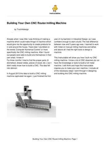
2.Delivery and set upThe place of set up should be selected in such a way that There is sufficient lighting The electrical power supply with safety socket and earth are installed close enough to the machinethat the power cable is not subject to any strain. The power cable should also be dimensioned in such a way that a multiple socket can be used, forexample, to power a coolant system.2.1Transporting the machineWe recommend three people to lift the machine, using the positions shown (1). In doing so, twopeople should hold the machine on the left and right of the upper skid, the third should hold andbalance the machine at the end of the base plate.Due to the weight of the machine it is advisable to lift the machine by crane, if this is possible. To lift,wrap suitable lashing (2) as shown around the head of the machine. Before lifting the machine, ensurethat the milling head has been moved to the upper end position to prevent damage to the machine.When lifting, pay attention to an ergonomic stance and sufficient safety!2.Delivery and set up15
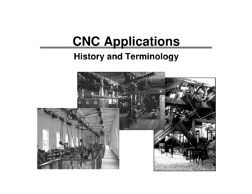
2.2Transport-Lock on milling machines with ball screw spindlesCaution – prior to machine startup the transport-lock must be removedHow to proceed:1. With the hand wheel via the Z-axis, drive the milling head a minimal distance up.2. Remove the wooden support below the milling spindle3. at least on one side, loosen the transport-lock (1)the bolts (2)4. the transport-lock (1) must be slidable without resistance5. if this is not the case, then the milling head must be moved via the hand wheel ofthe Z-axis far enough away, so that the wire cables under tension and are supportingthe weight.now the transport-lock (1) is relieved and ca be pulled off.3.16Putting into operation
3.1for all milling machines Use a dry cloth to remove the corrosion protection that was applied to all exposed parts fortransport In the event of marine impregnation of exposed parts, it is recommended you spray them with oil,allow it to work, and then remove the impregnation with a dry cloth. Once set up properly (see the section on delivery and set up) connect the grounded plug directlyto a safety socket and the 230 V 50/60 Hz (optional 110 V 60 Hz) mains power supply. Provision of sufficient coolant for the operation of a coolant system(optional) Release the axis clamps and check the individual feed spindles for easy operation Bei konventionelle Maschinen die Achsklemmungen lösen Check all electronic operating elements, for example, ON/OFF switch, emergency off switch,potentiometer etc. for functionality.3.2 for all CNC milling machinesWhen putting CNC machines into operation for the first time, always read the start-up manual.3.2.1 Setting up and connecting the control computerWhen selecting a suitable control computer, pay attention to the system prerequisites of thecontrol software. These are listed on the rear of the CD case sent with the machine.Follow the instructions in the start manual of the software to install the control software on thecomputer. The start manual can be found in the CD case of the control software included with themachine.In the next step, the software must be adapted to your machine. To do this, follow the instructions sentwith the machine which detail the editing of the parameters.When the software has been successfully installed on the control computer and all parameters havebeen adapted successfully, the control computer must be connected with the machine controller.The machine controller communicates with the computer via the serial interface (COM port). In orderto establish a connection between the machine controller and the computer, connect the end of theinterface cable that is on the machine console to the COM port of the computer.CAUTION:The axial cable of the step motors and the serial interface cable may only be plugged in orremoved when the controller is switched off. Otherwise this may lead to damage to thecontroller, the machine or the control computer.4.Specifications regarding the machine17
4.1Identification of the modelThe precise model designation of your machine can be found on the type plate attached to themachine.4.2Noise emission declarationF1410 LF – F1410 LF hsNoise emission declaration in accordance with DIN EN ISO 3744Emission values in idleF1410 LFF1410 LF hsati 50 % 66.8 dB (A 74.8 dB (A)at 100 % 66.7 dB (A) 76.4 dB (A)at 50 % 73.7 dB (A) 84.1 dB (A)at 100 % 79.1 dB (A) 80.3 dB (A)Emission noise level at the workplaceSound power levelWith an emission noise level as of 80 dB (A) at the workplaceear defenders must be worn4.18Specifications regarding the machine
4.2.1 Technical data for F1410 LF – F1410 LF hsF1410 LFF1410 LF hsWorking areasLongitudinal path, x-axis500 mmVertical path, z-axis280 mmTransverse path, y-axis200 mmDrill stroke55 mmDistance between milling machine tableand tool spindleminimum 65 mmmaximum 350 mmProtrusion of tool spindle, Z-stand185 mmMain drive motorNominal voltage230 VNominal frequencyNominal performance of the spindlemotorSpindle revolutions, infinite50/60 Hz1,4 kW2,0 kW140 - 3000 rom100 – 7500 rpmMachine accuracyConcentricity of the tool spindle0.01 mmMilling headSwivel range on both sides90 Tool spindleTool holderMK2 tightening thread M10optionalMK3 tightening thread M12SK30 DIN2080 tightening thread M12Working table700 x 180 mmNumber of groovesWidth of grooves4.312 mmSpecifications regarding the machine19
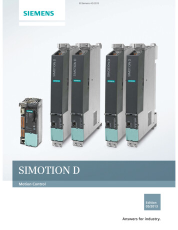
4.2.2 Dimensions F1410 LF with 1.4 kW motor and trapezoidalthreaded spindle4.20Specifications regarding the machine
4.2.3 Dimensions F1410 LF with 1.4 kW motor and ball screw spindle4.Specifications regarding the machine21
4.2.4 Dimensions F1410 LF hs with 2.0 kW motor and trapezoidalthreaded spindle22
4.Specifications regarding the machine4.2.5 Dimensions of F1410 LF hs with 2.0 kW motor and ball screw spindle4.Specifications regarding the machine23
4.3Noise emission declarationF1410-C LF – F1410-C LF hsNoise emission declaration in accordance with DIN EN ISO 3744Emission values in idleF1410-C LFF1410-C LF hsat 50 % 66.8 dB (A 74.8 dB (A)at 100 % 66.7 dB (A) 76.4 dB (A)at 50 % 73.7 dB (A) 84.1 dB (A)at 100 % 79.1 dB (A) 80.3 dB (A)Emission noise level at the workplaceSound power levelWith an emission noise level as of 80 dB (A) at the workplaceear defenders must be worn4.24Specifications regarding the machine
4.3.1 Technical data for F1410-C LF – F1410-C LF hsF1410-C LFF1410-C LF hsWorking areasLongitudinal path, x-axis500 mmVertical path, z-axis280 mmTransverse path, y-axis200 mmDrill stroke55 mmDistance between milling machine tableand tool spindleminimum 65 mmmaximum 350 mmProtrusion of tool spindle, Z-stand185 mmMain drive motorNominal voltage230 VNominal frequencyNominal performance of the spindlemotorSpindle revolutions, infinite50/60 Hz1.4 kW2.0 kW140 - 3000 rpm100 – 7500 rpmMachine accuracyConcentricity of the tool spindle0,01 mmMilling headSwivel range on both sides90 Tool spindleTool holderMK2 tightening thread M10optionalMK3 tightening thread M12SK30 DIN2080 tightening thread M12Working table700 x 180 mmNumber of groovesWidth of grooves4.312 mmSpecifications regarding the machine25
4.3.2 Dimensions F1410-C LF with 1.4 kW motor and trapezoidalthreaded spindle4.26Specifications regarding the machine
4.3.3 Dimensions F1410-C LF with 1.4 kW motor and ball screw spindle4.Specifications regarding the machine27
4.3.4 Dimensions F1410-C LF hs with 2.0 kW motor and trapezoidalthreaded spindle4.28Specifications regarding the machine
4.3.5 Dimensions F1410-C LF hs with 2.0 kW motor and ball screw spindle4.Specifications regarding the machine29
4.4Noise emission declaration CC-F1410 LF – CC-F1410 LF hsNoise emission declaration in accordance with DIN EN ISO 3744Emission values in idleCC-F1410 LFCC-F1410 LF hsat 50 % 66.8 dB (A 74.8 dB (A)at 100 % 66.7 dB (A) 76.4 dB (A)at 50 % 73.7 dB (A) 84.1 dB (A)at 100 % 79.1 dB (A) 80.3 dB (A)Emission noise level at the workplaceSound power levelWith an emission noise level as of 80 dB (A) at the workplaceear defenders must be worn4.30Specifications regarding the machine
4.4.1 Technical data for CC-F1410 LF – CC-F1410 LF hsCC-F1410 LFCC-F1410 LF hsWorking areasLongitudinal path, x-axis500 mmVertical path, z-axis280 mmTransverse path, y-axis200 mmDrill stroke55 mmDistance between milling machine tableand tool spindleminimum 65 mmmaximum 350 mmProtrusion of tool spindle, Z-stand185 mmMain drive motorNominal voltage230 VNominal frequencyNominal performance of the spindlemotorSpindle revolutions, infinite50/60 Hz1.4 kW2.0 kW140 - 3000 rpm100 – 7500 rpmMachine accuracyConcentricity of the tool spindle0.01 mmMilling headSwivel range on both sides90 Tool spindleTool holderMK2 tightening thread M10optionalMK3 tightening thread M12SK30 DIN2080 tightening thread M12700 x 180 mmWorking tableNumber of grooves3Width of grooves12 mm 0,015 mmPositioning accuracyTravel speed (fast mode)with nccad basicx and y axes30 – 600 mm/minz-axis30 – 400 mm/minwith nccad professionalx and y axes30 – 1200 mm/minz-axis30 – 800 mm/min4.Specifications regarding the machine31
4.4.2 Dimensions CC-F1410 LF with 1.4 kW motor and trapezoidalthreaded spindle4.32Specifications regarding the machine
4.4.3 Dimensions CC-F1410 LF with 1.4 kW
1.5.2 for milling machines with CNC control assembly and CNC milling machines 13 1.5.3 for all CNC milling machines 13 1.6 Explanations oft he symbols 14 2. Delivery and set up 14 2.1 Transporting the machine 15 2.2 Transport-Lock on milling machine