Transcription
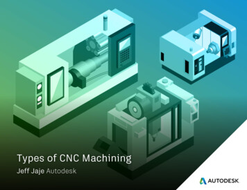
Introduction of Computer Numerical Control (CNC):The idea of numerical control started when the automation of machine tools originallyincorporated specific concepts of programmable logic. In the beginning, the first NCmachines were built back in the 1940s. Slightly more advanced machines came along inthe 1950s. These manufacturing machines were constructed based on existing toolsthat were modified with motors designed to move the controls of the machine. Thesecontrols followed specific points that were fed into the machine on punched tape.The numerical control technology moved into the 1960s and 1970s, a very familiar formof a CNC machine that most would recognize today started taking shape. Digitaltechnology then entered the fray, and automation in production processes becamemore efficient than ever. In fact, many individuals can purchase – and even design –their own homemade CNC machines. Because of how advanced computers arenowadays, it’s more common than ever to find CNC machines in all industries.What is CNC?The term “CNC” is a generic term which can be used to describe many types of device,this would include milling machines, Lathe machines, Drilling machines, plotters, CNCRouters, 3D printers, and others. CNC stands for Computer Numerically Controlled andbasically means that the physical movements of the machine are controlled byinstructions, such as co-ordinate positions that are generated using a computer.It is typically used to refer to a device which uses a rotating cutting tool/Work peacewhich moves in 2/ 3 or more axes (X, Y and Z) to cut-out or carve parts in differenttypes of materials. It is incredibly versatile and allow to cut a variety of different types ofproduct and materials. The exact abilities of a machine will vary with size, rigidity andpower.Computer skills for CNC work- One requirement common to all aspects of CNC workis how to use a computer to perform basic tasks. That may need to use a combinationof software to design and cut the parts. This will require an understanding of startingand stopping software programs, saving, copying, moving and deleting files, finding filesstored on the computer and installing programs and updates.Conventional Machines- For machining, Conventional machines are controlled bymachinists, machinists can freely control the machine axis movements, can choosespindle speed of their liking, can change tool at their will (although all these steps arecomponent material dependent, as for a harder material it has to choose a low-speedetc. but everything is controlled by the machinist.).CNC Machines:The CNC machining process are same as conventional machining process, But noteverything is in the control of CNC machinist. On a CNC machine every step toolchange/spindle-speed/axis-movement is controlled through CNC machine control. ACNC machinist can only Start/Stop/Control-tool-cutting etc. Every component gear-selection) is stored in the cncmachine-memory as a list of Instructions this is called a Part-Program or just a Program.1
CONTROLS PROGRAMMING LANGUAGE:More commonly used languages are,(i) APT (Automatically programmed tools): It is a universal part programmelanguage which can specify any component and its machining operations to becarried out on NC machines having upto 5 controlled axes. APT is a powerful andcomplex language which requires the use of a large computer and is not convenientfor simple applications. It uses the nomenclature of FORTRAN (Formulae translation)which in turn is a Universal Computer language developed by IBM.(ii) ADAPT: was the first of several alternative languages developed from APT. Itis simplified version of APT suitable for simple machines.(iii) EXAPT: (Extended Subjects of APT) is an important language developed byGermany which is made up of 3-parts.EXAPT 1 for point to point application.EXAPT 2 for turning work, power and energyEXAPT 3 for milling type works.(iv) NELAPT: is a programming language based on APT and developed bythe National Engineering Laboratory (NEL)Examples are:FEDRATFeed rateGOFWDGo forwardGOLFTGo leftTANTOTangential toHow the CNC works ?As we might already have guessed, everything that an operator would be required to dowith conventional machine tools is programmable with CNC machines. Once themachine is setup and running, a CNC machine is quite simple to keep running. In factCNC operators tend to get quite bored during lengthy production runs because there isso little to do. With some CNC machines, even the workpiece loading process has beenautomated. (We don't mean to over-simplify here. CNC operators are commonlyrequired to do other things related to the CNC operation like measuring workpieces andmaking adjustments to keep the CNC machine running good workpieces.)2
The Advantages of NC / CNC Machine Too:lThe advantages of a NC/CNC machines are quite obvious. After the initial setup, theadditional setup time is eliminated. Only one work-holding fixture is necessary becausethe transfer to other machines has been eliminated. Setup time is reduced for the samereason. Less time is needed for the change of feeds & speeds, tool selection andinsertion, and indexing of the work piece. Machining time can also be predicted becausethe human element has largely been eliminated during the machining process. A moreaccurate part is produced because of the elimination of transfer error. Can bemanufacturing the parts which are very complex in construction & having very closetolerance.The Disadvantages of NC / CNC Machine Tool:As with every system, the CNC systems too have certain disadvantages which are, (a)Higher Investment Cost- It has more sophisticated and complex technology and thistechnology cost more to buy its non CNC counterpart. So to be use these machinesmore aggressively than ordinary machines and high utilization is essential to get returnsof investment. (b) Higher maintenance cost- maintenance problem becomes more acuteand need CNC engineers with certain skill. (c) Costlier CNC Personnel- CNC machineoperations require a higher skill level than conventional operations, so skilled personnelwith particular field is required. (d) Planned support facility- The planned supports areessential i.e. Part programming, tape preparation, tool pre-setting, fundamental servicesetc.The Application of NC / CNC Machine Tool:The following areas of machining, where the CNC users can expectbenefit and improvement by applying the NC/CNC machine tools.01. To minimize the Lead time in manufacturing.02. To manufacture such parts which are very complex in constructionand it will not possible to manufacture them accurately onconventional machines due to human and machine error involved.03. To give flexibilities to machine tools to adapt such parts ofmanufacture, which are frequently subjected to change the design.04. Repetitive and precision quality parts which are to producein batch quantity. The batch may be small or medium in quantity.05. To cut down the investment cost on tooling and fixture inventory asrequired, when parts are made on a conventional machine.06. If it is an expensive parts, where mistakes in processing would be costly.07. The manufactured parts are require 100% inspection.08. Excessive metal needs to be removed.09. The manufactured parts having very close tolerance.10. Large number of operations must be performed on the part in itsmanufacturing.3
The environmental control for NC / CNC Machine Tool:Protection of machine is very important for efficient working and long life of the machine.Various types of collapsible guards, wipers and telescopic covers are used to protectthe machine guide ways, drive screws etc. As well as the following environmentalcontrol is necessary to protect the machine life.01. Dust free floor space and environment.02. Working temperature should be within control limits.03. Well air circulation.04. Space should not be congested, it should be quite open.05. Electrical power should be regulated.06. There should be proper disposal point for scrap removal.07. There should not be presence of any vibrating and noisy source nearto the machine.08. There must be proper lighting and air ventilation system.09. The machine should be operated by trained person.10. There must be provision of sufficient supply of coolant & shouldprotect from the moisture.Importance for the employees to understand CNC programming:In the past it did not seem necessary for managers, supervisors or engineers tounderstand the concepts of CNC programming. BUT NOW increasing competition,shrinking margins and high employee turnover demands that people communicatemore effectively between disciplines. 7 Easy Steps to CNC Programming. A Beginner'sGuide makes it possible for everyone, regardless of their primary job assignment, tounderstand CNC programming concepts. Engineers can more easily design for manufacture. Supervisors can be of greater support to operators. Managers/Supervisors canmore reliably measure the quality of CNC programs. Programmers using Computer Aided Manufacturing (CAM) systems can morereliably desk check programs before sending them to the shop. Managers/Supervisors can feel more confident when discussing CNC relatedissues. Managers/Supervisors can garner more respect from CNC operators andprogrammers. Well trained operators increase efficiency and profitability. Well trained operators can more easily spot programming errors. Well trained operators are less likely to scrap parts. Well trained operators are less likely to have crashes and suffer personal injury.4
Part Program for CNC Machine Tool:Part Programme is an important component of the CNC system. It is the procedure bywhich the sequence of processing steps and other related data is planned anddocumented on the CNC machine. It is a set of instructions which instruct the machinetool about the processing steps to be performed for the manufacture of a component.The shape of the manufactured components will depend on how correctly the programhas been prepared.Description of the Part Program:Every Part-program consists of multiple instruction (which tell cnc machine what to do).In the Part-program, we will see the multiple lines of instruction.Every line of part-program is called a cnc program block.Every cnc program block might consist of multiple instruction (called G-Codes/M-Codes,Co-ordinate positions, etc)So these are the instructions which tell cnc machine what to do next, when to changetool, which axis to move, how much spindle speed is required with which gear.These programs are made/written by CNC-Programmers, in the past most of programwere written by hand (even today), but nowadays multiple software are available whichease this whole process.So when the Part-program is complete those are brought to cnc machine, there aremultiple mediums and ways to transfer the program to a cnc machine, floppy disks/flashcard/networks are some of many ways used these days in workshops.Now part program is stored inside the cnc machine memory called CNC ProgramsDirectory. So now cnc machinist select the required part program for execution.Then that part program is run by cnc machinist by pressing Cycle-Start, and now thecontrol is transferred to the cnc machine control which now reads the part-program5
and instructs different parts of cnc machine to do the required operation. This waywhole the part-program instructions are executed block by block.If during this whole process anything goes wrong then cnc machinist can stop thecutting tool motion (Feed-Hold), or he can completely stop the machine (Cycle-Stop).Even cnc machinist can press Emergency-Stop-Button if anything dangerous happen orgoing to happen.If everything goes well during part-program execution then machine automatically stopsat the end of part program.Main Program: CNC main program is a series of instructions, assigned to differenttools, tool offsets and operations. Within it the various set up conditions for themachining task to be given. It is the original program, which will select for performingautomatic operation. In main program may include two or more repetitive instructions bysub-program execution command. During main program execution, sub-program areexecuted, when execution of the sub-program is finished, the sequence returns to themain program.Sub Routing Program or Sub-Program: If some repetitive features such as grooves,holes, contour profiles etc. are presenting a component and to make the part programsare proportionally longer. Simpler ways of achieving such repetitions are provided bythe facility of repetitive programming techniques are called Sub Program or a branch oran extension of the main program. In fact it is a independent program with all thefeatures of a usual part program are stored in the memory under separate programnumber and may nested with another sub-program, whenever a particular feature isrequired within the program, the associated subroutine is called for execution withrepeated any number of times with in the main program. Use of sub programmingtechniques significantly reduces the length of resulting part program, shortens the timeand reduces the computer memory space.Manual Programming: Manual programming or On machine programming (with out acomputer) has been the most common method of preparing a part program. In manualprogramming all mathematical calculations are done by hand and all instructions areentered manually by control key board entry directly at the machine. It requires the totalinvolvement of the CNC programmer and offers virtually unlimited freedom in thedevelopment of the program structure. The latest CNC controls make manualprogramming much easier than before by using fixed or repetitive machining cycles,variable type programming, graphic tool motion simulation, standard mathematical inputand other time saving features. There are some disadvantages associated with manualprogramming. The most common is the length of time required to develop a fullfunctioning program. The manual calculations, verifications and other related activitiesare very time consuming. The complex jobs are very difficult to calculate all the dataand may come a large percentage of errors and a lack of tool path verification.6
Computerized Programming:Difficult or complex jobs will benefit from a computerized programming system.Technologies such as Computer Aided Design (CAD) and Computer AidedManufacturing (CAM) have been a strong part of this process. Program can generatewith in a shortest time by using an inexpensive desktop or a laptop computer. Thebenefits offered by this technology are too significant just design, drafting, Tool pathgeneration, Tool path verification and programming. Programmed data can betransferred to the CNC machine via a cable or other data transferable method.Direct numerical control (DNC) / Distributed numerical control:DNC is a common manufacturing term for networking CNC machine tools. On someCNC machine controllers, the available memory is too small to contain the machiningprogram (for example machining complex surfaces), so in this case the program isstored in a separate computer and sent directly to the machine. If the computer isconnected to a number of machines it can distribute programs to different machines asrequired. Usually, the manufacturer of the control provides suitable DNC software.Means DNC is(1) “A system connecting a set of numerically controlled machines to a commonmemory for part program or machine program storage with provision for on-demanddistribution of data to machines.”(2) Several NC machines are directly controlled by a computer, eliminating substantialhardware from the individual controller of each machine tool. The part-program isdownloaded to the machines directly (thus omitting the tape reader) from the computermemory.CNC Program Blocks:Every cnc program is a sequence of many cnc program blocks which are writtentogether to form of a complete tool-path for one or many tools.This tool-path tells cnc machines how a cnc machinist wants his component to bemachined.Every single cnc program block adds / alters / modifies some useful information to a cncprogram.7
Definition of a Sequence Block or Block Format:The basic unit of a part program input to the control is called Block. Each block is aindividual line contains adequate information for the machine to perform the functions ora movement. Block on turn are made up of words and each words consists of a numberof characters. Just like the word is used a single instruction and the block is a multipleinstruction to the CNC system and it is terminated by the End of Block character.It may consists are .01. Optional block skip ( / )02. Sequence Number ( N )03. Preparatory Functions ( G )04. Dimensional Information’s ( X ,Y , Z, u, v, w, A, B, C, R, I, J, K etc. )05. Decimal Point ( . )06. Feed rate ( F )07. Spindle Speed ( S )08. Tool Number ( T )09. Tool offset function ( D )10. Miscellaneous function ( M )11. End of Block ( EOB )01. Sequence Number ( N - word ) The first word in every block is the sequencenumber, it is used to identify the block, written as N1, N2, N3 etc.02. Preparatory Function ( G - word ) The preparatory word prepare the control unitto execute the instructions, that enables the controller to interpret the data which followsand precedes the coordinate words. i.e. G01 is used to prepare the controller for linearinterpolation.03. Coordinates or Dimensional Information’s ( X-,Y-,Z-, etc. words ) Thesewords give final coordinate positions of the motion with Preparatory command. LikeG00/G01 X50 Y45 Z200 . G02/G03 X60 Y55 R10.04. Decimal Point ( . ) In some systems, decimal point is not coded but the controlsystem automatically provides a decimal point at a pre-set position. But in such casesleading zeros may have to be given to the program, e.g. X 7.09 will be given as X 709005. Feed Function ( F - word ) The feed function is used to specify the feed rate inthe machining operation. The feed rate is expressed either in millimeter or inch. perminute (mm or inch./min) and millimeter or inch. per revolution (mm or inch./rev). Theappropriate preparatory command should be specified.06. Spindle Speed Function ( S - word ) The speed function is used to specify thespeed rate of main spindle in the machining operation. The spindle speed is specifiedeither in revolution per minute (rev/min) and meters or feet per minute (m or ft./min).The appropriate preparatory command should be specified.8
07. Tool Selection Function ( T - word ) The T- word in the part program specifieswhich tool is to be used in the operation and the tool offsets. It is also needed formachines with programmable tool turret or automatic tool changer (ATC), because thereis tool pocket with distinct tool number.i.e.T01, T02, T23 etc.08. Tool offset function ( D - word ) The D- word is denote for tool diameter offsetnumber. It is counted for cutter radius compensation.09. Miscellaneous function ( M - word ) The miscellaneous function word is used tospecify certain machine functions, which do not relate to the dimensional movements ofthe machine. It may be Spindle ON/OFF, Coolant ON/OFF, etc.10. End of Block ( EOB ) The EOB symbol identifies the end of instruction block orline.Axis Identification in NC/CNC machines:Most of the machine have two or more slide ways, disposed at right angles to eachother, along which the slides are displaced and each slide is fitted with a control system.For the purpose of giving commands to the control system the axis have to be identified.The basis of axis identification is the 3-dimensional Cartesian coordinate system andthe three axis of movement are identified as X, Y and Z axis. Rotary movements aboutX, Y and Z axis are designated as A , B and C respectively.X - axis: The X-axis of motion is always horizontal and is always parallel to the workholding surface. In turning center diameter axis or cross slide motion is X- axis.Y - axis: The Y-axis of motion is always at the rightangles to both the X-axis and Z- axis. On verticalmachining centers, the Y-axis is perpendicular tothe column and on horizontal machining centre, theY-axis is perpendicular to the earth.9
Z - axis: The Z-axis of motion is always the axis of the main spindle of the machine. Onvertical machining centers, the Z-axis is vertical and on horizontal machining centre andturning centers, the Z-axis is horizontal. Positive Z movement ( Z ) is in the directionthat increases the perpendicular distance between the work piece and the cutting tool.Important Note For axis motion of the machine tool, may moves the work piece ormay moves the cutting tool, it is depends upon the machine tool feature. Theprogrammer may confuse with the direction of motion. So in all cases the part programaxis motion should be written assuming that the cutting tool moves. Also it is the cutterpath which is defined in the program, In case of milling program the axis motion andcutter position should be programmed with respect to centre of the cutter.CNC Lathe Machine Axis XZCNC Milling Machine Axis XYZRotary axis: The rotary motion about the X, Y and Z axis are identified by A, B, Crespectively. Rotary motion with parallel to X axis is ‘A’ axis, parallel to Y axis is ‘B’ axisand parallel to Z axis is ‘C’ axis.10
Planes in NC/CNC machine: A plane is a surface in which a straight line joining anytwo of its points will completely lie on the surface. Machining in planes, means the pathof cutting tool is a combination of straight lines and arcs and the tool motion in one ortwo axes always takes place in a plane, designated by two axes i.e. XY, YZ andXZ.Machine Zero The machine Zero point is at the origin of the coordinate measuringsystem of the machine. The machine zero point is fixed and can not be sifted. Themachine zero point is also called Home Position of the machine.Work Zero Work piece zero or datum may be defined as a point, line or surface onthe component drawing to which all the dimensions referenced. For writing the partprogram, the programmer should know the relationship between the work piece zerocoordinate and machine zero coordinate.Coordinate system or Dimensioning system:Address in a CNC program that relate to the tool position at a given moment are calledthe Coordinate Word. It is always take a dimensional value. Dimensional values have aspecified point of reference. There are two type of coordinate system or dimensioningsystem are used to define and control the position of the tool in relation to the workpiece. Each system has its own applications and the both system may be usedindependently or may mixed with in a part program according to the machiningrequirements of the components. (i) Absolute coordinate system and (ii) Incrementalcoordinate system.Absolute Coordinate system In the absolute programming mode, all dimensionsare measured from the point of origin. The origin is the program reference point also11
known as program zero or datum. The actual motion of the machine is the differencebetween the current absolute position of the tool and the previous absolute position.The algebraic sign ( ) plus or (-) minus refer to the quadrant of rectangular coordinates,not the direction of motion.The main advantage of absolute programming is the ease of modification by theprogrammer or by the CNC operator. A change of one dimension does not affect anyother dimensions in the program.Incremental Coordinate system In the incremental programming mode, also calleda relative mode, all program dimensions are measured as departure distances into aspecified direction ( equivalent to the ‘distance-to-go’ on the control system). Means thecoordinate position of a point are measured with reference to the previous point i.e. thepoint at which the cutting tool is positioned and is taken as zero or datum point forcalculating coordinates of the next point to which movement is to be made. The actualmotion of the machine is current position of the tool to the next position. The algebraicsign ( ) plus or (-) minus is specify the direction of the tool motion not refer to thequadrant of rectangular coordinates. The main advantage of incremental programmingis their portability between individual sections of a program. It is mostly used whendeveloping subprograms or repeating an equal distance. It is not ease of modification bythe programmer or by the CNC operator. A change of one dimension will effect on otherdimensions in the program.12
Preparatory Codes or Geom. setting & movement Commands:The program address ‘G’ identifies a preparatory command or Geometrical setting andmovement command, often called the G code. This address has one and only objectivethat is to preset or to prepare the control system to a certain desired condition, or to acertain mode or a state of operation.G-code is a language in which people tell computerized machine Tools what to makeand how to make it. The "what" and "how" are mostly defined by instructions on whereto move to, how fast to move, and through what path to move. The most commonsituation is that a cutting tool is moved according to these instructions, cutting awayexcess material to leave only the finished workpiece. Non-cutting tools, such as coldforming tools, burnishing tools, or measuring probes, are also sometimes involved.Theletter "G" Generally it is a code telling the machine tool what type of action to perform,such as:1. Rapid move (transport the tool through space to the place where it isneeded for cutting; do this as quickly as possible)2. Controlled feed move in a straight line or arc line.3. Series of controlled feed moves that would result in a hole beingbored, a workpiece cut (routed) to a specific dimension, or a profile(contour) shape added to the edge of a workpiece.4. Controlled Speed.5. Set tool information such as work offset, Tool Dia. and Length offset.6. Switch coordinate systems7. Input system mm/inch.8. Type of Compensation9. Information of Work offset, etc.G- FunctionG-codesDescriptionG00Rapid Traverse with m/c feedG01Linear Interpolation with given feedG02Circular Interpolation Clock WiseG03Circular Interpolation Counter Clock WiseG04Dwell ( waiting time )G17Plane Selection XYG18Plane Selection XZG19Plane Selection YZGroup01000213
G20Input in InchG21Input in MillimeterG28Machine Zero return/Return to reference pointG40Tool Nose Radius Compensation CancelG41Tool Nose Radius Compensation in LeftG42Tool Nose Radius Compensation in RightG43Tool Length Compensation PositiveG44Tool Length Compensation NegativeG49Tool Length Compensation CancelG50Coordinate system setting/max. Speed SettingG54Work Coordinate system Selection P1G55Work Coordinate system Selection P2G56Work Coordinate system Selection P3G57Work Coordinate system Selection P4G58Work Coordinate system Selection P5G59Work Coordinate system Selection P6G80Canned cycle cancelG82Spot Drilling cycleG83Peck Drilling cycleG84Tapping CycleG85Boring CycleG90Absolute DimensioningG91Incremental DimensioningG94Feed Rate mm. or inch. per minute settingG95Feed Rate mm. or inch. per revolution settingG96Constant Cutting Speed SettingG97Constant RPM Setting/ CCS Cancel06000708001203051714
Modal Code Many program words are modal. The word modal is based on the word‘mode’ and means that the specific command remains in this mode after it has beenused in the program once. It can only be canceled by another modal command of thesame group. In same group may tell one is cancel command for other. For example:G90- Absolute Dimensioning/ G91- Incremental Dimensioning, G00- Rapid Traverse/G01- Linear Interpolation, G20- Input in Inch/ G21- Input in Metric, G94- Feed per min/G95- Feed per revolution, G96- Constant cutting speed/ G97- Constant RPM, etc.Non-Modal Code Whose functionality starts and ends in the same block. Means the‘G’ code is effective only in the block in which it is specified, is called Non-Modal Codeor One Shot Code. For example:- G04- Dwell, G28- Machine zero return, Certainmachining instructions, such as tool change, pallet change, indexing table, etc.Interpolation Functions G00 ( Positioning ) The G00 command moves a tool tothe position in the work piece systemspecified with an absolute or incrementalcommand at a rapid traverse rate. In theabsolute command coordinate value of theend point and in the incremental commandthe distance the tool moves is to beprogrammed. i.e. G00 XP YP ZP ; It moveseach axis at its max speed until its vector isachieved. Shorter vector usually finishes first.the programmer needs toconsiderdepending on what obstacles are nearby, toavoid a crash. G00 XP YP ; (Tool movesto XY position with Rapid motion or with machine feed rate. )G01 (Linear interpolation) The tool moves along a straight line to the position inthe work piece system, specified with an absolute or incremental command within theshortest possible time at the feed rate specified in F. In the absolute commandcoordinate value of the end point and in the incremental command the distance the toolmoves is to be programmed. The feed rate specified in F is effective until a new value isspecified. It need not be specified for each block. If the F code is not commanded, thefeed rate is regarded as zero. i.e. G01 XP YP ZP F- ; The G01 command can notfunctioned without specified Feed. G01 XP YP F ;( Tool moves along a line to the XYposition with the feed specified in F ).G02/ G03 ( Circular interpolation Positioning CW/ CCW ) The tool moves along an arc line to the position in the work piece system, specified withan absolute or incremental command in the positive or negative direction with thespecified arc center by addresses I, J and K or radius R at the feed rate specified in F.15
In the absolute command coordinate value of the end point and in the incrementalcommand the distance the tool moves is to be progra
with conventional machine tools is programmable with CNC machines. Once the machine is setup and running, a CNC machine is quite simple to keep running. In fact CNC operators tend to get quite bored during lengthy production runs because there is so little to do. With some CNC machine