Transcription
Installation InstructionsSLC 5/03 and SLC 5/04 ProcessorsFirmware/Operating System UpgradeIntroductionEnclosed in this package is a firmware/operating system upgrade foryour SLC 5/03 or SLC 5/04 processor. Take anti-static precautionswhen upgrading the firmware.ATTENTION!The Flash EPROMs are electrostatic sensitive devices.Do not handle without proper groundingprecautions. Do not install PROM with powerapplied to the SLC 5/03 or SLC 5/04 processor.If you upgrade an SLC 5/03 or SLC 5/04 processor, you receiveanomaly fixes as well as added functionality. During the upgrade, theladder logic program inside the processor is erased. Therefore, thefirst step in upgrading the firmware/operating system is to save theprocessor’s ladder logic program.This product is CE compliant for all applicable directives whenproduct or packaging is marked.Installation ProcedureFollow these instructions carefully. Refer to page 3 for componentplacement information.1. Save the current user program to your hard drive using yourprogramming software, to a memory module, or to a 1747-PSDProgram Storage Device.IMPORTANTThe user program is cleared as part of thefirmware/operating system upgrade process.You must restore your program after loadingthe upgrade. Also, all communication ports arereturned to the default parameters.2. Remove the communication cable between the processor andyour programming terminal.1Publication 1747-IN007C-EN-P - October 2002
2SLC 5/03 and SLC 5/04 Processors Firmware/Operating System Upgrade3. Remove power from the chassis containing the processor.ATTENTION!Do not remove the processor from the SLC 500chassis until all power is removed from the SLC500 power supply.4. Remove the processor from the chassis.5. Plug the firmware/operating system upgrade pack into thememory module socket.6. Move the operating system write-protect jumper (J4) to theunprotected, or program, position.IMPORTANTPublication 1747-IN007C-EN-P - October 2002Jumper J4, located in the bottom right corner ofthe motherboard, provides write protection fromany download of a new operating system. The“out of the box” position of this jumper is“PROTECT,” or write protect. Without thejumper, the processors are write protected.
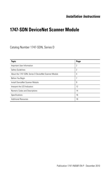
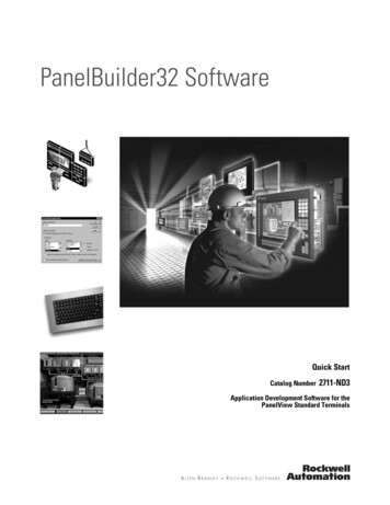
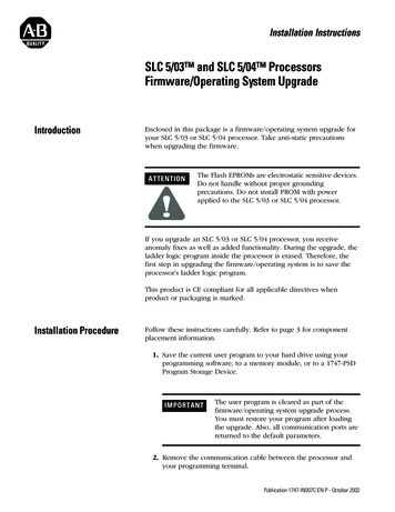
SLC 5/03 and SLC 5/04 Processors Firmware/Operating System Upgrade3Figure 1 Component Placement InformationCatalog and SerialNumber LabelPlace the firmwareupgrade label here.SLC 500PLACE FRN UPGRADE LABEL HEREPROCESSOR UNITOPERATING SYSTEM INFOSERFAC OS #CATSERFRNCURRENT REQUIREMENTS:PROTECTWHITEREDSERIAL NO.PROC. REV. -BATTERYThe SLC 5/03 and SLC 5/04processors are protected from thefirmware download when jumper J4is in this position:13PROGRAMJ4ULcLISTED IND. CONT. EQ.FOR HAZ. LOC. A196SA1A @ 5 VDC200mA @ 24 VDCRCLASS 1, GROUPS A, B, C AND D, DIV. 2OPERATING TEMPERATURE CODE T3CMADE IN USADaughter BoardORThe SLC 5/03 and SLC 5/04processors accept the firmwaredownload when jumper J4 is in thisposition:Mother BoardFirmwareUpgrade/MemoryModule SocketJumper J47. Firmly seat the processor back into the chassis.8. Apply power to the chassis containing the processor whilewatching the LED display. All the LEDs should turn on and thenturn off. The download process of the firmware takes up to 2.5minutes. While the download is in progress, the RUN and FLTLEDs remain off. The other four LEDs – RS232, DH485 (DH onthe SLC 5/04), FORCE, and BATT – turn on and off in a walkingbit sequence. If the download is successful, these four LEDsremain on together. If the FLT LED turns on and a combinationof LEDs flash on and off indicating an error condition, refer tothe troubleshooting information on page 4.9. After completing the download, remove power from the chassiscontaining the processor.ATTENTION!Do not remove the processor from the SLC 500chassis until all power is removed from the SLC500 power supply.10. Remove the processor from the chassis.11. Carefully remove the firmware upgrade pack and place it in theanti-static packaging it was shipped in.Publication 1747-IN007C-EN-P - October 2002
4SLC 5/03 and SLC 5/04 Processors Firmware/Operating System Upgrade12. Move the operating system write-protect jumper (J4) back to theprotected position (see diagram on page 3).IMPORTANTFailure to return the J4 jumper to the protectedposition results in an error (0x3D Hex) on thepower cycle following the download of a validprogram to the processor. This error conditionprevents the module from going to run andcauses Channel 0 communication settings toreturn to their defaults. To properly clear theerror, place the J4 jumper in the protectedposition, and then re-download a valid userprogram to the processor.13. Apply the enclosed firmware upgrade label to the processornameplate.14. Firmly seat the processor back into the chassis.15. Attach the communication cable between the processor andyour programming terminal.16. Apply power to the chassis containing the processor whilewatching the LED display. All the LEDs should flash on and thenturn off except for the FLT LED which should remainingflashing. If the FLT LED turns on and a combination of LEDsflash on and off indicating an error condition, refer to thetroubleshooting information in this document.17. Restore your program.Identifying ProcessorErrors While DownloadingFirmwareThe download process of the firmware/operating system takes up to2.5 minutes. While the download is in progress, the RUN and FLTLEDs remain off. The other four LEDs – RS232, DH485 (DH on theSLC 5/04), FORCE, and BATT – turn on and off in a walking bitsequence. If the download is successful, these four LEDs remain ontogether.If the download is not successful, the FLT LED turns on and acombination of LEDs flash on and off indicating an error condition.The following LED diagrams and tables provide information regardingerror messages, possible cause(s) for the error, and recommendedaction(s) to take to resolve the error.Publication 1747-IN007C-EN-P - October 2002
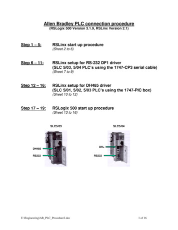
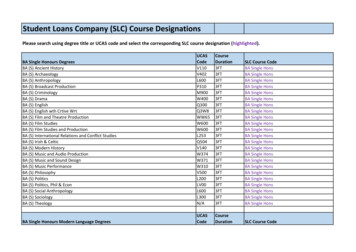
SLC 5/03 and SLC 5/04 Processors Firmware/Operating System Upgrade5If the LED’s indicate:(1)POWERThe FollowingError ExistsProbable CauseRecommended ActionRUNFORCEFLTDH485BATTRS232Fatal HardwareErrorMajor hardware failure due tonoise, improper grounding, orpoor power source.Cycle power and see if the errorrepeats itself. If the error clears,you should be able to downloadthe firmware. If the error persists,contact your RockwellAutomation representative.Probable CauseRecommended ActionRUNFORCEThe FollowingError ExistsFLTDH485BATTRS232CorruptedOperatingSystem MemoryModuleThe operating system on theFlash EPROM is corrupt.Cycle power and see if the errorrepeats itself. If the error persists,either contact your RockwellAutomation representative for anew operating system upgradecartridge, or download the oldoperating system, if available.The FollowingError ExistsProbable CauseRecommended ActionFlash EPROMFailureThe processor flash EPROM iscorrupt.Cycle power and see if the errorrepeats itself. If the error clears,you should be able to downloadthe firmware. If the error persists,contact your RockwellAutomation representative.The FollowingError ExistsProbable CauseRecommended ActionCorrupt orMissingOperatingSystemThe operating system is missingor has been corrupted.Cycle power. If error clears, youshould be able to download thefirmware. If the error persists,contact your RockwellAutomation representative for anew operating system.If the LED’s indicate:(1)POWERIf the LED’s indicate:(1)POWERRUNFORCEFLTDH485BATTRS232If the LED’s indicate:(1)POWERRUNFORCEFLTDH485BATTRS232Refer to the following key to determine the status of the LED indicators:Indicates the LED is OFF.Indicates the LED is ON.(1) The DH485 LED on the SLC 5/03 processor is labeled DH on the SLC 5/04 processor.Publication 1747-IN007C-EN-P - October 2002
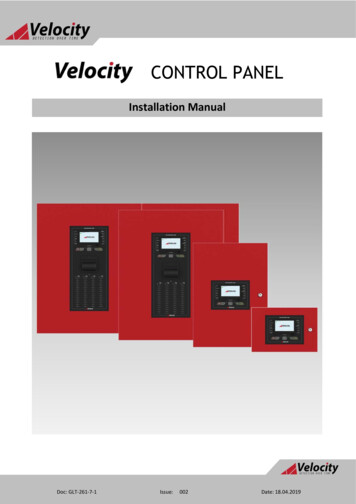
6SLC 5/03 and SLC 5/04 Processors Firmware/Operating System UpgradeIf the LED’s indicate:(1)POWERRUNFORCEFLTDH485BATTRS232The FollowingError ExistsProbable CauseRecommended ActionDownloadableOperatingSystem FailureFailure during transmission ofdownloadable operating system.Download the operating system.The FollowingError ExistsProbable CauseRecommended ActionIf the LED’s iblePlatformThe upgrade of the operatingsystem is incompatible with theprocessor hardware.Use an operating system that iscompatible with your processorhardware.Probable CauseRecommended ActionRUNFORCEThe FollowingError ExistsFLTDH485BATTRS232Memory WriteProtectedAn attempt was made todownload the operating systemonto write-protected memory.Change the J4 jumper of theSLC 5/03 and SLC 5/04processors to the programposition.If the LED’s indicate:(1)POWERRefer to the following key to determine the status of the LED indicators:Indicates the LED is OFF.Indicates the LED is ON.(1) The DH485 LED on the SLC 5/03 processor is labeled DH on the SLC 5/04 processor.Publication 1747-IN007C-EN-P - October 2002
SLC 5/03 and SLC 5/04 Processors Firmware/Operating System Upgrade7If the LED’s indicate:(1)POWERRUNFORCEFLTDH485BATTRS232The FollowingError ExistsProbable CauseRecommended ActionNVRAM errorMajor hardware failure due tonoise, improper grounding, orpoor power source.Cycle power and see if the errorrepeats itself. If the error clears,you should be able to downloadthe firmware. If the error persists,contact your RockwellAutomation representative.The FollowingError ExistsProbable CauseRecommended ActionHardwareWatchdogTime-outMajor hardware failure due tonoise, improper grounding, orpoor power source.Cycle power and see if the errorrepeats itself. If the error clears,you should be able to downloadthe firmware. If the error persists,contact your RockwellAutomation representative.If the LED’s indicate:(1)POWERRUNFORCEFLTDH485BATTRS232Refer to the following key to determine the status of the LED indicators:Indicates the LED is OFF.Indicates the LED is ON.(1) The DH485 LED on the SLC 5/03 processor is labeled DH on the SLC 5/04 processor.Publication 1747-IN007C-EN-P - October 2002
Rockwell AutomationSupportRockwell Automation provides technical information on the Web to assistyou in using its products. At http://support.rockwellautomation.com, you canfind technical manuals, a knowledge base of FAQs, technical and applicationnotes, sample code and links to software service packs, and a MySupportfeature that you can customize to make the best use of these tools.For an additional level of technical phone support for installation,configuration, and troubleshooting, we offer TechConnect Support programs.For more information, contact your local distributor or Rockwell Automationrepresentative, or visit http://support.rockwellautomation.com.Installation AssistanceIf you experience a problem with a hardware module within the first 24hours of installation, please review the information that's contained in thismanual. You can also contact a special Customer Support number for initialhelp in getting your module up and running.United States1.440.646.3223Monday – Friday, 8am – 5pm ESTOutside UnitedStatesPlease contact your local Rockwell Automation representative for anytechnical support issues.New Product Satisfaction ReturnRockwell tests all of its products to ensure that they are fully operationalwhen shipped from the manufacturing facility. However, if your product isnot functioning, it may need to be returned.Publication 1747-IN007C-EN-P - October 2002 21Supersedes Publication 1747-IN007B-EN-P - October 2001United StatesContact your distributor. You must provide a Customer Support casenumber (see phone number above to obtain one) to your distributor inorder to complete the return process.Outside UnitedStatesPlease contact your local Rockwell Automation representative forreturn procedure.PN 40071-093-01(3)Copyright 2007 Rockwell Automation, Inc. All rights reserved. Printed in Singapore.
8. Apply power to the chassis containing the processor while watching the LED display. All the LEDs should turn on and then turn off. The download process of the firmware takes up to 2.5 minutes. While the download is in progress, the RUN and FLT LEDs remain off. The other four LEDs - RS232, DH485 (DH on the SLC 5/04), FORCE, and BATT - turn on.