Transcription
instructablesBuilding Your Own CNC Router/milling Machineby TrochilidesignAlready when I was little I was thinking of making amachine which could make things! A machine whichwould give me the opportunity to create products forin and around the house. Years later I stumbled onthe words 'Computer Numerical Control' or morespecifically the CNC milling machine. After I foundout people were able to build one themselves in theirown shed, I knew it!For three months I tried to find the proper parts (Adremeltool, drawer slides, pieces of wood, etc.), but Ididn't really know how to build a CNC. The idea fellinto oblivion.In August 2013 the idea to build a CNC millingmachine captivated me again. I just finished the firstyear of my bachelor in Industrial Design, so I wasconfident enough to start a build. The real differencebetween now and 5 years ago was, I learned to workwith metal on manual milling machines and lathesand above all I had the right tools to design amachine.This Instructable will show you how I built my CNCmilling machine. I know a lot of CNC dreamers do nothave the knowledge or tools to build a full metalmachine. I still think and hope this Instructableinspires you to make your own machine. I include allof the necessary steps I went through in designingand building this CNC milling machine.Building Your Own CNC Router/milling Machine: Page 1
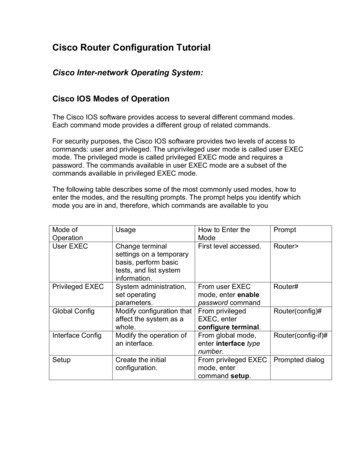
Step 1: The Design and CAD ModelIt all started with a proper design, in my case a fewsketches to get a good feeling for the dimensions andshape. Quickly after the sketching phase came theCAD model. I created my model in SolidWorks. If youplan to design your own machine I recommend aparametric CAD-modeling tool. Your machine willmost likely have a lot of parts which have to fittogether neatly, sometimes with some strangedimensions (for example pre-ordered parts). After allthe parts were modeled, technical drawings weremade. I used these drawings to machine all of thecustom parts on the manual lathe and millingmachine.Since I'm a lover of good designed tools, I tried tomake maintenance and the possibility to adjust thingson the machine as easy as possible. Bearings couldhave been integrated in the machine, but I chose toplace them in separate bearing blocks (in case itneeds to be replaced in the future). Keeping yourmachine clean is very important too, so guiderails areall accessible (in case of the x-axis by detachingsome cover plates)Step 2: The FrameThe frame provides the machine a rigid basis, notonly to place it in your workshop but also for workingon. To the frame the gantry will be mounted on slidingrails and later on a work surface. It also houses thestepper motor and spindle for the x-axis. I constructedmy frame from 2 Maytec 40x80mm profiles, 2endplates (both 10 mm thick aluminium), 4 cornerpieces and a square structural piece.All of the profiles are sawed right-angled andafterward milled exactly square. With the cornerpieces a heavy (well relatively lightweight; it's allaluminium) frame was bolted together. The squareframe made from the smaller profiles were mountedwith 4 milled blocks (aluminium) on the inside of theMaytec profiles.Since the frame sits beneath the worksurface dustcould fall down on the guiderails (you want to keepthem clean, more about that in step 5). To preventthis, dust covers were made and mounted around theguiderails. A angular profile mounted with brassmilled t-nuts onto the may tech frame and 2mmaluminium plates mounted in the milled pockets onthe endplates.On both endplates bearing blocks are mounted for thespindle. They were hand milled and lathed to the righttolerances. On the front endplate mounting slots forthe stepper motor were milledBuilding Your Own CNC Router/milling Machine: Page 2
3645232111. Milled parts for dust covers2. Linear guide rails; discussed in step 53. Maytech Aluminium 40x80mm extruded profile4. 40x40mm aluminium profile for a rigid structure5. 90degree angle pieces6. Lots of T-slots for T-nuts. Mounting things to the frame is just peanuts1. Dustcovers mounted2. Linear guiderails with the runner blocks slided on3. The square structure assembled and mounted in theframe11. DustcoverBuilding Your Own CNC Router/milling Machine: Page 3
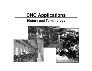
Step 3: The GantryThe gantry is the bridge between the x-axis guiderailsand supports your milling motor above the workpiece.The higher you make it, the thicker the workpiece canbe. There is however a disadvantage of high gantries.They work as levers on the guiderails and on theother hand the side plates tend to bend more easilyby making them longer.Most of the work I planned to do with the CNCinvolved milling aluminium parts. An average vise forthe machine would be 60 mm high. Since the thickestblocks of aluminium easily available for me would be60 mm high as well, I chose to space between thework surface and the piece of metal, which could hitthe workpiece first, to be 125 mm. This gave me astarting point for the side plates. Since I wanted thecenter of an end mill hovering over the center of therunnigblocks (from the machines side view), the sideplates had to be placed at an angle. Solidworkshelped me to convert all of the measurements into thefinal parts. Because of all the complex dimensions Idecided to mill these parts on an industrial CNC mill,this also gave me the opportunity to round all of thecorners (would have been very hard to mill on amanual mill).formed out of an 5mm thick U-profile. It is mountedbetween the side plate with the help of two simplemounting blocks. On the inside the U-profile housesthe y-axis spindle. Which is again supported by thesame bearing blocks used for the x-axis. They aremounted on the outside of the side plates.Beneath the main frame a plate was mounted on theunderside of the gantry's side plates, giving amounting point for the x-axis spindle nut.The part which supports the y-axis guiderails is11. Sideplates of the gantry; they were CNC milled on an industrial machine.Building Your Own CNC Router/milling Machine: Page 4
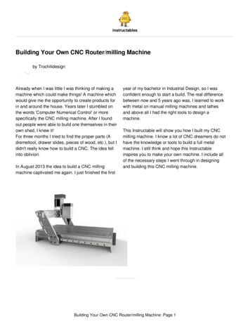
Step 4: Last MovementThe last movement is what I call theStepermotorhousing for the z-axis (plus the z-axisitself of course). It is constructed out of a frontplatemounted on the y-axis linear guiderails, 2reinforcement plates, a motor mount and a backplate.On the front plate 2 linear guiderails were mounted forthe z-axis onto which the Mountingplate for the millingmotor was placed with the runner blocks.The motor mount has the bearing for the z-axisspindle fitted into it. So I didn't use a bearing block forthis spindle and is only supported on the top. he lowerend is floating behind the mounting plate for themilling motor. The spindle nut for the Z-axis wasdirectly bolted on the mounting plate for the millingmotor.The backplate provides a spot for the y-axis spindlenut to be mounted; it is mounted on the inside.All of the custom mechanics are now ready. The CNCis assembled with the guiderails, spindles and a lot ofbolts ;-)Building Your Own CNC Router/milling Machine: Page 5
Step 5: Guide RailsSince your endmills need to move in 3 directions, themachine guides them with its guide rails. The guiderails provides the machine its rigidity in all directionsexcept the one it moves in. You want them to let themachine only move in the preferred direction. Anybacklash in other directions results in inaccuracies inyour workpieces.On my machine I wanted to use guideways supportedon the full length of the rail, reducing the risk fordeflections on the longer axes.In my opinion some kitchen drawer slides arepreferred above the hardened steel rods which aresupported on the end (yes! they will deflect). Sinceyou are constantly fighting the forces from theendmills against the material of the workpiece, a lot ofsupport is recommended.I chose the most expensive option; profiled linearguide rails with runner blocks. The are designed toreceive forces in all directions. In the third picture youcan see the looping bearing balls, they are positionedon both sides of the profile. All with a tangent 45degree relative to each other, giving it the ability tohandle high loads.To get all guiderails perpendicular and parallel toeach other they were all aligned with a dial indicator(with a maximum difference of 0,01 mm). If you spentyour time on this part, the machine will perform verywell in accuracy!Building Your Own CNC Router/milling Machine: Page 6
Step 6: Spindles and PulleysThe spindles translate the rotational movement fromthe stepper motors into a linear movement. Whenbuilding your machine, you can choose betweenthree different version; leadscrews or ball screws,either in metric or Imperial configuration. The maindifference between leadscrews and ball screws is theaccuracy and friction. Leadscrews tend to have a lotmore friction and are less precise than ball screws. Ifyour looking for a very accurate machine without anybacklash, you should definitely consider ball screws.However, they are relatively expensive!drivenut which reduce friction and are approach abacklash free system. You can order the drive nutshere: http://www.mixware.de/index.html\Both the ends of the x- and y-axis have to be turnedto size to fit the bearings, pulleys and clamping nuts.Since the z-axis spindle is only supported on one andwith a bearing, it is turned on only one side.The pulleys are drilled to the turned shaft size (in mycase 8 mm) and provided with a M4 setscrewperpendicular to the shafthole.I chose to use leadscrews with a special plasticBuilding Your Own CNC Router/milling Machine: Page 7
Step 7: WorksurfaceThe work surface is the place you will clamp yourpieces of material on. On a lot of professionalmachine a T-slotted bed is used, giving you theoption the use T-nuts and bolts to clamp yourmaterials or vices. I chose to use a square piece of18 mm birch-plywood on which a screw the materialsand replace it when needed. An affordable worksurface! You could also use Mdf with anchor nuts andbolts. Try to avoid screws and nails in Mdf, it doesn'tgrip them as good as a plywood board.The work surface could be milled flat by the machineitself after you've completed it. Your first project :-)Building Your Own CNC Router/milling Machine: Page 8
Step 8: Electrical SystemThe main components in the electrical system are:-Stepper motorsYou can of course also put together your own set.Since I could not wait to sartup the machine Itemporarily mounted all the drivers and power supplyon a open board. The enclosure is in the making.-Stepper driversSince a few years it is also possible to connect aCNC very easily via USB. The UBS-breakout boardson the market generally come with their ownsoftware. I chose to use the parallel printer port foundon most older PC's. I do not intend to use a newcomputer in a room full of dust, oil and aluminiumchips-Powersupply (or 2)-Breakoutboard-Computer-And last but not least: Safety first; a emergency stop;-)I chose to buy a complete set on Ebay with 3 Nema23 stepper motors, 3 suitable drivers, a breakoutboard and a 36 V power supply. I use a step downconverter to convert the 36 volt DC into 5 Volt DC.Since I had a lot of difficulties in finding a properscheme with the needed components, I tried to makeeverything clear in the infographic above (you canalso download the PDF and zoom in on the HN/J01T/HVS1FHDO/FHNJ01THVS1FHDO.pdf DownloadStep 9: The Milling MotorSince we want to remove material from the piece weclamp to the work surface, we need something thatdrives the cutting bits; i.e. the endmills. The millingmotor will spin the cutters at low or high speeds.From a simple Dremeltool to a High frequencySpindle of several kWatts. For our machine size aKress spindle is very convenient to start with. If youwant to improve your machine, a reliable Hf spindlewill please you. It all depents on the amount of moneyyou can afford to spent on it.Try to find something with the ability to use differentsized collets.Building Your Own CNC Router/milling Machine: Page 9
Step 10: CNC SoftwareIn the topic CNC software I'll discuss not only theprogram me that controls the machine, but also thesoftware which produces code the machine willunderstand.professional software offered by my UniversityThe software that controls the machine is a Gcodeinterpreter. When you use a USB-hub, as discussedin Electrical system), it will have it's own software. IfWhen we make a workpiece on our computer, eitheryou use the parallel printer port on a older computer,flat or a 3D CAD (Computer Aided Design) model, we you can choose your own. I chose to use Mach3need to convert it into something the machine willsince it it used by most hobbyists. You can find a lotunderstand. With CAM (Computer Aided Machining)about it on forums and google. Since Mach3 haswe can read vectors and 3D models and create anmany options and functions, I won't explain them.output suitable (Gcode) for the software whichJust play with it and you'll discover its secrets :-)controls the machine. I'm allowed to use theBuilding Your Own CNC Router/milling Machine: Page 10
Step 11: It's Alive!!!Ones connected properly, hookup the power supply,it just works!! Start with some pieces of wood or foamand you'll get used to the speeds and properties ofyour machine. The work above shows some of thepieces I'm working on in aluminium. As you can seethe machine is able to work very intricately.to search for parts on Ebay etc., it took me half ayear. This keeps the costs down of course, I was ableto build the machine for less then 1000,I hope the story encourages you to build your ownCNC milling machine. Please feel free to contact meor give a comment if you think something is missing.Search for proper parts and take your time. I couldhave build the machine in a month, but because I hadBuilding Your Own CNC Router/milling Machine: Page 11
I need more photos for the cnc projectcan i have the cad file?i need it because i want to finish my projectplease send to my personal email jastimmanh@gmail.comthank youGuys is better to use steel and welding then aluminium?From my point of view, welded steel is always harder to deal with on the tweaking and afterfabrication stages. i prefer using aluminium with screws so my final product will be more flexible towork with like if i need to cut an oversized piece or anything else. so I vote for aluminium but youcan always use the method you prefer.Moi également, d'autant que l'on trouve de bons profilés sur eBay qui font vraiment bien l'affaire.Merci pour toutes vos précisions.I agree with you :)building isn't difficult.syncros and programming software is all together different.Just depends on which aspects you're good at ;)BonsoirVraiment une très belle machine.Qu'est t'il possible de monter niveau broche, est-ce qu'une KRESS pourrait faire le travat.Building Your Own CNC Router/milling Machine: Page 12
Merci de votre réponse.this is all open source and pretty simpleÇok iyi iş, Solidworks & pdf Dosyalarını paylaşabilir misin? erdag Arif@hotmail.comHey grettings from Costa Rica! Nice job it looks very well made, i have a question;If say you usa a nema 17 2A it will run the axis? or it needs more powerful motors? and also acomment; if you change the plates to by made of 1/2 inch plywood it will take a lot of weight andwill get a similar estructure quality i guess. Any way thank you for sharing your workThis is a truly impressive project and what I needed for me to take the plunge in making my own!I'm doing some "reverse engineering" based on your photos and drawing up my own plans. Couldyou post more pics? Thanks! o, You got a great project and i gonna make this project on school to but i can't finde evrypieces of the project its hard to find.and my question is can i get the full file sended to myemailaddres. like the soldworksfile. and the full pdf filesemail: andries.joris@gmail.comalready tanks and maybe soon you answer me :)Hi, excellent job and plans!!Can I have its CAD model?ThanksReally like the design. Not going to ask for your plans, but I will ask if there is a difference in thosestepper motors. Do they impact what you can achieve?Good dayGreat guideDo you have cad drawings of the machine that you could share ?Many thank youGeordieYour design is a standout!You included a safety switch!My employer has a Laser Shop with several machines the biggest of which is a 100W cutter. Ourproblem is that the operators in our 24/7 shop get sloppy and try to bypass safety devices.We use dual devices, now, the only challenge being to ensure they wear the goggles!Building Your Own CNC Router/milling Machine: Page 13
Great post, shows that you are organised in your work.Thank you so much for your very detailed instructions & taking the time to write/draw up the pdf'sfor us to download. I've been looking to build one of these but the other instructables confused me& I was about to give up (I'm not an idiot, just a noob when it comes to CNC).I realise this is an old tutorial but it is still helping people. Thanks again!wonderful machine ! I am wondering . what size of guide rails did you use ? mgn12 or somethingelse ? also i see u mounted only one plate on the rails . did you notice any flexes ? Isn't itnecessary to use 2 plates on each rail to make it more steardy? Thx in advance for your answerStep one is that you have to have a degree in mechanical design.The only degree you needs to build one of these is the degree of comprehension it takes to followdirections.lIf you can bake a cake, you can build one of these,lolAnd my step one is a degree in Industrial Design Engineering ;). I you have the drive to build one,you can build one of thesePlease let me know what is the hardness of the steel, machine partslolall steel parts are from the mentioned manufacturers, I don't know why you would beinterested.but have a look on the websites.Hi,Firstly would just like to say your project is amazing, and the results are so good - that Aston Martinbadge. Wow!Would you be able to share the 3D model?ThanksOf the CNC machine that is ;)Dobry den. Lze vas kontaktovat? Dekuji. Staci sms na 773244112Building Your Own CNC Router/milling Machine: Page 14
Hi, very nice!!!Specially for a person like me who is too new to all this.I want to contact you through email or whatever.I am from India.Plz atleast reply.Are you able to machine metal parts (steel, iron, etc.) with your machine?Probably but not much steel, im sure it can do a little aluminum, copper, and brass. Maybe smallcuts in mild steel. I have a cnc router parts pro 4824, I can cut aluminum but its not the greatest. Ihave done steel sheets for computer cases but its brutal.Drawer slides. Drawer slides. Why didn't I ever think of drawer slides. That machine looksabsolutely mean. Compared to flimsy looking three d printers your CNC machine could beat themup all day. I'm probably going to incorporate your drawer slide design into my ultimate CNCsystem. I've been cooking it up for a while and experimenting on little machines, I've decided to gowith over 2 foot of vertical axis so this would make it look so nice in my opinion. Last couplemonths I've been sourcing ideas for the frame and I gotta say, the streamlined gantry design isbeautiful. A-plus material. Instruct on!Good job mr. Thank you for share this. This will help me alot building my first cnc :) how do youprogram it?2 questions. no1 will this work for milling tracks, pads and holes on a circuit board, and will thiswork with circuit wizard?This instructable is very helpful, I would like to build my own cnc machine but I find it difficult tounderstand everything about it, I just want to build a machine that can mill 1 inch thick plywood. Ihave to order the electronics from ebay because they are very expensive in my country! whatelectronics should I buy specifically? I hope to get your help :)search for cnc kit nema. 2A is more than enough ffor you. it'll depend on speed you'll be workingtoo.Hello, thanks for sharing your hard work. Please on what basis did you assume the inclinationangle of the gantry ?Balance and posicioning.This is a really clean and concise article. Nice build, and nice authoring. As a new hobbyist, Iwould have really liked to learn more about the software side of running these machines. I havegoogled much about it, but there seems to be a ton of different options. Regardless, nice work onBuilding Your Own CNC Router/milling Machine: Page 15
this build.Hi, Thanks for sharing the story of your great machine. I plan to buy a similar kit with 3x NEMA233.5A 3Nm steppers drivers breakout board 36V source; is this stepper powerful enough forharder materials? not steel but aluminum or copper; especially for X axis , which is the carrier ofthe other 2 axis the tool head . what speed do you use mostly ?( soft wood , hard wood, alu ?)GREAT to hear that you managed to build it under 1000E. this is also my target . :Di like this one. can you please tell me what is the accuracy?Hey! your project looks pretty impressive :) Can I have its CAD model? Its really important :/he already said he doesnt share :.(Please upload your BOM and all 3d models as well as cad drawings. I want to build thisAs mentioned earlier in the comment and in the article, I cannot share themI do not recall seeing the thickness of the Gantry Plates in the Drawing or in the text of the article.Did I miss it? If it was not in either spot, can you provide it?Thanks,DeanThey have a thickness of 15 mm :)milled from 6082 aluminiumBuilding Your Own CNC Router/milling Machine: Page 16
and building this CNC milling machine. Building Your Own CNC Router/milling Machine: Page 1. Step 1: The Design and CAD Model It all started with a proper design, in my case a few sketches to get a good feeling for the dimensi