Transcription
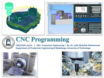
CNC Machine CentresProf. Janakarajan RamkumarProfessorDepartment of Mechanical and Design ProgramIIT Kanpur, India.
Index CNC machining centres CNC turning centres CNC milling centres Vertical machining centre 5-axis machining centre CNC travelling column Horizontal machining centre
CNC Machining centres The term “machining centres” describes almost any CNC milling anddrilling machine that includes an automatic tool changer and a tablethat clamps the workpiece in place. CNC machine centre is a advance manufacturing machine tool whichperforms wide range of machining operation with accuracy and goodquality surface finish. The orientation of the spindle is the most fundamental definingcharacteristic of a CNC machining centres.
CNC Machining centresVarious mechanisms used in CNC machining centers, there main aim is toreduce the production time and gives the best quality results.1. ATC (Automatic tool changer)2. APC (Automatic Pallet changer)3. Feedback systems4. Servo motors systems5. Re-circulating Ball screw and Nut
CNC Machining centresCNC machining centers can further be classified based on the rotation ofeither the work piece Or the rotation of the tool as:1. CNC turning machines2. CNC Milling machines
CNC Turning The primary function of a CNC Turning Center is that it rotates (or “turns”)your workpiece. CNC Turning Machines are one of the oldest and simplest forms ofmachining parts, called “lathes,” . Can be either horizontal or vertical depending on the weight andtolerance of the workpiece. Workpeices for this process are usually round, but can be other shapes —like squares or hexagons.
CNC Turning The workpiece is held in place by an instrument known as the “chuck.”The chuck then spins at various RPMs (depending on the capability ofyour machine). When this occurs, the machine’s tool moves into the rotating workpieceand begins to shave away material to create the desired shape.
CNC Turninghttps://giphy.com/explore/cnc
CNC Milling machines The primary function of a CNC Milling Machine is that your tool will bedoing the rotating and moving while your workpiece stays in one spot(generally). Milling is a more specific process that is similar to drilling and cutting. These machines can also be either horizontal or vertical, againdepending on the tolerance and weight of your workpiece. This process has many axes that allow for a variety of shapes, holes,and slots to be cut into the workpiece at many angles. These axes provide many different maneuvers, either by the spindle orthe bed, to cut the part desired to the exact specifications.
CNC Milling machineshttps://gfycat.com/gifs/search/milling machine
CNC Turning centreSchematic of a concrete bed of a CNC Turning centreRao, CAD/CAM Principles and Applications, 2010, TMH
CNC Turning centreRao, CAD/CAM Principles and Applications, 2010, TMH
CNC Turning centreSpindle design for a CNC turning centreRao, CAD/CAM Principles and Applications, 2010, TMH
CNC Turning centreSpindle design with an integral spindle motor and coolingsystem for CNC Machining 2918/
CNC Turning centreBifurcated column structure for CNC Machining centre to improve torsionalrigidityRao, CAD/CAM Principles and Applications, 2010, TMH
vCNC Machining centresAccording to the orientation of spindle, CNC machining centre can be classifiedas : Vertical machining centres (VMCs): generally favour precision while Horizontal machining centres (HMCs) generally favour production Universal Machining centres (UMC) 5 axis machining centre, which is able topivot the tool and/or the part in order to mill and drill at various orientations
CNC verticalmachining centre In CNC vertical machining center, the workpiece is held on the tablebase and the spindle which contains the cutting tool is fixed on verticalspindle Z axis. The table moves in X and Y axis and spindle with cuttingtool moves in Z axis.
CNC verticalmachining centre Travelling column Gantry structure Multiple spindle
CNC verticalmachining centre Present day production vertical axis CNC machining centre BridgeportVMC 500https://auctions.charterauctions.co.uk
5-Axis machinehttps://i.ytimg.com
CNC travelling columnRao, CAD/CAM Principles and Applications, 2010, TMH
CNC travelling column The possible rotary motions of the tool head of a CNC travelling columnRao, CAD/CAM Principles and Applications, 2010, TMH
5-Axis CNCtravelling columnhttp://www.asquithbutler.com
Gantry cnc machining centre A gantry type CNC machining centre DMC 65V for high speed machininghttps://5.imimg.com
4-axis CNC machine A 4-spindle CNC machining centre 4CUT for high speed machininghttps://5.imimg.com
Horizontal Machine centre Rotary table used in HMC for machining all four faces.Rao, CAD/CAM Principles and Applications, 2010, TMH
Horizontal Machine centre Spindle swivelling facility in HMC for machining in two different planes(XY as well as XZ)Rao, CAD/CAM Principles and Applications, 2010, TMH
Horizontal Machine centre Horizontal axis machining centre provided with a 2-axis rotary tablehttps://encrypted-tbn0.gstatic.com
Horizontal Machine centre Various planes possible by the 2-axis rotary table with a HMCRao, CAD/CAM Principles and Applications, 2010, TMH
Horizontal Machine centre A typical horizontal machining centre with an automatic pallet changer.Rao, CAD/CAM Principles and Applications, 2010, TMH
Pallet in HMC Typical pallet designs used with HMC, a) Pallet with holes; b) pallet withT-slotsRao, CAD/CAM Principles and Applications, 2010, TMH
.Pallet in HMC A typical pallet changer with a rotary style pallet changerRao, CAD/CAM Principles and Applications, 2010, TMH
Pallet in HMC A typical pallet changer with a shuttle pallet changer combined with a 6pallet carousal.Rao, CAD/CAM Principles and Applications, 2010, TMH
CNC Turning Centres Turn mill centres (X, Z, C) Multiple axis turning centres (X, Z, C, Y) Vertical turning centres Twin turret turning centres Multiple spindle turning centres Integrated material handling
CNC Turning Centres The slant bed of a CNC turning centrehttps://automatecnc.com
CNC Turning Centres Machining of a key way or drill a hole away from the centre of theworkpiece.Rao, CAD/CAM Principles and Applications, 2010, TMH
CNC Turning Centres The drive for tooling in the turret of a CNC turn mill centreRao, CAD/CAM Principles and Applications, 2010, TMH
CNC Turning CentresA tool turret with driven tooling to be used in CNC turn mill centre.https://www.ctemag.com
CNC Turning Centres Typical shapes of component that can be machined by the combinationof X, Z and C-axis movements.Rao, CAD/CAM Principles and Applications, 2010, TMH
.CNC Turning Centres CNC Turning centre with twin turretsRao, CAD/CAM Principles and Applications, 2010, TMH
CNC Turning Centres Twin spindle CNC Turning centrehttps://i.ytimg.com
CNC Turning Centres Twin spindle CNC Turning centre Mazak Dual Turn 20Rao, CAD/CAM Principles and Applications, 2010, TMH
CNC Turning Centres CNC turn Mill centre with Y-axis, Yamazaki Integrex 30https://5.imimg.com
CNC Turning Centres The types of machining that can be done using a CNC turn Mill centrewith Y-axisRao, CAD/CAM Principles and Applications, 2010, TMH
CNC Turning Centres CNC Vertical turning centre, Yamazakihttps://5.imimg.com
CNC Turning Centres CNC Vertical turning centre with inverted arrangement EMAG VSC250HDS,Rao, CAD/CAM Principles and Applications, 2010, TMH
Chip conveyors in CNCmachine toolsRao, CAD/CAM Principles and Applications, 2010, TMH
Summary What is CNC machining centres? What is CNC turning centres? What is CNC milling centres? Various Vertical machining centre 5-axis machining centre Various Horizontal machining centre Various pallet changer used in the CNC
Thank You
CNC ToolingProf. Janakarajan RamkumarProfessorDepartment of MechanicalIIT Kanpur, India.
Index CNC toolsCutting tools materialsHigh speed steel toolCement carbide toolsCeramics toolsISO coding system of toolsTools magazinesAutomatic tool changer (ATC)Modular accessories in CNC
CNC Tools The concept of computer numerical control (CNC) incorporates a widerange of machines that perform various functions. These CNC machinesare designed with precisely crafted tools to aid in the productionprocess If CNC machine is the brain, machine tools are the limbs- convertinginstructions into actual action. These tools perform precise cuts on metal, wood, steel, aluminum, anda variety of other materials. Multi-axis cutting tools can move in many directions, enabling the mostprecise cuts possible on the materials at-hand.
CNC ToolsAlthough all cutting tools serve one purpose, to cut through a material,there is a huge difference in their purpose.Normally, for a cutting tool to be effective, it has to: be 30% to 50% harder than the material it will work on.be easily fabricated.have high thermal conductivity.have low coefficient of friction.be very resistance to wear.be chemically inert and stable.
Cutting tool materials High Speed Steel Cemented Carbides Coated Carbides Ceramics
High Speed Steel It‘s composed of high carbon steel with a reasonable amount ofelement alloys like chromium, tungsten, and molybdenum. With this combination, it improves hardness, wear resistance, andtoughness. It also offers higher removal rate for metals and othermaterials. To improve its property, you’ve got to apply certain surface treatment. This property allows HSS to cut faster than high carbon steel, hence thename high-speed steel.
High Speed Steel The main use of high-speed steels continues to be in themanufacture of various cutting tools: drills, taps, milling cutters, toolbits, gear cutters Hobbing, saw blades, planer and jointer blades,router bits, Cutter-CNC-Tool-p-1376890.html
Cemented carbide Cemented carbide is a hard material used extensively as cutting toolmaterial, as well as other industrial applications. It consists of fine particles of carbide cemented into a composite by abinder metal. Cemented carbides commonly use tungsten carbide (WC),titanium carbide (TiC), or tantalum carbide (TaC) as the aggregate. Most of the time, carbide cutters will leave a better surface finish on thepart, and allow faster machining than high-speed steel or other toolsteels. Carbide tools can withstand higher temperatures at the cutterworkpiece interface than standard high-speed steel tools (which is aprincipal reason for the faster machining).
Cemented carbide Choose a grade with the lowest cobalt content and the finest grain sizeconsistent with adequate strength to eliminate chipping. Use straight WC grades if cratering, seizure or galling are notexperienced in case of work materials other than steels. To reduce cratering and abrasive wear when machining steel, use gradescontaining TiC. For heavy cuts in steel where high temperature and high pressuredeform the cutting edge plastically, use a multi carbide grade containingW-Ti-Ta and/or lower binder content.
Cemented oy-cemented-carbide-tools-8865787888.html
Ceramic cutting tools Ceramic cutting tools are constructed mainly from alumina (Al2O3) and siliconnitride (SiN). Recent advances have also introduced the use of silicon carbide (SiC) andceramic matrix composites (CMCs) in order to enhance the performance ofthe cutting tool. They all exhibit excellent hardness, toughness and thermal conductivity. The advantages of using ceramic materials in manufacturing revolve aroundceramic’s greater ability to withstand much higher temperatures than toolsmade from carbide or high-speed steel.
Usability of Ceramiccutting tools Use the highest cutting speed recommended and preferably selectsquare or round inserts with large nose radius. Use rigid machine with high spindle speeds and safe clamping angle. Machine rigid work pieces. Ensure adequate and uninterrupted power supply. Use negative rake angles so that less force is applied directly to theceramic tip. The overhang of the tool holder should be kept to a minimum; not morethan 1.5 times the shank thickness.
Usability of Ceramiccutting tools Large nose radius and side cutting edge angle on the ceramic insert toreduce the tendency of chipping. Always take a deeper cut with a light feed rather than a light cut withheavy feed; ceramic tips are capable of cuts as deep as one-half thewidth of the cutting surface on the insert. Avoid coolants with aluminium oxide based ceramics. Review machining sequence while converting to ceramics and if possibleintroduce chamfer or reduce feed rate at entry.
Ceramic cutting ://www.ceramtec.com/spk-cutting-materials/
ISO coding The ISO coding system for tungsten carbide inserts used in turning.TMH, New Delhi, CAD/CAM Principles and Applications by P N Rao, 3rd Ed
ISO coding The ISO coding system for tungsten carbide turning tool holders used inexternal turning (SCEA - side cutting edge angle, ECEA - end cutting edgeangle).TMH, New Delhi, CAD/CAM Principles and Applications by P N Rao, 3rd Ed
Contour capability The typical contour capability of external turning toolsTMH, New Delhi, CAD/CAM Principles and Applications by P N Rao, 3rd Ed
Contour capability The typical contour capability of internal turning toolsTMH, New Delhi, CAD/CAM Principles and Applications by P N Rao, 3rd Ed
Tooling used in turning centersTMH, New Delhi, CAD/CAM Principles and Applications by P N Rao, 3rd Ed page
Rao, CAD/CAM Principles and Applications, 2010, TMH CNC Turning Centres The drive for tooling in the turret of a CNC turn mill centre Rao, CAD/CAM Principles and Applications, 2010, TMH CNC Turning Centres A tool turret with driven tooling to be used in CNC turn mill centre. https://www.ctemag.com CNC Turning Centres Typical shapes of component that can be machined by the .
