Transcription
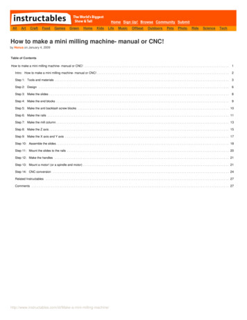
1Pro/MFG Volume Milling TutorialOBJECTIVES:The Manufacturing module in Pro/E is used to generate machine code to produceparts. This tutorial will focus on Pro/MFG Volume Milling. A volume milling NCsequence removes the material inside a Milling Volume slice by slice. All slices areparallel to the retract plane. Some typical applications for volume milling are: Facing down the workpiece General material removal on the side of the workpiece Rough milling of a vertical slot or cut, or a blind slit with islands Pocketing finishing by using the ROUGH OPTION parameter valuePROF ONLYPROCEDURES:Index:A. Product the part modelp. 1B. Create workpiecep. 6C. Perform the machining operation setupp. 8D. Define machine operations (create a mill volume) orp. 10E. Define machine operations (create a mill window -- the simplest way to definegeometry for a Volume milling NC sequence)F. Create cutter location file and NC codep. 14p. 17Start:A. Produce the part model. The part consists of two features, together forming ablock (4” x 8” x 1.5”) with raised letters “CAD” as shown in Figure 1.12.1. Start the Pro/E program. Windows menu items, Start All Programs PTC Pro ENGINEER Click on the iconPro ENGINEER.2. Set working directory. File Set Working Directory, select workingdirectory.3. Create the part name. Pro/E main menu, File New, select Part in the Newwindow, enter part name: CAD.4. Start of the part. The part contains some features already. The main graphicsarea shows 3 datum planes and a coordinate system as shown in Figure 1.1.
2Figure 1.1 Start of the Part5. Create a 4” x 8” x 1.5” rectangular block as shown in Figure 1.8. Choose INSERT EXTRUDE from the menu. You should see a newtoolbar called dashboard appear as shown in Figure 1.2.Figure 1.2 The Dashboard Click on the placement on the extrude dashboard (Figure 1.3) and selectdefine. The sketch dialog window appears as shown in Figure 1.4.Figure 1.3 The Extrude DashboardFigure 1.4 Sketch dialogChoose the datum place FRONT by clicking on it in the graphics window.Accept the default on the sketch dialog window and just click on theSketch button. References sub-window pop up as shown in Figure 1.5 andclick close to start sketch.
3Figure 1.5 References dialog Figure 1.6 The Sketcher toolbarChoose Create Rectangle icon on Sketcher Toolbar (Figure 1.6) to sketcha rectangle for extrusion in plane FRONT by clicking on the bottom-rightand top-left corners of the rectangle in the drawing windows. Clickmiddle mouse to finish drawing the rectangle.Modify the dimensions to 4 x 8 by double clicking on the dimensions onthe rectangle. To end sketching choose Accept icon on Sketcher Toolbar(Figure 1.6) and click OK in the Section dialog.Extrude the rectangle to form the solid block. Enter depth value as 1.5 intothe depth field of the extrude dashboard (Figure 1.3) and click the Accepttick to finish (Figure 1.7).View the rectangular block as shown in Figure 1.8. View Orientation Standard Orientation.Figure 1.7 Dashboard controls
4Figure 1.8 Block6. Create 2” x 6” x 0.5” letters “CAD” on top of the block as shown in Figure1.12. INSERT EXTRUDE from the menu. The dashboard appears as shownin Figure 1.2. Click on the placement on the extrude dashboard (Figure 1.2) and selectdefine. The sketch dialog window appears as shown in Figure 1.9. Choosetop surface of the block as sketch plane and accept the default on thesketch dialog window and click on the Sketch button. Produce letters. Sketch Text from the menu and pick two points on thesketch plan to determine the height of the text and enter letters CAM asshown in the figure 1.10. Modify the size of the text to 2 x 6 and locate thetext to the center of the block as shown in figure 1.11.Figure 1.9 Sketch dialogFigure 1.10 The Text dialog
5Figure 1.11 Letter CAD Extrude the text to 0.5” out of the block.View the created part (Figure 1.12). View Orientation StandardOrientation.Save the part. File Save and Exit or Close to continue.Figure 1.12 Part model
6B. Create the workpiece. The workpiece represents the raw stock of material fromwhich the part will be machined. Pro/E refers to this procedure as an assemblyoperation.1. Start the Pro/E program. Windows menu items, Start Programs PTC Pro ENGINEER Click on the iconPro ENGINEER.2. Set working directory. File Set Working Directory, select workingdirectory.3. Create the part name. Pro/E main menu, File New, select Manufacturing inType window and NC Assembly in Sub-type window, enter name: mfgCADas shown in Figure 1.13Figure 1.13 Creating a new fileFigure 1.14Figure 1.154. Load the part. From MANUFACTURE menu, select Mfg Model Assemble Ref. Model. Select cad.prt in the open window. The component Placementwindow pops up. Selectto place the part at default location as shown inFigure 1.16 and click OK. Click OK to close Create Reference Model asshown in Figure 1.17.Figure 1.16Figure 1.17
75. Create a workpiece 4”x 8”x2.25”. From MANUFACTURE menu, select MfgModel Create workpiece. Enter a name for the workpiece: wpcad.Select Solid Æ Protrusion Æ Extrude Æ Solid Æ Done. SelectNC ASM FRONT as sketch plane and NC ASM RIGHT as reference planein Figure 1.18. Create a rectangle 4”x8” surrounding the CAD part as shownin Figure 1.20 with references as shown in figure 1.19 and extrude it to 2.25”as shown in Figure 1.21.Figure 1.18Figure 1.9Figure 1.20
8Figure 1.21 Reference Model and WorkpieceC. Perform the machining operation setup. The setup consists of defining the typeof machine to use. It also requires defining a coordinate system if one does notalready exist and a retraction plane for the cutting tool. The coordinate systemmust match the mill orientation and the part zero.1. Insert Æ Model Datum Æ Coordinate system. Coordinate system window popup automatically as shown in Figure 1.22.2. Pick 3 references planes as shown in Figure 1.23 (Click two side and topplanes while holding down Ctrl key) to place the coordinate system.3. Orient X and Y axes (Figure 1.24) along the top edges as shown in Figure1.23 by clicking the Flip button as shown in Figure 1.24.Figure 1.22Figure 1.23Figure 1.24
94. MFG Setup Operation. Operation Setup window pops up automatically asshown in Figure 1.25.in Figure 1.25, Machine5. Define NC machine. Click NC machine iconTool Setup windows pop up as shown in Figure 1.26. Enter the parameters asshown belowMachine name: HAASMachine type: MillNumber of Axis: 3CNC control: VF-2Figure 1.25Figure 1.266. Define Machine Zero. Click Reference Machine Zero iconin Figure 1.25. Select the coordinate system ACS0 just created.7. Define retract plane. Click Retract Surface iconin Figure1.25. Retract Setup window pops up (Figure 1.28). Enter 0.5, click OK toclose the window. The retract plane is shown in Figure 1.29.8. Complete Operation setup. Click OK to close operation setup as Figure 1.30.MFG Setup Æ Done Æ Return.Figure 1.28Figure 1.29 Defining the Retract Surface
10Figure 1.30 Completed Operation SetupD. Define the machining operations (create mill volume). The setup consists ofdefining the type of tool to use and machining parameters (tools size, cuttingspeed, etc.), and specify the volume of material to be removed.1. Machining NC Sequence Volume 3 Axis Done.2. SEQ SETUP window pops up. Ensure that name, tool, parameters andvolume are checked and then choose DONE. (Figure 1.31).Figure 1.31
113. Enter NC sequence name: Volcut4. Tools setup table pops up. Enter the tool values cutter diameter 0.25” andlength 4” as shown in Figure 1.32 and APPLY OK.Figure 1.325. Edit Parameters window pops up. Input or change the values as shown inFigure 1.33. File Æ save as to file called “milprmVol” Æ click OK toexit.Figure 1.33
126. Select Mill Volume windows pop up as shown in figure 1.34. Since MillVolume has not been created, there is no volume to select. ClickTool to create the volume.Figure 1.34Figure 1.357. Create and Define a Volume. To specify the volume of material to beremoved. Click on Sketch Toolto sketch. Select NC ASM FRONT assketch plane and NC ASM RIGHT as Reference plane Right asshown in Figure 1.35. Sketch a rectangle window 4” x 8” exactly on the top of workpiece asshown in figure 1.36. Click onto exit sketch.Figure 1.36
13 Click on Extrude toolto the workpiece).to extrude a rectangle to 2.25” (similar We have sketched our entire workpiece. But we need to leave thematerial that represents our part. At this point Pro/E provides a Trimfunction that will “trim” the part from mill volume. Select Trim andselect the part we wish to be “trimmed” out of the mill volume asshown in Figure1.37. We have defined the volume to be removed (theworkpiece minus the part).Figure 1.378. View tool path. Machining Æ NC Sequence Æ Play path Æ NC Check.The cutting path is shown in Figure 1.38.Figure 1.389. After this completes choose DONE SEQ. If you don’t do this, you arelikely to lose the definition of this NC sequence.
14E. Define the machining operations (create mill windows). The setup consists ofdefining the type of tool to use and machining parameters (tools size, cuttingspeed, etc.), and specify the volume of material to be removed.1. Machining NC Sequence New Sequence Æ Volume 3 Axis Done.2. SEQ SETUP window pops up. Ensure that name, tool, parameters, andwindow are checked and then choose DONE. (Figure 1.39).Figure 1.393. Enter NC sequence name: Wincut4. Tool setup table pops up. Click ok to use tool 1 as previous tool (seeFigure 1.32).5. Edit parameters window pop up. File Æ open Æ select milprmVol Æopen Æ Ok (see figure 1.33).6. Select Wind window pop up as shown in figure 1.40. Since a windows hadnot been created, there is no windows to select. Click on Mill WindowsToolto create the window as shown in figure 1.41.Figure 1.40Figure 1.41
157. Create and define a Mill Window. To specify the volume of material to beremoved. We defined a “mill windows” on the top surfaceof ourworkpiece that include the entire workpiece. Think of the workpiece wasbeing transparent and the surface as being solid. If you look down throughthe mill windows, you will see all the volume of the material in theworkpiece located around the surface. to define the window plane andClick on the Sketch window typesketch the window. Select top surface as sketch plane and click on thedefine an Internal sketch to sketch as shown in Figure 1.42.Figure 1.42 Sketch Window pops up. Select NC ASM RIGHT as referenceRIGHT as shown in Figure 1.43. Click on Sketch.Figure 1.43 References Window pop up. Select two planes as shown in Figure1.44.Figure 1.44
16 Sketch a rectangle window 4” x 8” exactly on the top of the workpieceas shown in Figure 1.45. Click on. Click on Options and chooseON Window Contour as shown in Figure 1.46 and ClickFigure 1.45.Figure 1.468. View tool path. Machining Æ NC Sequence Æ Play path Æ NC Check.The cutting path is shown in Figure 1.47.Figure 1.479. After this completes Choose DONE SEQ. If you don’t do this, you arelikely to lose the definition of this NC sequence.
17F. Create cutter location file and NC code.1. Machining CL Data Output Select Feature NC Sequence volcut. PATH FILE Done. Enter name: volcut in the Save a Copywindow. Pro/E will save the file as volcut.ncl.1.2. The cutter location file can be converted to G-code file through Pro/E postprocessor for HAAS VF-2 CNC milling machine.3. Post Process on the CL DATA menu. Select the file volcut.ncl from theOpen Dialog box and select Open to close the window. In the PP Optionsmenu make sure the Verbose and Trace option are selected.4. Post processing is the act of converting the toolpaths from a standard languagefile, called a cutter location file (**.ncl), to the language of our specific CMCmachine controller, i.e.c G-codes.5. Select Done on the PP OPTIONS menu and a list of post processors appears.6. Choose the UNCX01.p15 Option.7. A file the the extension “.tap”, i.e., volcut.tap is created, which contain the Gcode.8. Close the information window and Select DONE/RETURN from CL DATAmenu.9. Open the volcut.tap file to view using program WORDPAD.The volcut.tap file is shown below:%N0005(FADAL VMC 6030 - 2N0045Y1.975 2%
Pro/MFG Volume Milling Tutorial . OBJECTIVES: The Manufacturing module in Pro/E is used to generate machine code to produce parts. This tutorial will focus on Pro/MFG Volume Milling. A volume milling NC sequence removes the material inside a Milling Volume slice by slice. All slices are parallel to the retract plane. Some typical applications for volume milling are: Facing down the .