Transcription
SolarEdgeSolarEdgeElectricity MeterInstallation GuideFor North AmericaVersion 1.0
DisclaimersDisclaimersImportant NoticeCopyright SolarEdge Inc. All rights reserved.No part of this document may be reproduced, stored in a retrieval system or transmitted, in any form orby any means, electronic, mechanical, photographic, magnetic or otherwise, without the prior writtenpermission of SolarEdge Inc.The material furnished in this document is believed to be accurate and reliable. However, SolarEdgeassumes no responsibility for the use of this material. SolarEdge reserves the right to make changes to thematerial at any time and without notice. You may refer to the SolarEdge web site(http://www.solaredge.us) for the most updated version.All company and brand products and service names are trademarks or registered trademarks of theirrespective holders.Patent marking notice: see http://www.solaredge.us/groups/patentThe general terms and conditions of delivery of SolarEdge shall apply.The content of these documents is continually reviewed and amended, where necessary. However,discrepancies cannot be excluded. No guarantee is made for the completeness of these documents.The images contained in this document are for illustrative purposes only and may vary depending onproduct models.FCC ComplianceThis equipment has been tested and found to comply with the limits for a Class B digital device, pursuantto part 15 of the FCC Rules. These limits are designed to provide reasonable protection against harmfulinterference in a residential installation. This equipment generates, uses and can radiate radio frequencyenergy and, if not installed and used in accordance with the instructions, may cause harmful interferenceto radio communications. However, there is no guarantee that interference will not occur in a particularinstallation. If this equipment does cause harmful interference to radio or television reception, which canbe determined by turning the equipment off and on, you are encouraged to try to correct theinterference by one or more of the following measures:lReorient or relocate the receiving antenna.lIncrease the separation between the equipment and the receiver.lConnect the equipment into an outlet on a circuit different from that to which the receiver isconnected.lConsult the dealer or an experienced radio/TV technician for help.Changes or modifications not expressly approved by the party responsible for compliance may void theuser’s authority to operate the equipment.SolarEdge-SolarEdge Electricity Meter Installation Guide MAN-01-00270-1.01
ContentsContentsDisclaimersImportant NoticeFCC ComplianceContentsHANDLING AND SAFETY INSTRUCTIONSSafety InformationChapter 1: IntroductionTerminologyThe SolarEdge Electricity MeterMeter Connection OptionsChapter 2: Meter InstallationInstallation GuidelinesInstalling and Connecting the MeterChapter 3: SolarEdge Device ConfigurationAppendix A: Troubleshooting Meter ConnectionCommunication Status Screen TroubleshootingDevice Type or Protocol are configured incorrectlyNumber of devices is not displayedMeter Status Screen Troubleshooting OK is not displayedAn error message is displayedTotal [Wh] value is not advancingMeter Status LEDsPower Status LEDsModbus Communication LEDsAppendix B: Installing Two MetersConnecting Two MetersConfiguring Dual-meter ConnectionVerifying Meter ConnectionTroubleshooting Dual-meter ConnectionCommunication Status Screen TroubleshootingDevice Type or Protocol are configured incorrectlyNumber of devices is lower than configured or not displayedMeter Status Screen TroubleshootingAppendix C: Meter Information Displayed in the Monitoring PortalAppendix D: Meter Technical SpecificationsAppendix E: External Lightning Protection 1919202121212121222324SolarEdge SolarEdge Electricity Meter Installation Guide MAN-01-00270-1.0
HANDLING AND SAFETY INSTRUCTIONSHANDLING AND SAFETY INSTRUCTIONSDuring installation, testing and inspection, adherence to all the handling and safety instructions ismandatory. Failure to do so may result in injury or loss of life and damage to the equipment.Safety InformationThe following safety symbols are used in this document. Familiarize yourself with the symbols and theirmeaning before installing or operating the system.WARNING!Denotes a hazard. It calls attention to a procedure that, if not correctly performed or adhered to, couldresult in injury or loss of life. Do not proceed beyond a warning note until the indicated conditionsare fully understood and met.Dénote un risque: il attire l'attention sur une opération qui, si elle n'est pas faite ou suivi correctement,pourrait causer des blessures ou un danger de mort. Ne pas dépasser une telle note avant que lesconditions requises soient totallement comprises et accomplies.CAUTION!Denotes a hazard. It calls attention to a procedure that, if not correctly performed or adhered to, couldresult in damage or destruction of the product. Do not proceed beyond a caution sign until theindicated conditions are fully understood and met.Dénote un risque: il attire l'attention sur une opération qui, si elle n'est pas faite ou suivi correctement,pourrait causer un dommage ou destruction de l'équipement. Ne pas dépasser une telle note avant queles conditions requises soient totallement comprises et accomplies.NOTEDenotes additional information about the current subject.IMPORTANT SAFETY FEATUREDenotes information about safety issues.SolarEdge-SolarEdge Electricity Meter Installation Guide MAN-01-00270-1.03
Chapter 1: IntroductionChapter 1: IntroductionTerminologyThe following terms are used in this document:lExport: The power injected to the grid.lImport: The power purchased from the grid.lExport/ Import meter: A meter that is installed at the grid connection point and reads theenergy/power exported/imported to/from the grid.lConsumption: The power consumed by the site.lConsumption meter: A meter that is installed at the load consumption point and reads theenergy/power consumed by the site.lSelf-consumption: The PV power consumed by the site and not fed into the grid.lProduction: The PV power produced by the PV system.lProduction meter: A meter that is installed at the inverter output or in the inverter (a built-in revenuegrade meter) and reads the energy/power produced by the PV system.Figure 1: Terminology4SolarEdge SolarEdge Electricity Meter Installation Guide MAN-01-00270-1.0
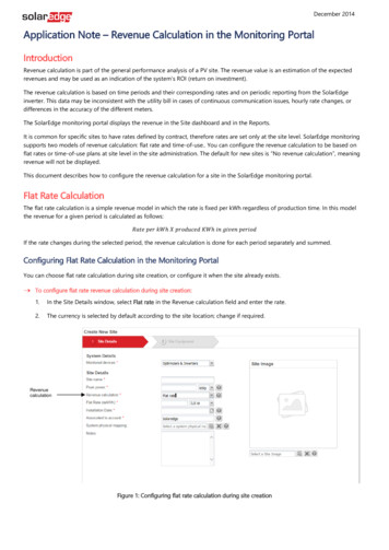
Chapter 1: IntroductionThe SolarEdge Electricity MeterThe SolarEdge meter enables measuring the power and energy of the photovoltaic (PV) system.The meter is used by the inverter for the following applications:lConsumption monitoringlExport limitationlStorEdge Smart Energy Management on-grid applicationsThe meter is built into an enclosure and requires two Current Transformers (CTs; available fromSolarEdge).The SolarEdge inverter or the Control and Communication Gateway (CCG) reads the exported powerfrom a meter installed at the grid connection point or reads the consumption from a meter installed atthe load consumption point.Figure 2: Typical installation with export meterFigure 3: Typical installation with consumption meterSolarEdge-SolarEdge Electricity Meter Installation Guide MAN-01-00270-1.05
Meter Connection OptionsMeter Connection OptionsIn a single inverter system, the meter is connected directly to the inverter. If your inverter has a built-inrevenue grade meter (RGM; the inverter is referred to a revenue grade inverter), you can connect anexternal meter on the same bus as the RGM (available form SolarEdge).Figure 4: Single-inverter connectionIn a multiple inverter system, two options are available:lThe meter is connected to the RS485 port of one of the inverters. In this case, as the inverter's RS485port is occupied by the meter, use an RS485 Expansion Kit (available from SolarEdge) or ZigBeecommunication between the inverters.lThe meter is connected to one of the RS485 ports of a CCG. The CCG’s second RS485 port can be usedto create an RS485 bus for communication between the inverters. This option is illustrated in Figure 5.Figure 5: Multi-inverter connection with CCG and meter6SolarEdge SolarEdge Electricity Meter Installation Guide MAN-01-00270-1.0
Chapter 2: Meter InstallationChapter 2: Meter InstallationThe meter is connected to the inverter using RS485.Installation GuidelinesAC wire specifications: 1.3 to 2.0 mm diameter / 16-12 AWG stranded wire, 600 V, type THHN, MTW, orTHWN.RS485 wiring specifications:lCable type: Min. 3-wire shielded twisted pair (a 4-wire cable may be used)lWire cross-section area: 0.2- 1 mm²/ 24-18 AWG (a CAT5 cable may be used)NOTEIf using a cable longer than 10 m/33 ft in areas where there is a risk of induced voltage surges bylightning, it is recommend to use external surge protection devices. For details refer to ExternalLightning Protection Connection on page 24. If grounded metal conduit are used for routing thecommunication wires, there is no need for a lightning protection device.lllllllThe meter is considered “permanently connected equipment” and requires a disconnect means(circuit breaker, switch, or disconnect) and overcurrent protection (fuse or circuit breaker).The meter draws 10-30mA, therefore the rating of any switches, disconnects, fuses, and/ or circuitbreakers is determined by the wire gauge, the mains voltage, and the current interrupting ratingrequired.The switch, disconnect, or circuit breaker must be located near the meter and be easily operated .Use circuit breakers or fuses rated for 20A or less.Use grouped circuit breakers when monitoring more than one line.The circuit breakers or fuses must protect the mains terminals labeled L1, L2, and L3. In the rare caseswhere neutral has overcurrent protection, the overcurrent protection device must interrupt bothneutral and the ungrounded conductors simultaneously.The circuit protection / disconnect system must meet all national and local electrical codes.Installing and Connecting the MeterMount the meter on a wall or pole using the supplied bracket.To mount the meter:1. Install the bracket with the semi-circles facing down, as shown below. Verify that the bracket is firmlyattached to the mounting surface.Figure 6: Mounting bracketSolarEdge-SolarEdge Electricity Meter Installation Guide MAN-01-00270-1.07
Installing and Connecting the Meter2. Loosen the 4 Allen screws of the meter enclosure and remove the cover.Figure 7: Meter front view without cover3. Carefully move the terminal block end-stops to the sides of the meter and remove the terminalblocks.4. Open one or more conduit knockouts according to the conduits used in the installation: Open therequired knockout(s), each with two sizes: ¾'' and 1'', taking care not to interfere with any of theinternal components. A Unibit drill may be used.CAUTION!Use only knockouts located at the bottom, back and sides of the enclosure. Opening the topknockouts may damage the protection rating of the enclosure.Figure 8: Meter - rear view5. Mount the meter: Attach the meter enclosure back brackets to the mounted bracket using the foursupplied screws. Tighten the screws with a torque of 9 N*m / 6.6 lb*ft.To install the CTs:1. Turn off AC power before clamping on current transformers.2. Install the CTs around the conductor to be measured. Split-core CTs can be opened for installationaround a conductor. A nylon cable tie may be secured around the CT to prevent accidental opening.3. Install the CT with the arrow pointing to the grid for consumption or export measurement.8SolarEdge SolarEdge Electricity Meter Installation Guide MAN-01-00270-1.0
Chapter 2: Meter InstallationTo wire the meter:If you are connecting the meter to a revenue grade inverter, refer to Installing Two Meters on page 19.Refer to the connection diagram below:Figure 9: Meter connectionsNOTElClamp the CT connected to L1 CT around the wire connected to ØL1.lClamp the CT connected to L2 CT around the wire connected to ØL2.1. Verify that power is OFF before making connections.2. Insert a grounding cable through the appropriate conduit and the knockout that was opened andconnect it from Pin 10 of the 10-pin terminal block to the grounding terminal (bus-bar) at the bottomof the meter enclosure.3. Connect the AC side wires (meter input) using the 10-pin terminal block:a. Insert the wires through the appropriate conduit and the knockout that was opened.b. Loosen the appropriate screws on the 10-pin terminal block.c. Connect each AC wire to the appropriate screw terminal (pins 6, 4). Verify that the lines matchthe symbols printed on the meter front label.d. Connect ground to pin 10 and neutral to pin 8.e. Tighten the screws making sure the wires are fully inserted and cannot be pulled out easily.f. Insert the 10-pin terminal block into the socket on the meter making sure it is fully seated in themeter.4. Connect the CT wires to the 6-pin terminal block:a. Insert the wires through the appropriate conduit and the knockout that was opened.b. Connect the black and white wires according to the dots printed on the label: White to L1/L2white (pins 1/3), and black to L1/L2 black (pins 2/4).c. Insert the 6-pin terminal block into the socket on the meter making sure it is fully seated in themeter5. Connect the RS485 twisted pair cable to the 4-pin terminal block of the meter:a. Insert the wires through the appropriate conduit and the knockout that was opened.b. Connect the wires to the A and B- terminals, and connect the shield to the G terminal.c. Insert the 4-pin terminal block into the socket on the meter making sure it is fully seated in themeter6. Return the terminal block end-stops to the sides of the meter.SolarEdge-SolarEdge Electricity Meter Installation Guide MAN-01-00270-1.09
Installing and Connecting the MeterTo connect the meter to the inverter or CCG:1. If connecting to an inverter, remove the seal from one of the openings in communication gland #2 atthe bottom of the inverter and insert the RS485 wires from the meter through the opening.Figure 10: Communication glands2. Prepare to connect to one of the available RS485 ports of the device, as shown below:lInverter RS485-1 - pull out the 9-pin RS485 connector located on the communication board.Figure 11: Inverter RS485 connectorlInverter RS485 Expansion module - pull out the 3-pin connectorFigure 12: Inverter RS485 Expansion modulelCCG - use one of the 3-pin connectors supplied with the CCG. Connect it to the RS485-2connection on the CCG.Figure 13: CCG RS485 connector10SolarEdge SolarEdge Electricity Meter Installation Guide MAN-01-00270-1.0
Chapter 2: Meter Installation3. Connect the wires as shown below:Figure 14: Meter RS485 connections4. If the SolarEdge device is at the end of the RS485 bus, terminate as follows:llInverter - Terminate by switching a termination DIP-switch inside the inverter to ON (topposition). The switch is located on the communication board and is marked SW7.CCG - Terminate by switching the SW2 termination DIP-switch to ON.Figure 15: RS485 termination switchSolarEdge-SolarEdge Electricity Meter Installation Guide MAN-01-00270-1.011
Chapter 3: SolarEdge Device ConfigurationChapter 3: SolarEdge Device ConfigurationThis section describes basic configuration of SolarEdge devices (inverter/CCG) for using a meter. Inaddition, configuration specific to the application being used is required in some cases. Refer to thefollowing documents:lExport Limitation - http://www.solaredge.us/files/pdfs/products/export limitation applicationnote NA.pdflConsumption and Production Monitoring ption production monitoring applicationnote.pdflStorEdge Smart Energy Management off-grid applications http://www.solaredge.us/files/pdfs/storedge backup installation guide NA.pdf.For configuring two connected meters refer to Installing Two Meters on page 19.To configure the SolarEdge device:Use the four user buttons to control the LCD panel menus:lEsc: Goes to the beginning of the currently entered parameter or to the previous menu.lUp (1) and Down (2): Moves the cursor ( ) to the relevant menu option.lEnter (3): Used to select an option1. Verify that the device ON/OFF switch is OFF.2. Turn ON the AC switch of the main circuit board.WARNING!ELECTRICAL SHOCK HAZARD. Do not touch uninsulated wires when the inverter cover isremoved.RISQUE D’ÉLECTROCUTION, ne touchez pas les fils non isolés lorsque le couvercle de l'onduleurest retiré.3. Press the Enter (3) button for at least five seconds. The following message is displayed:PleaseenterPassword********4. Use the three right most buttons (Up-1, Down-2 and Enter-3) to type in the following defaultpassword: 12312312.5. Scroll to the Communication menu and select RS485-X Conf (X represents the actual RS485 port towhich the electricity meter is connected: 1 or E for the inverter; 1 or 2 or E for the CCG). The followingscreen is displayed:DeviceTypeProtocolDevice12 SE M ID 1 SlaveDetectSlaveList # # SolarEdge SolarEdge Electricity Meter Installation Guide MAN-01-00270-1.0
Chapter 3: SolarEdge Device Configuration6. Select Device Type. the following screen is displayed:SolarEdgeNon-SE M Logger S Meter M Multi-devices M RevenueNone7. Select Revenue Meter, the following screen is displayed:DeviceTypeProtocolDeviceCT MTR WN ID 1 Rating 0 MeterFunc. None 8. Configure the meter parameters as follows:lSelect Protocol è WattNode.lSelect Device ID: 2lSet the CT rating to the value that appears on the CT: CT Rating è xxxxA . The default is 5Amperes. If the displayed rating is 0 or you cannot change the value, there is no communicationwith the meter. Check that the AC power to the meter is on.lSelect Meter Func. and select one of the functionality options, according to the installed meterspecifications and location.Export ImportExportConsumptionProductionImportNoneExport Import: The meter is installed at the grid connection point and reads pulses from bothdirections - export and import energy.o Export: The meter is installed at the grid connection point and reads the export energy.o Consumption: The meter is installed at the load consumption point and reads the energyconsumed by the site.o Production: The meter is installed at the inverter output and reads the energy produced bythe inverter.o Import: The meter is installed at the grid connection point and reads the import energy.o None: No readingThe selected option is displayed in the RS485 Conf screen as E I , E , Cons , Prod , I , None .9. Exit Setup mode.oNOTECalculated meter readings, such as self-consumption, are calculated using the data measured bythe meter and the inverters. Calculated meters are only sent when Energy Manager is enabled(for details refer to http://www.solaredge.us/files/pdfs/products/export limitation applicationnote NA.pdf).SolarEdge-SolarEdge Electricity Meter Installation Guide MAN-01-00270-1.013
Chapter 3: SolarEdge Device ConfigurationTo verify meter connection:1. Press the Enter button or the LCD external button until the Communication status screen isdisplayed as shown below. This screen shows the number of external devices that communicate oneach port, the device type, and the protocol to which each port was configured.2. Verify that the setting of the relevant RS485 port is correct and that the port is communicating withthe meter.For example, if the meter is connected to the RS485-1 port, the Communication status screen shoulddisplay the following:wwwwwwwDevProtRS485-1 MTR WN ##1 RS485-2 -- - -- -- ZigBee -- - -- -- Dev: the type of device configured to this port. MTR indicates a meter.Prot: the communication protocol## 1: Indicates that the connection to the meter is successful.3. Press the Enter button or the LCD external button until reaching the meter status screen showingthe total energy [Wh]. If there is more than one meter/function, there is a status screen for each one.The following is
SolarEdge). The SolarEdge inverter or the Control and Communication Gateway (CCG) reads the exported power from a meter installed at the grid connection point or reads the consumption from a meter installed at the load consumptio