Transcription
Disclaimers2SolarEdge Installation Guide – MAN-01-00002-1.6DisclaimersImportant NoticeCopyright SolarEdge Inc. All rights reserved.No part of this document may be reproduced, stored in a retrieval system or transmitted, inany form or by any means, electronic, mechanical, photographic, magnetic or otherwise,without the prior written permission of SolarEdge Inc.This document is solely for the use of SolarEdge customers and employees.The material furnished in this document is believed to be accurate and reliable. However,SolarEdge assumes no responsibility for the use of this material. SolarEdge reserves theright to make changes to the material at any time and without notice. You may refer to theSolarEdge web site (www.solaredge.com) for the most updated version.All company and brand products and service names are trademarks or registeredtrademarks of their respective holders.Exclusion of LiabilityThe general terms and conditions of delivery of SolarEdge shall apply.The content of these documents is continually reviewed and amended, where necessary.However, discrepancies cannot be excluded. No guarantee is made for the completeness ofthese documents.
Table of Contents3SolarEdge Installation Guide – MAN-01-00002-1.6Table of ContentsDisclaimers . 2Handling and Safety Instructions . 6Support and Contact Information . 8Chapter 1: Introducing the SolarEdge PowerHarvesting System . 9What is the SolarEdge Power Harvesting Solution? . 9SolarEdge Power Optimizer . 9Single Phase Inverter . 10SolarEdge Monitoring Portal . 11Installation Workflow. 12Transport and Storage . 13Single Phase Inverter Transport. 13Single Phase Inverter Storage . 13Equipment List. 13Chapter 2: Installing the Power Optimizers . 15Applicable Notes and Warnings . 15Step 1, Mounting the Power Optimizers . 18Step 2, Connecting Each PV Module to a Power Optimizer . 20OP250-LV, OP300-MV and OP400-MV . 20PB250-AOB and PB350-AOB . 21Connecting Power Optimizers . 22Step 3, Connecting Power Optimizers in Strings . 23Verifying Proper Power Optimizer Connection . 24Step 4, Recording Installation Information . 26Chapter 3: Installing the Inverter . 27Identifying the Inverter . 27Selecting the Mounting Location . 27Chassis Clearance . 27Mounting the Inverter . 28Connecting the Inverter . 31Inverter Connection Overview . 31AC Grids Supported . 34Connecting the Single Phase Inverter . 35
Table of Contents4SolarEdge Installation Guide – MAN-01-00002-1.6Completing the Single Phase Inverter Installation. 41Installing the AC/DC Safety Switch . 42Ground Fault Circuit Interrupter . 55Chapter 4: Commissioning the Installation . 56Commissioning – Workflow . 56Step 1, Activating the System . 57Step 2, Pairing Power Optimizers to the Inverter . 58Step 3, Verifying Proper Operation . 60Step 4, Reporting and Monitoring Installation Data . 61Chapter 5: Replacing and Adding System Components . 64Modifying an Existing Installation . 64Chapter 6: Setting Up Communication . 66Communication Dataflow . 66Connector Panel . 66Communication Types . 67Creating an RS232 (UART) Connection . 69Creating an Ethernet (LAN) Connection. 70Creating an RS485 Bus Connection . 75Verifying the Connection . 81Troubleshooting Communication . 82Chapter 7: Inverter User Interface . 83Inverter LCD Panel and LEDs . 83Inverter LCD Panel and User Buttons . 84Configuring the Inverter Using the LCD Panel and User Buttons. 88Inverter Configuration Menu Options . 95LCD Button Menu Options . 98Configuring the Inverter Using the SolarEdge Configuration Tool. 99Appendix A: Errors and Troubleshooting . 100Appendix B: Technical Specifications . 108Single Phase Inverter . 108OP250-LV, OP300-MV and OP400-MV . 111PB250-AOB and PB350-AOB . 113
Table of Contents5SolarEdge Installation Guide – MAN-01-00002-1.6Appendix C: Power Optimizer MechanicalSpecifications . 115OP250-LV, OP300-MV, OP400-MV Power Optimizers . 116PB250-AOB and PB350-AOB Power Optimizers . 117Appendix D: Inverters Power De-rating . 118Appendix E: Limited Product Warranty . 119
Handling and Safety Instructions6SolarEdge Installation Guide – MAN-01-00002-1.6Handling and Safety InstructionsDuring installation, testing and inspection adherence to the following handlingand safety instructions is mandatory.Safety SymbolsThe following safety symbols are used throughout this document. Familiarizeyourself with the symbols and their meaning before installing or operating thisinstrument.WARNING!Denotes a hazard. It calls attention to a procedure that, if not correctly performedor adhered to, could result in injury or loss of life. Do not proceed beyond awarning note until the indicated conditions are fully understood and met.Dénote un risque: il attire l'attention sur une opération qui, si elle n'est pas faite ousuivi correctement, pourrait causer des blessures ou un danger de mort. Ne pasdépasser une telle note avant que les conditions requises soient totallementcomprises et accomplies.CAUTION:Denotes a hazard. It calls attention to a procedure that, if not correctly performedor adhered to, could result in damage or destruction of the instrument. Do notproceed beyond a caution sign until the indicated conditions are fully understoodand met.Dénote un risque: il attire l'attention sur une opération qui, si elle n'est pas faite ousuivi correctement, pourrait causer un dommage ou destruction de l'équipement.Ne pas dépasser une telle note avant que les conditions requises soienttotallement comprises et accomplies.NOTE:Denotes additional information about the current subject.IMPORTANT SAFETY FEATURE:Denotes information about safety issues.
Handling and Safety Instructions7SolarEdge Installation Guide – MAN-01-00002-1.6InstructionsWARNING!The cover must only be opened after shutting off the AC/DC switch located belowthe inverter and waiting five minutes. This removes both DC and AC voltage fromthe inverter.Do not remove the inverter cover before five minutes have elapsed afterdisconnecting all sources of power. Only use lockable connectors for DC input.Otherwise, there is a risk of electric shock form energy stored in the capacitor.Ne pas ouvrir le couvercle de l'onduleur avant d'avoir coupé l'interrupteur CA/CCsitué en dessous de l'onduleur et que cinq minutes ne se soient ecoulées. Celasupprime les tensions CC et CA de l'onduleur.Ne pas ouvrir le couvercle de l'onduleur avant que cinq minutes ne se soientecoulées après coupure de toutes les sources de puissance. Sinon, il y a unrisque de choc électrique provenant de l'énergie stockée dans le capaciteur.WARNING!Before operating the Single Phase Inverter, ensure that the system has beengrounded properly.Avant d'utiliser l'onduleur monophasé, assurez-vous que le système estcorrectement mis à la terre.WARNING!No user-serviceable parts inside. This unit must be opened only by qualifiedservice personnel. Repairs or testing under power must only be performed byqualified service personnel who are familiar with and qualified to work with thisSingle Phase Inverter.Ne contient aucune pièce réparable par l'utilisateur. L’unité ne doit être ouverteque par un technicien qualifié dans le cadre de l'installation et de la maintenance.Les réparations ou les tests électriques sous tension ne doivent être effectuésque par des techniciens qualifiés de SolarEdge, possèdant les connaissances etles qualifications nécessaires pour travailler avec cet onduleur monophasé.WARNING!The supplied AC/DC Safety Switch meets all requirements for a code-compliantinstallation of this ungrounded system. The DC section opens both the positiveand negative conductors.Le sectionneur CA/CC externe (inclus) repond aux exigences de conformité pourl’installation de ce système non-relié à la terre. Le coupeur CC ouvre lesconducteurs positif et négatif.
Support and Contact Information8SolarEdge Installation Guide – MAN-01-00002-1.6WARNING!This unit must be connected only to a dedicated AC branch circuit with amaximum Overcurrent Protection Device (OCPD) of 40 A.Cet appareil doit être connecté uniquement à un circuit de dérivation dédié avecun coéfficient TPOC (dispositif de protection contre les surintensités) maximal de40 A.Support and Contact InformationIf you have technical problems concerning our products, please contact us:USA and Canada: 1877 360 5292Germany:France:Italy:United Kingdom:Israel:Australia:Rest of World:Fax:Email to: 089-45459730 and 089-4161703-390800917410800 784 82408002061058073 24031181800149229 1 (650) 319-8843 972 73 240-3117support@solaredge.com (US and Canada)support@solaredge.com (all other countries)Before contact, please gather the following information: Inverter and power optimizer type.Serial number of the inverter and the power optimizer in question.The error indicated on the inverter screen or on the SolarEdge MonitoringPortal.System configuration information, including the type and number of modulesconnected and the number and length of strings.The communication method to the SolarEdge server.The Supportoption on the top right of the SolarEdge Configuration Tool’smain window can be used to automatically collect all relevant information to besent to SolarEdge Professional Services for support. This option is described indetail in the SolarEdge Configuration Tool Software Guide.
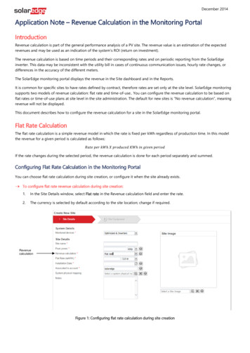
Introducing the SolarEdge Power Harvesting System9SolarEdge Installation Guide – MAN-01-00002-1.6Chapter 1Introducing the SolarEdge PowerHarvesting SystemWhat is the SolarEdge PowerHarvesting Solution?The SolarEdge power harvesting solution maximizes the power output from anytype of solar PV installation while reducing the average cost per watt. Thesections below describe each of the system’s components.SolarEdge Power OptimizerSolarEdge power optimizers can be connected to existing PV modules in order tomaximize power harvesting by locally performing Maximum Power PointTracking (MPPT) at the PV module level.The power optimizers keep the string voltage fixed, regardless of the length of thestring and of the environmental conditions. Each SolarEdge power optimizerdirectly transmits performance data from every PV module over the power line.Three types of power optimizers are provided by SolarEdge, as follows: Module add-on solutions, connected during installation to one or more PVmodule. P/N: OP250-LV, OP300-MV, OP400-MV, OP480-IV, PB250-AOBand PB350-AOB.Module Embedded Solution (CSI), is supplied embedded into a PVmodule.
Introducing the SolarEdge Power Harvesting System10SolarEdge Installation Guide – MAN-01-00002-1.6You may refer to the SolarEdge power optimizer datasheets in order to determinewhich power optimizer is most suitable for you requirements.Mounting HoleMounting HoleFigure 1: Add-On Box SolutionSingle Phase InverterThe Single Phase Inverter efficiently converts DC power received from the PVmodules into AC power that can be fed into the main circuit board of the site andfrom there to the grid. The inverter also receives the monitoring data from eachpower optimizer and transmits it to a central server (called the Monitoring Server)through an Ethernet network to an external modem connection.Heat Sink FinsTopFrontLCDBottomFigure 2: Single Phase Inverter
Introducing the SolarEdge Power Harvesting System11SolarEdge Installation Guide – MAN-01-00002-1.6Single Phase Inverter Package ContentsThe following lists the contents of the Single Phase Inverter installation package: One SolarEdge Single Phase Inverter.One wall-mounting bracket.Two flat head screws for fastening the inverter to the wall-mounting bracket.Installation Guide.Quick Installation Guide.SolarEdge Monitoring PortalThe SolarEdge Monitoring Portal enables you to monitor the technical andfinancial performance of one or more SolarEdge Photovoltaic sites. It providesinformation about present and past performance of each PV module individuallyand about the system as a whole.NOTE:You may refer to the SolarEdge Monitoring Portal User Guide available on theSolarEdge website at www.solaredge.com for more information about this option.
Introducing the SolarEdge Power Harvesting System12SolarEdge Installation Guide – MAN-01-00002-1.6Installation WorkflowThe following provides an overview of the workflow for installing and setting upa new SolarEdge site. Most of these procedures can also be used for addingcomponents to an existing SolarEdge site.Connecting Power Optimizersto Panels and to a StringRecording Power Optimizer SerialNumbersPage 15Pages 26 and 61Installing the Inverter andConnecting the String to theInverterPage 27Commissioning and Activating theInstallationPage 56Connecting the Inverter to theSolarEdge Monitoring ServerPage 66Configuring the InverterPage 88
Introducing the SolarEdge Power Harvesting System13SolarEdge Installation Guide – MAN-01-00002-1.6Transport and StorageSingle Phase Inverter TransportThe Single Phase Inverter should be transported in its original packaging, facingup and without exposing the Single Phase Inverter to unnecessary shocks. If theoriginal package is no longer available, a similar box can be used which canwithstand the weight of the Single Phase Inverter ( 52 lb/25 kg), has a handlesystem and can be closed fully.Single Phase Inverter StorageStore the Single Phase Inverter in a dry place where ambient temperatures arealways between -25 C and 60 C.Equipment ListStandard tools can be used during the installation of the SolarEdge system. Thefollowing is a recommendation of the equipment to be used when installing aSolarEdge system: Allen screwdriver for M6 and M5 screw types.Flat Head screwdriver.Electrical screwdriver (tester).Drilling machine and bits suitable for a wall or pole, where the invertermounting bracket is installed.Suitable screws for attaching the inverter mounting bracket to a wall.5/16” screws for attaching the power optimizer to the racking.Wire cutters.Wire strippers.Voltmeter.
Introducing the SolarEdge Power Harvesting System14SolarEdge Installation Guide – MAN-01-00002-1.6For installing the communication option, you may also need the following: For Ethernet: RJ45 connectorsFor RS485: Four- or six-wire twisted pair telephone cableAn inverter has either RJ45/RJ11 connectors or block terminal connectors forcommunication. To install an inverter with RJ45/RJ11 connectors, you alsorequire the following: For Ethernet: CAT5 twisted pair Ethernet cable RJ45 crimping toolFor RS485: RJ11 six-pin connector (also known as RJ25) RJ11 crimping tool
Installing the Power Optimizers15SolarEdge Installation Guide – MAN-01-00002-1.6Chapter 2Installing the Power OptimizersApplicable Notes and WarningsThe following notes and warnings apply when installing the SolarEdge poweroptimizers:WARNING:Before performing these steps, turn OFF the Single Phase Inverter by turning off theON/OFF switch at the bottom of the inverter. All inverters in an installation site mustbe switched OFF in this manner.Avant de faire ces étapes, éteignez l'onduleur monophasé en mettant sur OFFl'interrupteur ON/OFF situé au bas de l'onduleur. Tous les onduleurs sur un sited'installation doivent être etteints de la même manière.CAUTION:If installing directly on the module or module frame, first consult the modulemanufacturer for guidance regarding location and the impact on the modulewarranty.Pour installation à même le module ou la monture du module, consultez d'abord lefabricant du module sur la position et son impact sur la garantie du module.CAUTION:Unused connectors must be sealed with appropriate plugs (not provided). Leavingconnectors exposed may be unsafe or create funcional problems in the installationand will void the warranty.Les connecteurs non-utilisés doivent être scellés avec des bouchons (non-fournis).Laisser des connecteurs exposés peut être dangereux ou peut créer des problèmesfonctionels lors de l’installation et par conséquent ne seront pas couvert par laguarantie.
Installing the Power Optimizers16SolarEdge Installation Guide – MAN-01-00002-1.6CAUTION:SolarEdge power optimizers and inverters use connectors from the followingmanufacturers: Multi Contact MC4Amphenol H4Tyco keyed connectorHuber Suhner RaddoxInstalling a SolarEdge system without ensuring compatibility of the moduleconnectors with the optimizer connectors may be unsafe and could causefunctionality problems s
SolarEdge Installation Guide – MAN-01-00002-1.6 12 Installation Workflow The following provides an overview of the workflow for installing and setting up a new SolarEdge site. Most of these procedures can also be used for adding components to an existing SolarEdge site. Page 15 Pages 26 a