Transcription
Technologies in the HP BladeSystem c7000Enclosuretechnology brief, 4th editionAbstract . 3Overview of HP BladeSystem c7000 Enclosure . 3Enclosure management . 5BladeSystem Onboard Administrator . 5Detecting component insertion and removal . 6Identifying components . 6Managing power and cooling . 6Controlling components. 7Redundant enclosure management . 8User interfaces for the BladeSystem Onboard Administrator . 8Security . 8Role-based user accounts. 9Enclosure linking . 9ProLiant Onboard Administrator (Integrated Lights-Out 2) for ProLiant server blades . 10Insight Display . 10HP Insight Control suite . 11Interconnect options and infrastructure. 12Interconnect modules . 13Server blades . 14Storage options inside the BladeSystem enclosure . 14Direct attach storage blades . 14Shared storage . 15External SAS connectivity with direct connect SAS storage for HP BladeSystem . 15NAS/SAN Gateway . 15Storage server. 15Mezzanine cards . 16Virtual Connect . 16Fabric connectivity and port mapping . 17c7000 bay-to-bay crosslinks . 19Device bay crosslinks . 19Interconnect bay crosslinks . 19HP Thermal Logic technologies . 20Active Cool 200 fans . 20HP PARSEC architecture . 21Parallel. 21Redundant . 23Scalable . 24Thermal Logic for the server blade . 24Power supplies and enclosure power subsystem . 25Pooled power . 27
Dynamic Power Saver mode . 29Power Regulator . 30Basic Power Capping for each server blade . 30HP Dynamic Power Capping . 30HP BladeSystem Power Sizer . 31Conclusion . 31Appendix: Fan and server population guidelines . 32Fan bay numbering . 32Server blade bay numbering . 32Enclosure blade zones . 33For more information . 35Call to action . 352
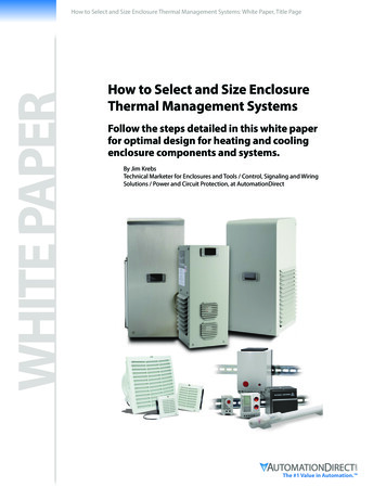
AbstractThe HP BladeSystem c7000 Enclosure is an evolution of the entire rack-mounted infrastructure. Itconsolidates and repackages all the supporting infrastructure elements―compute, storage, network,and power―into a single ―infrastructure-in-a-box‖ that accelerates the integration and optimization ofthe data center. This technology brief provides an overview of the HP BladeSystem c7000 Enclosure,including Thermal Logic power and cooling technologies and interconnect options.It is assumed that the reader is familiar with HP ProLiant server technology and has some generalknowledge of BladeSystem architecture. More information about the infrastructure components andBladeSystem technologies is available on the HP website: www.hp.com/go/bladesystem.Overview of HP BladeSystem c7000 EnclosureThe HP BladeSystem c7000 Enclosure was the first enclosure implemented using the BladeSystemc-Class architecture.1 It is optimized for enterprise data center applications. It fits into standard sizeHP and third-party racks; accommodates BladeSystem c-Class server blades, storage blades, andinterconnect modules; and provides all the power, cooling, and I/O infrastructure needed to supportthem throughout the next several years.The c7000 enclosure can be populated with the following components:Up to 8 full-height (FH) or 16 half-height (HH) server, storage, or other option blades per enclosureUp to eight interconnect modules simultaneously supporting a variety of network interconnect fabricssuch as Ethernet, Fibre Channel (FC), InfiniBand (IB), Internet Small Computer System Interface(iSCSI), or Serial-attached SCSI (SAS)Up to 10 Active Cool 200 fan kitsUp to six power suppliesRedundant BladeSystem Onboard Administrator (OA) management modules (optional activestandby design)Figures 1 and 2 show front and rear views of the c7000 enclosure. The c7000 enclosure and thec3000 enclosure support many of the same critical components such as servers, interconnects,mezzanine cards, storage blades, power supplies, and fans.HP also offers the HP BladeSystem c3000 Enclosure, which is optimized for remote sites or small businesses.More information about the c3000 enclosure is in the technology brief titled ―HP BladeSystem c3000 .pdf .13
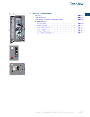
Figure 1. HP BladeSystem c7000 Enclosure – front viewFigure 2. HP BladeSystem c7000 Enclosure – rear viewThe c7000 enclosure is10U high and includes a shared, 5-terabit-per-second, high-speed NonStopmidplane for wire-once connection of server blades to network and shared storage. A pooled-powerbackplane delivers power and ensures that the full capacity of the power supplies is available to allserver blades and interconnects. The enclosure is available with either a single-phase AC, three-phaseAC, or -48V DC power subsystem to meet the needs of the data center power infrastructure.The c7000 Enclosure has redundant signal paths between servers and interconnect modules(Figure 3). The NonStop signal midplane and separate power backplane in the c7000 enclosurehave no active components. Separating the power delivery in the backplane from the high-speedinterconnect signals in the midplane results in minimal thermal stress to the signal midplane.4
Figure 3. HP BladeSystem c7000 Enclosure – side viewEnclosure managementThe HP BladeSystem c7000 Enclosure has extensive embedded management capabilities based onthree management elements:BladeSystem Onboard Administrator or BladeSystem Onboard Administrator with KVMProLiant Onboard Administrator powered by Integrated Lights-Out 2 (iLO 2) managementprocessors that are integrated on the server bladesInterconnect module management processors such as the HP Virtual Connect ManagerThese integrated management elements provide powerful hardware management for remoteadministration and local diagnostics, as well as component and enclosure troubleshooting.For detailed information about c-Class management technologies and capabilities, refer to the HPwhite paper titled ―Managing HP BladeSystem c-Class rt/SupportManual/c00814176/c00814176.pdf .BladeSystem Onboard AdministratorThe heart of c-Class enclosure management is the BladeSystem Onboard Administrator modulelocated in the enclosure. It performs four management functions for the entire enclosure:Detecting component insertion and removalIdentifying components and required connectivityManaging power and coolingControlling componentsAn optional second BladeSystem Onboard Administrator in the c7000 enclosure provides completeredundancy for these functions.IT administrators can access the BladeSystem Onboard Administrator in three different ways:remotely through the web browser graphical user interface (GUI), through the scriptable commandline interface (CLI), or on site through the built-in Insight Display diagnostic LCD panel included in thefront of every c-Class enclosure.5
The BladeSystem Onboard Administrator with KVM module adds the ability to directly connect theBladeSystem c7000 enclosure to a keyboard, mouse, monitor, or KVM switch through a VGA port. Itprovides approximately a 1.7x performance increase over the basic BladeSystem OnboardAdministrator module and contains a PowerPC 440EPx 400 MHz processor, 1 Gb Ethernet support,and 512 MB DDR2 memory. With a firmware upgrade on both BladeSystem Onboard Administratormodules to OA version 2.41 or later, the BladeSystem Onboard Administrator with KVM isinteroperable with the basic BladeSystem Onboard Administrator.Detecting component insertion and removalBladeSystem Onboard Administrator provides component control in c-Class enclosures. When acomponent is inserted into a bay, the BladeSystem Onboard Administrator immediately recognizesand identifies the component through presence signals on each bay. If a component is removed froma bay, the BladeSystem Onboard Administrator deletes the information about that component.Identifying componentsTo identify a component, the BladeSystem Onboard Administrator reads a Field-Replaceable Unit(FRU) Electrically Erasable Programmable Read-Only Memory (EEPROM) that contains specific factoryinformation about the component such as product name, part number, and serial number. All FRUEEPROMs in c-Class enclosures are always powered, even if the component is turned off, so theBladeSystem Onboard Administrator can identify the component prior to granting power. For devicessuch as fans, power supplies, and Insight Display, the BladeSystem Onboard Administrator reads theFRU EEPROMs directly. The BladeSystem Onboard Administrator accesses server blade FRUEEPROMs through their ProLiant Onboard Administrator (iLO 2) management processors.Server blades contain several FRU EEPROMs: one on the server board that contains server informationand embedded NIC information, and one on each of the installed mezzanine option cards. Serverblade control options include auto login to the ProLiant Onboard Administrator (iLO 2) web interfaceand remote server consoles, virtual power control, and boot order control. Server blade controloptions also include extensive server hardware information including BIOS and ProLiant OnboardAdministrator (iLO 2) firmware versions, server name, NIC and option card port IDs, and portmapping. The BladeSystem Onboard Administrator provides easy-to-understand port mappinginformation for each of the server blades and interconnect modules in the enclosure.From the NIC and mezzanine option FRU information, the BladeSystem Onboard Administratordetermines the type of interconnects each server requires. Before granting power to a server blade,the BladeSystem Onboard Administrator compares this information with the FRU EEPROMs oninstalled interconnect modules to check for electronic keying errors. For interconnect modules, theBladeSystem Onboard Administrator provides virtual power control, dedicated serial consoles, andmanagement Ethernet connections, based on the specific interconnect features that are included.Managing power and coolingThe most important Onboard Administrator tasks are power control and thermal management. TheBladeSystem Onboard Administrator can remotely control the power state of all components in c-Classenclosures. For components in device bays in the front of each enclosure, the BladeSystem OnboardAdministrator communicates with the ProLiant Onboard Administrator (iLO 2) to control servers andcommunicates with a microcontroller to control options such as storage blades. A separatemicrocontroller controls power to interconnect modules.Once components are granted power, the BladeSystem Onboard Administrator begins thermalmanagement with Thermal Logic. The Thermal Logic feature in the c7000 enclosure minimizes fansubsystem power consumption by reading ―a sea of sensors― located throughout the enclosure.Thermal Logic adjusts fan speed in the four different cooling zones within the enclosure to minimizepower consumption and maximize cooling efficiency.6
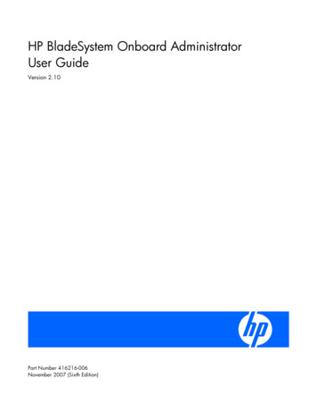
Controlling componentsThe BladeSystem Onboard Administrator uses embedded management interfaces to provide detailedinformation and health status for all bays in the enclosure (Figure 4). The BladeSystem OnboardAdministrator also reports firmware versions for most components in the enclosure and can be used toupdate those components.Figure 4. Management communications between the BladeSystem Onboard Administrator and other componentsin an HP BladeSystem c7000 Enclosurec7000 internal management interfacesThe BladeSystem Onboard Administrator monitors and communicates with several hardwareinterfaces to each bay in the c7000 enclosure. The management hardware interfaces include uniquepresence pins, Inter-Integrated Circuit (I2C), serial, and Ethernet connections. These managementinterface connections are completely isolated from the server blade connections to interconnectmodules.c7000 external management interfacesEach c7000 enclosure has several external management interfaces connected to the BladeSystemOnboard Administrator as shown in Figure 4. The primary external management interface is themanagement port for each BladeSystem Onboard Administrator, which is an RJ-45 jack providingEthernet communications not only to each BladeSystem Onboard Administrator, but also to everydevice or interconnect bay with a management processor. This includes ProLiant OnboardAdministrator (iLO 2) communication for the server blades and any interconnect module using thec-Class embedded Ethernet management network, such as Virtual Connect Manager. For redundantBladeSystem Onboard Administrators, both BladeSystem Onboard Administrator management ports7
are connected to the management network, providing redundant management network connections toeach enclosure.A serial port on each BladeSystem Onboard Administrator module provides full out-of-band CLIaccess to the BladeSystem Onboard Administrator and is used for BladeSystem OnboardAdministrator firmware flash recovery. USB ports on the BladeSystem Onboard Administrator areused to connect DVD drives to support the DVD feature in the c7000 enclosure. All c-Class enclosuressupport two enclosure link connectors that provide private communications between enclosures linkedwith CAT5 cable. In addition, the enclosure link-up connector provides an enclosure service port fortemporarily connecting a laptop PC to any of the linked enclosure BladeSystem OnboardAdministrators for local diagnostics and debugging.Updating firmwareThe BladeSystem Onboard Administrator manages firmware updates for the enclosure’s managementdevices. Updating server blade firmware including server BIOS, NIC and mezzanine BIOS, andProLiant Onboard Administrator (iLO 2) is possible using HP System Update Manager or the bladefirmware update maintenance CD. These utilities can be connected to all the server blades in theenclosure using the BladeSystem Onboard Administrator enclosure DVD feature. When the activeBladeSystem Onboard Administrator detects an external USB DVD drive plugged into the USB port, itscans the DVD drive for a CD or DVD disk. This disk can then be connected to one or more serverblades at the same time using the BladeSystem Onboard Administrator GUI, CLI, or Insight Display.Redundant enclosure managementRedundant enclosure management is an optional feature of the c7000. It requires installing a secondBladeSystem Onboard Administrator module in the c7000 enclosure to act as a completely redundantcontroller in an active-standby mode. Using redundant modules in the c7000 enclosure providescomplete fault tolerance. The redundancy logic is based on a continuous heartbeat between the twomodules over a dedicated serial connection (Figure 4). If the period between heartbeats exceeds atimeout, the standby module automatically takes control of the enclosure and becomes the activeBladeSystem Onboard Administrator.User interfaces for the BladeSystem Onboard AdministratorThree user interfaces to the BladeSystem Onboard Administrator allow control and provideinformation about the enclosure and installed components:Web browser GUIScriptable CLIInsight Display diagnostic LCD panelAdditionally, the BladeSystem Onboard Administrator with KVM adds the ability to directly connect aKVM switch through the VGA port. Remote network access to the GUI and CLI is available through themanagement Ethernet port. A serial port is available for local CLI access and flash recovery. Thec-Class enclosure link-up port is also available as the service port for temporary local Ethernet accessto the BladeSystem Onboard Administrators and devices in linked enclosures. Insight Display isaccessed directly through the buttons on the display or remotely through the GUI.SecurityUser authentication maintains security for all user interfaces. User accounts created in the BladeSystemOnboard Administrator define three user privilege levels and the component bays to which each levelis granted access. The BladeSystem Onboard Administrator stores the passwords for local useraccounts and can be configured to use Lightweight Directory Access Protocol (LDAP) authentication foruser group accounts.8
Role-based user accountsThe BladeSystem Onboard Administrator provides configurable user accounts that can providecomplete isolation of multiple administrative roles such as server, LAN, and SAN. User accounts areconfigured with specific device bay or interconnect bay permissions and one of three privilege levels:administrator, operator, or user. An account with administrator privileges including BladeSystemOnboard Administrator bay permission can create or edit all user accounts on an enclosure. Operatorprivileges allow full information access and control of permitted bays. User privileges allowinformation access but no control capability.The BladeSystem Onboard Administrator requires user login to the web GUI or CLI with an account IDand password. For a local account, the password is stored on the BladeSystem OnboardAdministrator. For an LDAP account, the BladeSystem Onboard Administrator contacts the definedLDAP server to check the user credentials. Two-factor authentication allows even tighter security for theuser management session to the BladeSystem Onboard Administrator.Enclosure linkingRather than requiring separate logins to access multiple management processors within eachenclosure, the BladeSystem Onboard Administrator allows single point access. Thus, an administratorcan use single sign-on to log in to a single BladeSystem Onboard Administrator and use the web GUIto graphically view and manage the HP BladeSystem c-Class components in up to seven linkedenclosures. For example, an IT administrator could automatically propagate managementcommands—such as changing the enclosure power mode—throughout the linked enclosures.The c7000 enclosure contains two enclosure link ports to allow any active BladeSystem OnboardAdministrator module to access linked enclosures. On a standalone enclosure or upper enclosure in aseries of linked enclosures, the upper enclosure link-up port functions as a service port for temporaryconnection to a PC with a CAT5 patch cable. It provides quick access to any BladeSystem OnboardAdministrator module, ProLiant Onboard Administrator (iLO 2), or interconnect module with Ethernetmanagement ability.The enclosure link-down port connects to the enclosure link-up port on the enclosure below it. Linkingthe enclosures enables the rack technician to access all the enclosures through the openlink-up/service port. If more c-Class enclosures are added to the rack, they can be linked through theopen enclosure link-up port on the upper enclosure or the link-down port on the bottom enclosure.NOTEThe linked enclosures will enforce a common rack name on allthe linked enclosures unless different rack names are establishedprior to linking the enclosures and not changed after linking theenclosures.IMPORTANTThe HP BladeSystem c-Class Enclosure link ports are notcompatible with the HP BladeSystem p-Class Enclosure linkports.9
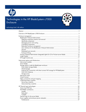
ProLiant Onboard Administrator (Integrated Lights-Out 2) for ProLiantserver bladesHP BladeSystem c-Class employs ProLiant Onboard Administrator (iLO 2) to configure, update, andoperate individual server blades remotely. The c7000 enclosure includes an Ethernet managementnetwork to aggregate all ProLiant Onboard Administrator (iLO 2) management communicationsacross the entire enclosure. This management network connects ProLiant Onboard Administrator(iLO 2) processors to the BladeSystem Onboard Administrator through the BladeSystem OnboardAdministrator tray, as illustrated in Figure 4. The BladeSystem Onboard Administrator provides directaccess to each ProLiant Onboard Administrator (iLO 2) through the enclosure management network.The BladeSystem Onboard Administrator uses this network to manage pooled enclosure power andcooling, which results in substantial energy savings over the same number of individual rack-mountedservers.Insight DisplayThe Insight Display, Figure 5, is an ever-ready, enclosure-mounted information exchange device withaccess to all BladeSystem Onboard Administrator setup, management, and troubleshooting features. Itis a quick and easy-to-use device that allows technicians to initially configure the enclosure. It alsoprovides information about the health and operation of the enclosure. The Insight Display is effectivemechanically because it is large enough to see ample information, and it can slide back and forth toallow access to the power supplies.Figure 5. Insight Display on the c7000 enclosureWhen the c7000 enclosure is initially powered on, the enclosure UID LED and the Insight Display areilluminated blue to identify the enclosure being configured. The Insight Display automatically launchesan installation wizard to guide the user through the configuration process. After the enclosure isconfigured, the Insight Display verifies that there are no installation or configuration errors. TheInstallation Wizard turns off the enclosure UID when the installation is complete.When an error or alert condition is detected, the Insight Display Health Summary screen displays thetotal number of error conditions and their locations in the order of error severity (Figure 6). Failurealerts (if any exist) display first and then caution alerts. Providing this level of diagnostic informationfor each enclosure dramatically shortens setup, repair, and troubleshooting time.For example, in Figure 6 the Insight Display diagnostic screen reports an error in power supply bay5. The Health Summary screen shows the power supply in bay 5 as red. When the technician selectsView Alert, the Device Error Summary screen indicates the same condition. The Device Error detail inthe third screen shows that the power supply in bay 5 has failed. When the technician selects fix on10
the Device Error screen, suggestions for corrective action appear (in this case an animation indicatingthe proper positions when replacing power supplies in the c7000 enclosure).Figure 6. BladeSystem c-Class Insight Display diagnostic screens indicating an error and suggested correctiveactionMore information about the Insight Display is available in the technology brief titled ―Managing theHP BladeSystem rt/SupportManual/c00814176/c00814176.pdf.HP Insight Control suiteHP Insight Control suite delivers essential management for HP BladeSystem lifecycles, includingproactive health management, lights out remote control, optimization of power usage, rapid serverdeployment, performance analysis, vulnerability scanning and patch management, and virtualmachine management.The software is delivered on DVD media. It includes an integrated installer to rapidly and consistentlydeploy and configure HP Systems Insight Manager (HP SIM) and essential infrastructure managementsoftware. The integrated installer includes a wizard-based interface that presents a series ofconfiguration questions. When the user has answered the configuration questions, each of theselected components will be deployed in a single process. The HP Insight Software Advisor checks toensure that the host central management server meets all installation pre-requites before installation.When installation is complete, the Insight Software Update Utility will check for available softwareupdates.HP Insight Control suite installs and licenses the following components for use:HP Systems Insight ManagerHP iLO Advanced for BladeSystemHP Insight Power ManagerHP Insight Rapid Deployment PackHP Insight Performance Manager moduleHP Insight Vulnerability and Patch Manager moduleHP Insight Virtual Machine Manager softwareHP Insight Control suite integrates with leading enterprise management platforms through industrystandards. It includes one year of 24 x 7 HP Software Technical Support and Update Service.11
Interconnect options and infrastructureA key component of the c7000 enclosure is the I/O infrastructure—essentially, a NonStop signalmidplane that provides the internal wiring between the server or storage blades and the interconnectmodules. The NonStop signal midplane is an entirely passive board that takes advantage ofserializer/deserializer (SerDes) technology to support multiple protocols and provide point-to-pointconnectivity between device bays and interconnect bays. The term passive means there are no activeelectrical components on the board. On one side of the board are the sixteen connectors for theserver/storage blades. Internal traces link them to the eight connectors on the other side of the boardfor the interconnect modules (Figure 7).The signal midpla
ProLiant Onboard Administrator (iLO 2) is possible using HP System Update Manager or the blade firmware update maintenance CD. These utilities can be connected to all the serve