Transcription
1
FOREWORDBackgroundIn 1971, after the San Fernando earthquake when two VA buildings collapsed, VA beganto undertake a full seismic safety program. Title 38 - United States Code, section 8105required the Secretary to assure that each medical facility constructed or altered shall beof construction that is resistant to fire, earthquake, and other natural disasters. Thisinitiated the creation of the Secretary’s Advisory Committee on Structural Safety of VAFacilities, which formally approved in 1975 the original VA Seismic Design document, H08-8, Earthquake Resistant Design Requirements for VA Facilities. These requirementswere developed with the concept that all VA Essential Facilities must remain in operationafter an earthquake and were far in advance of National Codes.This document is periodically updated and revised. The revision of H-08-8 to H-18-8 in1995 was a major rewrite to bring VA seismic design requirements more in line with theupdated national model codes. Further updates/revisions of minor nature were made in1997, 1998, 2000, 2002, 2003, 2005, 2006, 2008, 2010, and 2011.Current Revision Highlights: Reference of ASCE 396 changed to FEMA 396 Modified definition of Ancillary Facilities slightly to define them as non-essential. Modified sections 3.7 to preclude exemption of non-structural elements in low seismicityand emphasize following section 4.0.Note: A vertical bar is placed to the right of the revised sections.Lloyd H. SiegelAssociate Executive DirectorOffice of Facilities PlanningAugust 20132
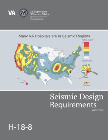
TABLE OF CONTENTS1.0 Definitions . 42.0 General . 63.0 Modifications to Requirements of IBC for NewCritical and Essential Facilities . 84.0 Elements of Structures, Nonstructural Components,and Equipment Supported by Structures . 115.0 Site Data for Critical and Essential Facilities . 126.0 Commentary . 147.0 Tables . 168.0 Seismicity Map with Department of Veterans Affairs Medical Centers . 253
1.0 DEFINITIONS1.1 ASCE/SEI 41–06: Seismic Rehabilitation of Existing Buildings, American Society ofCivil Engineers.1.2 AISC 341: Seismic Provisions for Structural Steel Buildings, including SupplementNo. 1 dated 2006, American Institute of Steel Construction.1.3 ASCE 7: Minimum Design Loads for Buildings and Other Structures, AmericanSociety of Civil Engineers, Latest Edition1.4 ASCE 31- 02: Seismic Evaluation of Existing Buildings, American Society of CivilEngineers.1.5 FEMA 396: Incremental Seismic Rehabilitation of Hospital Buildings, AmericanSociety of Civil Engineers.1.6 Category of Facilities:a) Critical Facilities: Buildings that are required to remain functional after anearthquake or other natural disaster such as hurricane, tornado, etc. Thesefacilities include, but are not limited to, the occupancy categories listed as CriticalFacilities in Table 1, and they shall be assigned to IBC Occupancy Category IV.b) Essential Facilities: Buildings that must remain operational with minor repairsafter an earthquake or other natural disaster such as hurricane, tornado, etc.These facilities include, but are not limited to occupancy categories listed asEssential Facilities in Table 2, and they shall be assigned to IBC OccupancyCategory III.c) Ancillary Facilities: These facilities include, but are not limited to, theoccupancy categories listed as Ancillary Facilities in Table 3. All ancillary facilitiesshall be designated as non-essential facilities and shall be assigned to IBCOccupancy Category II.1.7 IBC: International Building Code, Latest Edition.1.8 Occupancy Category: A category used to determine earthquake design loadsbased on the nature of the occupancy.1.9 OSHPD: Office of Statewide Health Planning & Development, State of California1.10 Seismic Design Category: A classification assigned to a structure based on itsoccupancy category and the severity of the design earthquake ground motion atthe site (as defined in IBC and ASCE 7).4
1.12 SeismicityRegion of SeismicityVery HighHighModerate – HighModerate – LowLowSS 1.250g 1.250g 0.750g 0.750g 0.350g 0.350g 0.250g 0.250gS1 0.500g 0.500g 0.300g 0.300g 0.140g 0.140g 0.100g 0.100gNote: Values for SS and S1 at all VA sites are given in Table 41.13 Soft Story & Extreme Soft Story: As defined in ASCE 7, Table 12.3-2.1.14 Spectral Response Acceleration: A parameter used to characterize theanticipated earthquake shaking at a given site. (Table 4)Ss: Spectral acceleration parameter at short periods corresponding to the mappedmaximum considered earthquake.S1: Spectral acceleration parameter at a period of 1 sec corresponding to themapped maximum considered earthquake.5
2.0 GENERALThese requirements cover all VA facilities including those of National CemeteryAdministration, Veterans Benefits Administration, and Veterans HealthAdministration.2.1 New Critical and Essential FacilitiesAll new Critical and Essential Facilities shall be designed and constructed in fullcompliance with the earthquake design and detailing requirements of IBC asmodified in these provisions. Critical Facilities shall be assigned IBC OccupancyCategory IV and Essential Facilities shall be assigned IBC Occupancy Category III.These buildings are intended to remain operational after an earthquake or othernatural disaster such as tornado or hurricane as defined in ASCE 7, Section 1.5.2.2 New Ancillary FacilitiesAll new Ancillary Facilities shall be designed and constructed in full compliancewith the earthquake design and detailing requirements of IBC with no additionalmodifications. Ancillary Facilities shall be assigned to Occupancy Category II asdefined in ASCE 7, Section 1.5.2.3 Existing Facilities - Evaluationa.A seismic evaluation shall be conducted for existing facilities in areas ofModerate High, High, and Very High Seismicity that meet one or more of thefollowing criteria:i. Facilities selected for renovation as part of a VA classified Major Projectii. Facilities selected for renovation where the area of renovation is greaterthan 50% of the total areaiii A project is planned which significantly extends the building’s useful lifethrough alterations or repairs which total more than 30% of thereplacement value of the facility.iv. Facilities under consideration by VA for purchase or leaseb.Existing Critical and Essential Facilities shall be evaluated using theprocedures in ASCE 31-02 for the Immediate Occupancy Performance Level.c.Existing Ancillary Facilities shall be evaluated using the procedures in ASCE31-02 for the Life Safety Performance Level.2.4 Existing Facilities – Rehabilitationa. All Critical and Essential Existing Facilities shall be rehabilitated using nonlinearstatic procedures described in ASCE 41 to achieve the following rehabilitationobjectives.6
i. Immediate occupancy performance level at BSE-1 (Basic Safety EarthquakeLevel 1, Earthquake Hazard Level having a probability of exceedance of 10percent in 50 years) as defined in ASCE 41.ii. Collapse Prevention performance level at BSE-2 (Basic Safety EarthquakeLevel 2, Earthquake Hazard Level having a probability of exceedance of 2percent in 50 years) as defined in ASCE 41.b. All Ancillary Facilities shall be rehabilitated using nonlinear static proceduresdescribed in ASCE 41 using the requirements to achieve Basic Safety Objectives.2.5 Existing Facilities Rehabilitation – Alternative ApproachAn alternative approach may be permitted on a case-by-case basis upon approvalby the Office of Construction & Facilities Management (CFM) for Critical andEssential Facilities to be strengthened according to procedures in ASCE 41.2.6 Spectral Response AccelerationsThe selection of Seismic Design Category for use in the design and analysis ofall new and existing facilities shall be based on the spectral responseaccelerations shown in Table 4 after adjustment for site class effects asspecified in ASCE 7. For the design of buildings in Seismic Design Category A,use ASCE 7 section 11.7. For all other Seismic Design Categories (B – F), useASCE 7Chapter 12: Seismic Design Requirements for Building Structures.7
3.0 MODIFICATIONS TO THE REQUIREMENTS OF IBC FOR NEW CRITICAL ANDESSENTIAL FACILITIES ASSIGNED TO HIGH SEISMIC DESIGNCATEGORIES3.1 Structural Irregularities (ASCE 7, Section 12.3.3)For structures assigned to Seismic Design Categories D, E, or F, the followingtypes of irregularities as defined by ASCE 7 Table 12.3-1 & 2 are not allowed:a.b.c.d.Stiffness irregularity – Soft StoryStiffness irregularity – Extreme Soft StoryWeight (mass) irregularityVertical geometric irregularity3.2 Seismic-force-resisting-systems (ASCE 7, Table 12.2-1)The following structural systems are permitted for new Critical and EssentialFacilities assigned to Seismic Design Categories D, E, or F.a. Building Frame Systemsi. Steel eccentrically braced frames (EBF) moment resisting connections atcolumns away from linksii. Special reinforced concrete shear walls (Building Frame)iii. Special reinforced masonry shear walls (Building Frame)iv. Special steel concentrically braced framesv. Light frame walls with shear panels-wood structural panels/sheet steelpanels (Building Frame) for structures two stories or lessvi. Buckling-restrained braced frames, moment-resisting beam-columnconnectionsb. Moment-Resisting Frame Systems, if approved by VA.i. Special steel moment-resisting frames (SMRF)ii. Special reinforced concrete moment-resisting framesc. Dual Systemsi. Special reinforced concrete shear walls with SMRFii. Special reinforced masonry shear walls with SMRFiii. Steel EBF with SMRFiv. Special steel concentrically braced frame with SMRFv. Buckling-restrained braced frameOther structural systems as permitted by the IBC for Seismic Design Categories D,E or F, including ones that employ seismic isolation and seismic damping systemsare permitted subject to written approval by the VA.8
3.3 Special Provisions for structures assigned to Seismic Design Categories D,E, or F.The provisions of this section shall apply to all new Critical and Essential Facilities.a. Bay spacing essentially shall be equal and uniform throughout.b. Transfer beams or trusses supporting upper level columns shall not be usedunless permitted on a case by case basis by VA.c. Seismic joints shall be avoided, in so far as possible. When required, they shallbe specifically identified in the schematic design phase of the project andapproved by VA, subject to the following provisions:1. Seismic joints shall be properly detailed on the working drawings;2. Seismic joints shall be sized based on the maximum expecteddisplacements, considering the effects of story drift, diaphragmdisplacements and rotations, and a realistic approximation of elementsection properties. For materials designed considering the ultimate limitstate, such as concrete, the stiffness representative of this state shall beused. Seismic separations shall be 125% of the separation required byASCE 7; and3. Adjacent structures that are not integral with an existing structure shall beseparated by not less than 2 inches per story.3.4 Limitations on Reinforced Concrete StructuresThe provisions of this section shall apply to all new Critical and Essential Facilitiesassigned to Seismic Design Categories D, E, or F.a. Prestressed concrete structural members, including pre-tensioned and posttensioned members, and precast elements such as tilt-up wall panels, andprecast beam and column elements shall not be used to resist seismic forces.b. Lightweight concrete shall not be used in structural members resistingearthquake forces, except in concrete floors and roof slabs used as diaphragmelements to distribute earthquake forces to vertical lateral-load resistingelements.9
3.5 Limitations on Steel StructuresThe provisions of this section shall apply to all new Critical and Essential Facilitiesassigned to Seismic Design Categories D, E, or F.a. Special steel moment resisting frame system shall be in compliance withSection 9 of AISC 341.b. Steel eccentrically braced systems shall be subject to the following specialprovisions:1. Connections of non-structural elements shall not be located in the vicinity ofEBF link beams. Non-structural elements include, but are not limited to, precast panel connections, elevator guide rail supports, stairs, and pipesupports, etc.3.6 Story Drift LimitationsThe calculated story drift for the construction of all new Critical and EssentialFacilities assigned to Seismic Design Categories D, E, or F shall not exceed 50%of the values allowed by ASCE 7.3.7 Exemptionsa. No action regarding seismic rehabilitation of the seismic force resisting systemof existing buildings need be undertaken in regions of moderate-low and lowseismicityb. Non-structural components shall comply with the requirements of section 4.0.10
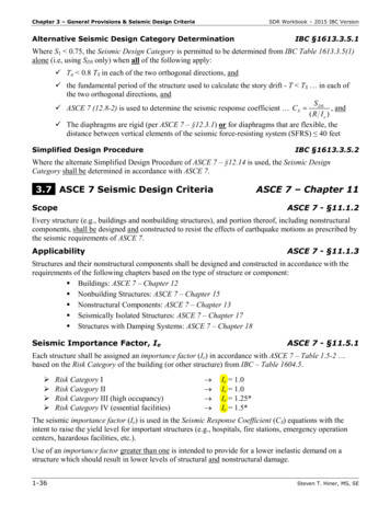
4.0 ELEMENTS OF STRUCTURES, NONSTRUCTURAL COMPONENTS, ANDEQUIPMENT SUPPORTED BY STRUCTURES FOR CRITICAL ANDESSENTIAL FACILITIES4.1 1In structures assigned to Seismic Design Category C, D, E, or F, permanentequipment and nonstructural components and their attachments, and the structuresupported attachments of permanent equipment shall be designed to resist totaldesign forces prescribed in ASCE 7, Chapter 13 as modified by this document.Exceptions: Seismic restraint may be omitted for the following installations:a. Gas and medical piping less than one inch inside diameter;b. Piping in boiler and mechanical equipment rooms less than 1 ¼ inch insidediameter;c. All other piping less than 2 ½ inch inside diameter except for automatic firesuppression systems;d. All electrical conduits, less than 2 ½ inch inside diameter;e. All rectangular air handling ducts less than six square feet in cross sectionalarea;f. All round air handling ducts less than 28 inches in diameter;g. All ducts suspended by hangers 12 inches or less in length from the top of theduct to the bottom of the support for the hanger;h. Equipment weighing less than 400 lbs, supported and attached directly on thefloor; andi.Equipment weighing less than 20 lbs suspended from the roof or floor or hungfrom the wall.4.2 In structures assigned to Seismic Design Category C, D, E, or F, permanentequipment and components are to have Special Seismic Certification inaccordance with requirements of section 13.2.2 of ASCE 7 except for equipmentand components that are considered rugged as listed in section 2.2 of OSHPDcode application notice CAN No. 2-1708A.5, and shall comply with section 13.2.6of ASCE 7.11
5.0 SITE DATA FOR CRITICAL AND ESSENTIAL FACILITIES5.1 New and Existing FacilitiesGeologic hazards and site-specific ground-response reports shall be required forall proposed construction of new Critical and Essential Facilities assigned toSeismic Design Category C, D, E, or F and for all proposed seismic rehabilitationof existing Critical and Essential Facilities in areas of Moderate High, High, andVery High Seismicity.Except in regions of low seismicity, the geotechnical investigation shall useappropriate methods to allow the most accurate evaluation of the site class inaccordance with Chapters 20 and 21 of ASCE 7, including field shear wavevelocity measurements.5.2 Geologic Hazards ReportThe purpose of the geologic hazards report shall be to identify potential geologicand seismic conditions that require detailed evaluation, and may require mitigationby the project. The report shall contain data that provide an assessment of thenature of the site and potential for earthquake damage based on preliminaryinvestigations of the regional and site geology, subsurface conditions and thepotential seismic shaking. The engineering geologic report shall not contain designcriteria, but shall contain basic data to be used for a preliminary earthquakeengineering evaluation of the project. The basis for seismic assessment in geologichazards reports must be stated clearly.The report shall include, but shall not be limited to the following:a. Geologic investigation;b. Identification of any known active and potentially active faults, both regionaland local, including estimates of the peak ground accelerations that could occurat the site; andc. Evaluation of any slope stability problems at or near the site, liquefactionpotential and settlement potential of the building site.VA shall approve the engineering geologic hazard report prior to the preparation ofthe geotechnical report.12
5.3 Site-Specific Ground-Response ReportThe site-specific ground-response report shall present a detailed characterizationof earthquake ground motions for the site. The characteristics of the expectedstrong ground motion to be used in design shall be determined by site evaluationstudies based on geological and seismological characteristics of the site, includingdata given in the engineering geologic hazards report. The estimates should bederived by accepted methods of seismological practice, including Next GenerationAttenuation (NGA) relationships where applicable, and fully documented in theground response report. The level of ground motions to be developed shall bedetermined using the procedures in Chapter 21 of ASCE 7.VA shall approve the site-specific ground response report prior to its adoption forproject design.13
6.0 COMMENTARYSection 1.0Section 1.2: Critical and Essential Facilities are those where most operations andfunctions must be able to resume immediately, while repair is required to restoresome non-essential services due to a limited amount of seismic damage.Section 2.0Section 2.1: The seismic design requirements in the previous edition of H-18-8 didnot distinguish between the Critical and Essential categories. This has now beenseparated and has different design requirements.Section 3.0Section 3.1: The design engineer shall provide multiple lines of resistance whenselecting a lateral force-resisting configuration. Redundancy of frame lines isintended to avoid concentration of seismic force demands in the structure and/orfoundation system. Lines of lateral force resistance shall be located at major areasof plan irregularity such as reentrant corners.Section 3.2The permitted structural systems listed in Section 3.2 are chosen to provide costeffective and reliable seismic performance. Proposals to obtain written approvalfor other structural systems shall demonstrate the value of those systems, relativeto the permitted systems, considering (a) initial construction and maintenancecosts, (b) requirements for bracing non-structural components and buildingcontents, (c) risk of economic losses and disruption to hospital functions due toearthquakes and (d) other demonstrable benefits.”Section 3.3.cBecause seismic joints have a serious impact on exterior siding, floor joints, andinterior construction and utilities, they should be avoided if at all possible.14
Section 5.0Site class is used to determine the values of short-period and 1-second designspectral accelerations, SDS and SD1 that define Seismic Design Category inaccordance with ASCE-7. Except in regions of low seismicity, an accurateevaluation of site class is to be made in accordance with Chapter 20 and Chapter21 of ASCE 7 and is to be presented in the geotechnical evaluation report. Fieldshear wave velocity measurements are typically expected to provide the mostreliable basis for an accurate evaluation of site class.Although site-specific studies exist for most of VA’s Critical sites, the intent of thisprovision is to update those studies (done in mid-seventies) for all proposedconstruction of new Critical and Essential Facilities assigned to moderate or highseismic design categories and all existing Critical and Essential Facilities selectedfor full seismic rehabilitation in areas of Moderate High, High, and Very HighSeismicity.New site-specific studies for VA facilities are to consider up-to-date information onthe attenuation of earthquake ground motions with distance from the earthquakesource, and other relevant seismologic and geologic information. Researchsponsored by the Pacific Earthquake Engineering Research Center has led tosignificantly improved procedures to estimate attenuation of earthquake motions,and culminated with publication in 2008 of so-called Next Generation Attenuation(NGA) relationships for plate-boundary tectonic regimes dominated by crustalfaults, such as the Western United States. It is the intent of VA requirements thatnew site-specific studies for VA facilities take advantage of those improvedprocedures and other pertinent published information on earthquake groundmotion estimation, in accordance with the state of practice for the seismic design ofbuildings.The standard practice of preparing a geotechnical report containing foundationrecommendations, soil-bearing values, results of any necessary soil borings, etc.,is still required for all VA projects.15
[VA Facilities Occupancy Categories]Table 1: Critical FacilitiesTable 2: Essential FacilitiesOccupancy Sub-nameOccupancy Sub-nameAcute CareAmbulatory Care/ Outpatient ClinicAnimal FacilityBoiler PlantsCommunications CenterEmergency Command CenterEmergency GeneratorFire/Police StationHazardous Material StorageHospitalInformation TechnologyMedical Gas StorageMedical Research/RecordsNational Continuity of Operation CenterSecurity & Law EnforcementWater Tower, Utility Supply Storage StructureConsolidate Mail-Out PharmacyDieteticsDomiciliaryDrug/Alcohol RehabilitationLong Term CareMedical Equipment StorageMental Health - InpatientPsychiatric Care FacilityRehabilitation MedicineTable 3: Ancillary FacilitiesOccupancy Sub-nameAccessory Non-Building StructureAuditoriumBiomedical Eng. (equip. & wheelchair repair)Canteen-CafeteriaCanteen-Retail StoreCemetery BuildingChapelChild CareClinical Service Administration OfficeCommunity-Based Outpatient ClinicConnecting Corridor-Concourse, and BridgeCredit UnionGeneral Administration OfficeGreenhouseQuarter (Residential)LaundryLibrary/MuseumMaintenance Facility (Shops)Maintenance Storage (Equipment)Materials Management StorageOfficeSchoolParking GaragePlant OutbuildingPost OfficeRecreationalStudent HousingTemporary BuildingToilets (Outhouse)Training, EducationVeterans ServicesWarehouseWaste Management (Incinerator & Recycle)Waste StorageNote: The Critical, Essential and Ancillary Facilities Tables are developed to keep in linewith three occupancy categories listed in IBC.16
Table 4Spectral Response Accelerations at VA FacilitiesSiteAbraham driaAllen ParkAltonAltoonaAmarilloAmerican LakeAnchorageAnn sta (Lenwood)Balls BluffBaltimoreBaltimoreBaltimore/Loch RavenBarrancasBataviaBathBathBaton RougeBattle CreekBay PinesBay PinesBeaufortBeckleyBedfordBeverlyBig SpringBiloxiBiloxiBirminghamBlack HillsMed CenterNumberStateSs (new)S1 LMHMHLLLLLMLLLLLLLMHMLMLMLLLLMLLNote: Values of Ss & S1 have been obtained from the design maps of Chapter 22of ASCE 7.17
Table 4 (continued)Spectral Response Accelerations at VA xBrooklynBuffaloButlerCalvertonCamp ButlerCamp NelsonCanandaiguaCastle PointCave HillCharlestonChattanoogaCheyenneChicago (Lakeside)Chicago (Westside)ChillicotheCincinnatiCity PointClarksburgCleveland/BrecksvilleCleveland/Wade ParkCoatesvilleCold HarborColumbiaColumbiaCorinthCrown HillCulpeperCypress HillsDallasDallas/Fort enverMed CenterNumberStateSs (new)S1 MLVHMHLLLLLLLLLMLLLMHMHLLMHLLLLLLLLLNote: Values of Ss & S1 have been obtained from the design maps of Chapter 22of ASCE 7.18
Table 4 (continued)Spectral Response Accelerations at VA FacilitiesSiteDes MoinesDetroitDublinDurhamEagle PointEast OrangeEl inn's PointFlorenceFloridaFort BayardFort BlissFort CusterFort GibsonFort HarrisonFort HarrisonFort HowardFort LeavenworthFort LoganFort LyonFort LyonFort McPhersonFort MeadeFort MeadeFort MitchellFort RichardsonFort RosecransFort Sam HoustonFort ScottFort SillFort SmithFort SnellingFort ThomasFort WayneFresnoGainesvilleGlendaleMed CenterNumberStateSs (new)S1 LLMHLLNote: Values of Ss & S1 have been obtained from the design maps of Chapter 22of ASCE 7.19
Table 4 (continued)Spectral Response Accelerations at VA FacilitiesSiteGolden GateGraftonGrand IslandGrand JunctionGulfportHamptonHamptonHampton (VAMC)HinesHines VBA**HonoluluHot SpringsHot SpringsHoustonHoustonHouston VBAHuntingtonIndianapolisIndianapolis (CS Rd)Indiantown GapIowa CityIron MountainJacksonJackson VBAJefferson BarracksJefferson CityKansas CityKeokukKerrvilleKerrvilleKnoxvilleKnoxvilleLake CityLas Lexington (CD)Lexington (LD)Med CenterNumberStateSs (new)S1 te: Values of Ss & S1 have been obtained from the design maps of Chapter 22of ASCE 7.20
Table 4 (continued)Spectral Response Accelerations at VA FacilitiesSiteLincolnLittle RockLittle RockLivermoreLoma LindaLong BeachLong IslandLos AngelesLos AngelesLoudon settsMcClellanMemphisMemphisMenlo ParkMiamiMiles CityMill SpringsMilwaukee (Wood)MinneapolisMobileMontgomeryMontgomery VBAMontroseMound CityMountain HomeMountain HomeMurfreesboroMuskogeeNashvilleNashvilleMed CenterNumberStateSs (new)S1 MHVHVHVHLLLLLLLLMLVHMHMHMLLMLMLNote: Values of Ss & S1 have been obtained from the design maps of Chapter 22of ASCE 7.21
Table 4 (continued)Spectral Response Accelerations at VA FacilitiesSiteNatchezNCA Operations SupportNew AlbanyNew BernNew OrleansNew YorkNewingtonNMCA**NMCPNorth ChicagoNorth Little RockNorthamptonNorthportOklahoma CityOmahaOrlandoPalo AltoPerry PointPhiladelphiaPhiladelphiaPhoenixPittsburgh (HD)Pittsburgh (UD)Poplar BluffPort incyRaleighRenoRichmondRichmond**RiversideRock
4 1.0 DEFINITIONS 1.1 ASCE/SEI 41-06: Seismic Rehabilitation of Existing Buildings, American Society of Civil Engineers. 1.2 AISC 341: Seismic Provisions for Structural Steel Buildings, including Supplement No. 1 dated 2006, American Institute of Steel Construction. 1.3 ASCE 7: Minimum Design Loads for Buildings and Other Structures, American
