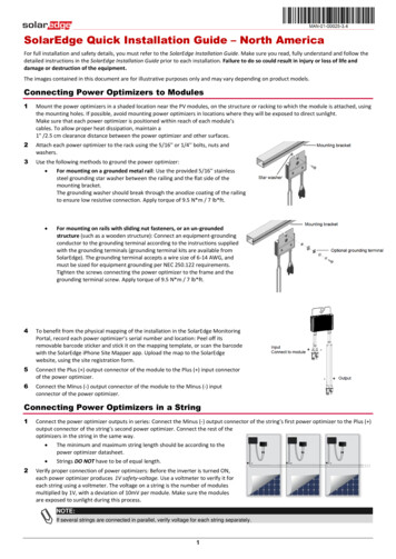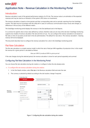
Transcription
DisclaimersDisclaimersImportant NoticeCopyright SolarEdge Technologies Inc. All rights reserved.No part of this document may be reproduced, stored in a retrieval system or transmitted, in any form orby any means, electronic, mechanical, photographic, magnetic or otherwise, without the prior writtenpermission of SolarEdge Inc.The material furnished in this document is believed to be accurate and reliable. However, SolarEdgeassumes no responsibility for the use of this material. SolarEdge reserves the right to make changes to thematerial at any time and without notice. You may refer to the SolarEdge web site (www.solaredge.us) forthe most updated version of this and other documents.All company and brand products and service names are trademarks or registered trademarks of theirrespective holders.Patent marking notice: see http://www.solaredge.us/groups/patentThe general terms and conditions of purchase of SolarEdge products shall apply.The content of these documents is continually reviewed and amended, where necessary. However,discrepancies cannot be excluded. No guarantee is made for the completeness of these documents.The images contained in this document are for illustrative purposes only and may vary depending onproduct models.FCC ComplianceThis equipment has been tested and found to comply with the limits for a Class B digital device, pursuantto part 15 of the FCC Rules. These limits are designed to provide reasonable protection against harmfulinterference in a residential installation. This equipment generates, uses and can radiate radio frequencyenergy and, if not installed and used in accordance with the instructions, may cause harmful interferenceto radio communications. However, there is no guarantee that interference will not occur in a particularinstallation. If this equipment does cause harmful interference to radio or television reception, which canbe determined by turning the equipment OFF and ON, you are encouraged to try to correct theinterference by one or more of the following measures:Reorient or relocate the receiving antenna.Increase the separation between the equipment and the receiver (and its antenna).Connect the equipment into an outlet on a circuit different from that to which the receiver isconnected.Consult the dealer or an experienced radio/TV technician for help. Changes or modifications not expressly approved by the party responsible for compliance may void theuser’s authority to operate the equipment.SolarEdge Installation Guide – MAN-01-00002-3.21
Support and Contact InformationSupport and Contact InformationIf you have technical queries concerning our products, please contact us:USA and Canada: 1 (0) 877 360 5292Worldwide: 972 (0) 73 240-3118Fax: 1 (0) 530 273-2769Email to:support@solaredge.usBefore contact, make sure to have the following information at hand:Inverter and power optimizer model numbersSerial number of the product in questionThe error indicated on the inverter screen or on the SolarEdge monitoring portal, if there is such anindicationSystem configuration information, including the type and number of modules connected and thenumber and length of stringsThe communication method to the SolarEdge monitoring portal, if the site is connectedInverter software version as appears in the ID status screen (see page 52). 2SolarEdge Installation Guide – MAN-01-00002-3.2
Table of ContentsTable of ContentsDisclaimers . 1Important Notice .1FCC Compliance .1Support and Contact Information . 2Table of Contents . 3HANDLING AND SAFETY INSTRUCTIONS . 6SAFETY SYMBOLS .6IMPORTANT SAFETY INSTRUCTIONS .7Chapter 1: Introducing the SolarEdge System . 9System Overview .9SolarEdge Power Optimizer . 9SolarEdge Inverter with Safety Switch . 9SolarEdge Monitoring Portal . 9Supported AC Grids .10Grids Supported by the Single Phase Inverters . 10Grids Supported by the Three Phase Inverters . 11Installation Procedure .12Installation Equipment List .13Inverter Transport and Storage .13Chapter 2: Installing the Power Optimizers. 14Safety .14Package Contents .15Installation Guidelines .15Step 1, Mounting and Grounding the Power Optimizers .16Step 2, Connecting a Module to a Power Optimizer .18Step 3, Connecting Power Optimizers in Strings .19Step 4, Verifying Proper Power Optimizer Connection .19Chapter 3: Installing the Inverter . 21Inverter Package Contents .21Identifying the Inverter .21Inverter Interfaces .22Opening Conduit Knockouts .24Mounting the Inverter .25Chapter 4: Connecting the AC and the Strings to the Safety Switch . 28Grid Connection Guidelines .32Connecting the AC Grid to the Safety Switch .32Connecting the Strings to the Safety Switch .34Chapter 5: Commissioning the Installation . 37Step 1, Activating the System .37SolarEdge Installation Guide – MAN-01-00002-3.23
Table of ContentsStep 2, Pairing Power Optimizers to the Inverter .38Step 3, Verifying Proper Operation .39Step 4, Reporting and Monitoring Installation Data .40The SolarEdge Monitoring System . 40Providing Installation Information . 41Chapter 6: User Interface . 42LCD User Buttons .42Inverter Configuration - Setup Mode.43Configuring the Inverter Using the Internal LCD User Buttons . 43Configuring the Inverter Using the External LCD Light Button . 45Inverter Configuration Menu Options . 47Inverter Status Screens – Operational Mode .51Initial Inverter Status . 51Main Inverter Status. 51Energy Meter Status . 52Telemetry Status . 52ID Status . 52Server Communication Status . 53IP Status . 53ZigBee Status . 53Communication Ports Status . 53Fan Health Status . 54Power Control Status . 55Chapter 7: Setting Up Communication . 56Communication Connectors .56Communication Types .57Removing the Inverter Cover .57Creating an Ethernet (LAN) Connection .57Creating an RS485 Bus Connection .60Creating a ZigBee Connection .62Connecting a Laptop to the Inverter .62Verifying the Connection .63Appendix A: Errors and Troubleshooting . 64Troubleshooting Communication - S OK Not Displayed .64Error Codes .66Power Optimizer Troubleshooting .72Appendix B: Technical Specifications . 73Single Phase 3-6kW Inverters .73Single Phase 7.6-11.4 kW Inverter .76Three Phase Inverters .78Default Trip Limits and Times According to IEEE1547 .80Safety Switch .804SolarEdge Installation Guide – MAN-01-00002-3.2
Table of ContentsAppendix C: Mechanical Specifications . 81Inverter and Mounting Bracket Dimensions .81Single Phase 3-6 kW Inverter and Mounting Bracket Type 1 . 81Single Phase 3-6 kW Inverter and Mounting Bracket Type 2 . 83Single Phase 7-11.4 kW Inverter and Mounting Bracket Type 2 . 84Three Phase Inverter and Mounting Bracket Type 1 . 85Three Phase Inverter and Mounting Bracket Type 2 . 87Appendix D: Fan Maintenance and Replacement. 88Fan Maintenance .88External Fan Replacement .89Appendix E: Replacing and Adding System Components . 90Replacing an Inverter .90Replacing the Safety Switch .91Mounting a New Safety Switch . 91Connecting the Safety Switch to the Inverter . 92Adding, Removing or Replacing Power Optimizers.94Appendix F: Inverter Arc Detection and Interruption . 95SolarEdge Installation Guide – MAN-01-00002-3.25
HANDLING AND SAFETY INSTRUCTIONSHANDLING AND SAFETY INSTRUCTIONSDuring installation, testing and inspection adherence to all the handling and safety instructions ismandatory.SAFETY SYMBOLSThe following safety symbols are used in this document. Familiarize yourself with the symbols and theirmeaning before installing or operating the system.WARNING!Denotes a hazard. It calls attention to a procedure that, if not correctly performed or adhered to,could result in injury or loss of life. Do not proceed beyond a warning note until the indicatedconditions are fully understood and met.Dénote un risque: il attire l'attention sur une opération qui, si elle n'est pas faite ou suivicorrectement, pourrait causer des blessures ou un danger de mort. Ne pas dépasser une telle noteavant que les conditions requises soient totallement comprises et accomplies.CAUTION:Denotes a hazard. It calls attention to a procedure that, if not correctly performed or adhered to,could result in damage or destruction of the product. Do not proceed beyond a caution sign untilthe indicated conditions are fully understood and met.Dénote un risque: il attire l'attention sur une opération qui, si elle n'est pas faite ou suivicorrectement, pourrait causer un dommage ou destruction de l'équipement. Ne pas dépasser unetelle note avant que les conditions requises soient totallement comprises et accomplies.NOTE:Denotes additional information about the current subject.IMPORTANT SAFETY FEATURE:Denotes information about safety issues.6SolarEdge Installation Guide – MAN-01-00002-3.2
HANDLING AND SAFETY INSTRUCTIONSIMPORTANT SAFETY INSTRUCTIONSSAVE THESE INSTRUCTIONSWARNING!RISK OF ELECTRIC SHOCK AND FIRE. Use this inverter only with PV modules with a maximumsystem voltage rating of 600V or higher.RISQUE DE CHOC ELECTRIQUE ET D’INCENDIE. Utilisez cet onduleur seulement avec desmodules PV spécifiés pour une tension de système maximum de 600V ou plus.WARNING!The cover must be opened only after shutting off the inverter ON/OFF switch located at the bottomof the inverter. This disables the DC voltage inside the inverter. Wait five minutes before opening thecover. Otherwise, there is a risk of electric shock from energy stored in the capacitors.Ne pas ouvrir le couvercle de l'onduleur avant d'avoir coupé l'interrupteur CA/CC situé en dessousde l'onduleur. Cela supprime les tensions CC et CA de l'onduleur. Attendre que le LCD affiche unetension sécurisée (50V). Si l’affichage LCD n’est pas visible, attendre cinq minutes avant d’ouvrir lecouvercle. Sinon, il y a un risque de choc électrique provenant de l'énergie stockée dans lecondensateur.Inverter ON/OFF switch0II0 OFF1 ONWARNING!Before operating the inverter, ensure that the inverter is grounded properly.Avant d'utiliser l'onduleur monophasé, assurez-vous que l'onduleur est correctement mis à la terre.WARNING!Opening the inverter and repairing or testing under power must be performed only by qualifiedservice personnel familiar with this inverter.L’unité ne doit être ouverte que par un technicien qualifié dans le cadre de l'installation et de lamaintenance.WARNING!The supplied Safety Switch meets all requirements for a code-compliant installation of thisungrounded system. The DC section disconnects both the positive and negative conductors.Le sectionneur CA/CC externe (inclus) repond aux exigences de conformité pour l’installation de cesystème non-relié à la terre. Le coupeur CC ouvre les conducteurs positifs et négatifs.WARNING!The single phase 3-6 kW and the three phase inverters must be connected only to a dedicated ACbranch circuit with a maximum Overcurrent Protection Device (OCPD) of 40 A.The single phase 7.6-11.4 kW inverters must be connected only to a dedicated AC branch circuitwith a maximum Overcurrent Protection Device (OCPD) of 60A.Les onduleurs monophasé 3-6kW et triphasés doivent être connectés uniquement à unbranchement AC dédié avec un disjoncteur de 40A.L’onduleur monophasé 7.6-11.4kW et triphasés doivent être connectés uniquement à unbranchement AC dédié avec un disjoncteur de 60A.SolarEdge Installation Guide – MAN-01-00002-3.27
HANDLING AND SAFETY INSTRUCTIONSWARNING!The inverter input and output circuits are isolated from the enclosure. This system does not includean isolation transformer and should be installed with an ungrounded PV array in accordance with therequirements of NEC Articles 690.35 and 690.43 National Electric Code, ANSI/NFPA 70, 2011 (andCanadian Electrical Co
SolarEdge Installation Guide – MAN-01-00002-3.2 . 7 . IMPORTANT SAFETY INSTRUCTIONS . SAVE THESE INSTRUCTIONS . WARNING! RISK OF ELECTRIC SHOCK AND FIRE. Use this inverter only with PV modules with a maximum system voltage rating of 600V or higher. RISQUE DE CHOC ELECTRIQU
