Transcription
SolarEdgeInstallation GuideFor Europe, APAC, Australia & South AfricaVersion 3.2
DisclaimersDisclaimersImportant NoticeCopyright SolarEdge Inc. All rights reserved.No part of this document may be reproduced, stored in a retrieval system or transmitted, in any form orby any means, electronic, mechanical, photographic, magnetic or otherwise, without the prior writtenpermission of SolarEdge Inc.The material furnished in this document is believed to be accurate and reliable. However, SolarEdgeassumes no responsibility for the use of this material. SolarEdge reserves the right to make changes to thematerial at any time and without notice. You may refer to the SolarEdge web site (www.solaredge.com)for the most updated version.All company and brand products and service names are trademarks or registered trademarks of theirrespective holders.Patent marking notice: see http://www.solaredge.com/patentThe general terms and conditions of delivery of SolarEdge shall apply.The content of these documents is continually reviewed and amended, where necessary. However,discrepancies cannot be excluded. No guarantee is made for the completeness of these documents.The images contained in this document are for illustrative purposes only and may vary depending onproduct models.Emission ComplianceThis equipment has been tested and found to comply with the limits applied by the local regulations.These limits are designed to provide reasonable protection against harmful interference in a residentialinstallation. This equipment generates, uses and can radiate radio frequency energy and, if not installedand used in accordance with the instructions, may cause harmful interference to radio communications.However, there is no guarantee that interference will not occur in a particular installation. If thisequipment does cause harmful interference to radio or television reception, which can be determined byturning the equipment off and on, you are encouraged to try to correct the interference by one or moreof the following measures:lReorient or relocate the receiving antenna.lIncrease the separation between the equipment and the receiver.lConnect the equipment into an outlet on a circuit different from that to which the receiver isconnected.lConsult the dealer or an experienced radio/TV technician for help.Changes or modifications not expressly approved by the party responsible for compliance may void theuser’s authority to operate the equipment.SolarEdge-Installation Guide MAN-01-00057-3.21
Support and Contact InformationSupport and Contact InformationIf you have technical problems concerning SolarEdge products, please contact us:CountryPhoneE-MailAustralia ( 61)1800 465 567support@solaredge.net.auAPAC (Asia Pacific)( 972)073 240 3118support-asia@solaredge.comChina ( 86)21 6212 5536support china@solaredge.comDACH & Rest of Europe ( 49)089 454 59730support@solaredge.deFrance and Belgium ( 33)0800 917410support@solaredge.frItaly ( 39)800 784 824support@solaredge.itJapan ( 81)03 5530 9360support@solaredge.jpNetherlands ( 31)0800 0221 089support@solaredge.nlNew Zealand ( 64)0800 144 875support@solaredge.net.auUS & Canada ( 1)510 498 3200ussupport@solaredge.comUnited Kingdom ( 44)0800 028 1183support-uk@solaredge.comGreece ( 30)0800 125574Middle East & Africa ( 972)073 240 3118South Africa ( 27)0800 982 659Turkey ( 972)073 240 3118Worldwide ( 972)073 240 3118support@solaredge.comBefore contact, make sure to have the following information at hand:lModel and serial number of the product in question.lThe error indicated on the inverter screen or on the SolarEdge monitoring platform, if there is such anindication.lSystem configuration information, including the type and number of modems connected and thenumber and length of strings.lThe communication method to the SolarEdge server, if the site is connected.lThe inverter software version as appears in the ID status screen (see ID Status on page 41).2SolarEdge Installation Guide MAN-01-00057-3.2
ContentsContentsDisclaimersImportant NoticeEmission ComplianceSupport and Contact InformationContentsHANDLING AND SAFETY INSTRUCTIONSSafety InformationIMPORTANT SAFETY INSTRUCTIONSChapter 1: Introducing the SolarEdge Power Harvesting SystemSolarEdge Power OptimizerSolarEdge InverterSolarEdge Monitoring PlatformInstallation ProcedureInstallation Equipment ListInverter Transport and StorageChapter 2: Installing the Power OptimizersSafetyInstallation GuidelinesStep 1: Mounting the Power OptimizersStep 2: Connecting a PV Module to a Power OptimizerStep 3: Connecting Power Optimizers in StringsStep 4: Verifying Proper Power Optimizer ConnectionChapter 3: Installing the InverterInverter Package ContentsIdentifying the InverterInverter InterfacesMounting the InverterChapter 4: Connecting the AC and the Strings to the InverterGrid Connection GuidelinesConnecting the AC Grid to the InverterConnecting the Strings to the InverterSelecting a Residual Current Device (RCD)Demand Response Enabling Device (DRED)Chapter 5: Commissioning the InstallationStep 1: Activating the SystemStep 2: Pairing Power Optimizers to the InverterStep 3: Verifying Proper OperationStep 4: Reporting and Monitoring Installation DataThe SolarEdge Monitoring SystemProviding Installation InformationSite Mapper ApplicationCreating a Site in the SolarEdge Monitoring PlatformPaper TemplateSolarEdge-Installation Guide 15151517202020222223242426272828292929293
ContentsChapter 6: User InterfaceLCD User ButtonsInverter Configuration – Setup ModeConfiguring the Inverter Using the Internal LCD User ButtonsConfiguring the Inverter Using the LCD Light ButtonConfiguration Menu OptionsCountry and GridLanguageCommunicationPower ControlDisplayMaintenanceInformationStatus Screens - Operational ModeInitial StatusMain Inverter StatusEnergy Meter StatusTelemetry StatusID StatusServer Communication StatusIP StatusZigBee StatusWi-Fi StatusGSM StatusCommunication Ports StatusSmart Energy Management StatusFan StatusPower Control StatusChapter 7: Setting Up CommunicationCommunication OptionsEthernetRS485ZigBeeWi-FiGSMCommunication ConnectorsRemoving the Inverter CoverCreating an Ethernet (LAN) ConnectionCreating an RS485 Bus ConnectionVerifying the ConnectionAppendix A: Errors and TroubleshootingTroubleshooting CommunicationTroubleshooting Ethernet CommunicationAdditional TroubleshootingPower Optimizer 545556SolarEdge Installation Guide MAN-01-00057-3.2
ContentsAppendix B: Mechanical SpecificationsSingle Phase Inverter and Mounting BracketThree Phase Inverter and Mounting BracketAppendix C: Connecting the AC and DC Strings to the DC Safety UnitConnecting the AC Grid to the InverterConnecting the Strings to the DC Safety UnitAppendix D: Safe DC Appendix E: External Fan Maintenance and ReplacementFan MaintenanceExternal Fan ReplacementAppendix F: Replacing and Adding System ComponentsReplacing an InverterReplacing the DC Safety UnitRemoving the DC Safety UnitInstalling a New DC Safety UnitConnecting the Safety Switch to the InverterAdding, Removing, or Replacing Power OptimizersSolarEdge-Installation Guide 5
HANDLING AND SAFETY INSTRUCTIONSHANDLING AND SAFETY INSTRUCTIONSDuring installation, testing and inspection, adherence to all the handling and safety instructions ismandatory. Failure to do so may result in injury or loss of life and damage to the equipment.Safety InformationThe following safety symbols are used in this document. Familiarize yourself with the symbols and theirmeaning before installing or operating the system.WARNING!Denotes a hazard. It calls attention to a procedure that, if not correctly performed or adhered to, couldresult in injury or loss of life. Do not proceed beyond a warning note until the indicated conditionsare fully understood and met.CAUTION!Denotes a hazard. It calls attention to a procedure that, if not correctly performed or adhered to, couldresult in damage or destruction of the product. Do not proceed beyond a caution sign until theindicated conditions are fully understood and met.NOTEDenotes additional information about the current subject.IMPORTANT SAFETY FEATUREDenotes information about safety issues.Disposal requirements under the Waste Electrical and Electronic Equipment (WEEE) regulations:NOTEDiscard this product according to local regulations or send it back to SolarEdge.6SolarEdge Installation Guide MAN-01-00057-3.2
IMPORTANT SAFETY INSTRUCTIONSIMPORTANT SAFETY INSTRUCTIONSSAVE THESE INSTRUCTIONSWARNING!The inverter cover must be opened only after shutting off the inverter ON/OFF switch located at thebottom of the inverter. This disables the DC voltage inside the inverter. Wait five minutes beforeopening the cover. Otherwise, there is a risk of electric shock from energy stored in the capacitors.WARNINGBefore operating the inverter, ensure that the inverter AC power cable and wall outlet are groundedproperly.WARNINGOpening the inverter and repairing or testing under power must be performed only by qualified servicepersonnel familiar with this inverter.WARNING!Do not touch the PV panels or any rail system connected when the inverter switch is ON, unlessgrounded.WARNING!SafeDC complies with IEC60947-3 when using PV modules with Voc as follows:lWith single phase inverters: Voc up to 95VlWith three phase inverters and P300-P500 power optimizers: Voc up to 70VlWith three phase inverters and P600-P800 power optimizers: Voc up to 90VCAUTION!This unit must be operated under the specified operating specifications, as described in the latesttechnical specification datasheet provided with the unit .NOTEThe inverter is IP65 rated . Unused conduit openings and glands should be sealed with appropriateseals.CAUTION!HEAVY OBJECT. To avoid muscle strain or back injury, use proper lifting techniques, and if required - alifting aid when removing or replacing.NOTEUse PV modules rated according to IEC 61730 class A.NOTEThe symbolappears at grounding points on the SolarEdge equipment. This symbol is also used inthis manual.SolarEdge-Installation Guide MAN-01-00057-3.27
IMPORTANT SAFETY INSTRUCTIONSNOTEThe following warning symbols appear on the inverter warning label:Risk of electric shockRisk of electric shock from energy stored in the capacitor. Do not remove cover until 5minutes after disconnecting all sources of supply.Hot surface – To reduce the risk of burns, do not touch.8SolarEdge Installation Guide MAN-01-00057-3.2
Chapter 1: Introducing the SolarEdge Power Harvesting SystemChapter 1: Introducing the SolarEdge PowerHarvesting SystemThe SolarEdge power harvesting solution maximizes the power output from any type of solarPhotovoltaic (PV) installation while reducing the average cost per watt. The following sections describeeach of the system’s components.SolarEdge Power OptimizerThe SolarEdge power optimizers are DC-DC converters connected to PV modules in order to maximizepower harvesting by performing independent Maximum Power Point Tracking (MPPT) at the modulelevel.The power optimizers regulate the string voltage at a constant level, regardless of string length andenvironmental conditions.The power optimizers include a safety voltage function that automatically reduces the output of eachpower optimizer to 1 Vdc in the following cases:lDuring fault conditionslThe power optimizers are disconnected from the inverterlThe inverter’s ON/OFF switch is turned OFFEach power optimizer also transmits module performance data over the DC power line to the inverter.Two types of power optimizers are available:lModule Add-on power optimizer – connected to one or more moduleslSmart modules - the power optimizers are embedded into a moduleSolarEdge InverterThe SolarEdge inverter efficiently converts DC power from the modules into AC power that can be fedinto the main AC service of the site and from there to the grid. The inverter also receives the monitoringdata from each power optimizer and transmits it to a central server (the SolarEdge monitoring platform;requires Internet connection).Some inverters are available with an optional DC Safety Unit. The DC Safety Unit is a manually operatedswitch for disconnecting the DC power of a SolarEdge system.The DC Safety Unit is located below the inverter and is connected to the inverter with AC and DC wires.SolarEdge Monitoring PlatformThe SolarEdge monitoring platform enables monitoring the technical and financial performance of one ormore SolarEdge sites. It provides past and present information on the system performance both at thesystem and module levels.SolarEdge-Installation Guide MAN-01-00057-3.29
Installation ProcedureInstallation ProcedureThe following is the procedure for installing and setting up a new SolarEdge site. Many of these also applyto modification of an existing site.1. Connecting Power Optimizers in Strings, page 132. Recording power optimizer serial numbers (optional), page 293. Mounting the inverter, page 174. Connecting the AC and the Strings to the Inverter, page 20, or Connecting the AC and the String tothe DC Safety Unit, page 60.5. Commissioning and activating the installation, page 24.6. Connecting the inverter to the SolarEdge monitoring platform, page 29.7. Configuring the inverter, page 30.Installation Equipment ListStandard tools can be used during the installation of the SolarEdge system. The following is arecommendation of the equipment needed for installation:lAllen screwdriver for 5mm screw type for the inverter cover, DC Safety Unit cover(if applicable), andinverter side screwslAllen screwdriver for M5/M6/M8 screw typeslStandard flat-head screwdrivers setlNon-contact voltage detectorlCordless drill or screwdriver and bits suitable for the surface on which the inverter will be installedlSuitable hardware for attaching the inverter mounting bracket to the surface to which it will beconnectedlM6 (1/4") or M8 (5/16”) stainless bolts, nuts, and washers for attaching the power optimizer to theracking (not required for smart modules)lMC4 crimperlWire cutterslWire stripperslVoltmeterFor installing the communication options, you may also need the following:lFor Ethernet:o CAT5/6 twisted pair Ethernet cable with RJ45 connector.o If using a CAT5/6 cable spool: RJ45 plug and RJ45 crimperlFor RS485:o Four- or six-wire shielded twisted pair cable.o Watchmaker precision screwdriver setInverter Transport and StorageTransport the inverter in its original packaging, facing up and without exposing it to unnecessary shocks.If the original package is no longer available, use a similar box that can withstand the weight of theinverter (refer to the inverter weight in the specification datasheet provided with the unit), has a handlesystem and can be closed fully.Store the inverter in a dry place where ambient temperatures are -25 C - 65 C / -13 F - 149 F.10SolarEdge Installation Guide MAN-01-00057-3.2
Chapter 2: Installing the Power OptimizersChapter 2: Installing the Power OptimizersSafetyThe following notes and warnings apply when installing the SolarEdge power optimizers. Some of thefollowing may not be applicable to smart modules:WARNING!When modifying an existing installation, turn OFF the inverter ON/OFF switch and the AC circuitbreaker on the main AC distribution panel.WARNING!Input and output connectors are not watertight until mated. Open connectors should be mated to eachother or plugged with appropriate watertight caps.CAUTION!Power optimizers are IP65/NEMA4 rated. Choose a mounting location where optimizers will not besubmerged in water.CAUTION!This unit must be operated according to the operating specifications provided with the unit.CAUTION!Cutting the power optimizer input or output cable connector is prohibited and will void the warranty.CAUTION!All PV modules must be connected to a power optimizer.CAUTION!If you intend to mount the optimizers directly to the module or module frame, first consult the modulemanufacturer for guidance regarding the mounting location and the impact, if any, on module warranty.Drilling holes in the module frame should be done according to the module manufacturer instructions.CAUTION!Installing a SolarEdge system without ensuring compatibility of the module connectors with theoptimizer connectors may be unsafe and could cause functionality problems such as ground faults,resulting in inverter shut down. In order to ensure mechanical compatibility of the SolarEdge optimizersand the modules to which they are connected, use identical connectors from the same manufacturerand of the same type on both the power optimizers and on the modules.IMPORTANT SAFETY FEATUREModules with SolarEdge power optimizers are safe. They carry only a low safety voltage before theinverter is turned ON. As long as the power optimizers are not connected to the inverter or the inverter isturned OFF, each power optimizer will output a safe voltage of 1V.Installation GuidelineslFrame-mounted power optimizers are mounted directly on the module frame inrail-less racking systems. Mounting the power optimizers in advance saves installationtime. For installation of frame-mounted power optimizers, refer talling frame mounted poweroptimizers.pdf.SolarEdge-Installation Guide MAN-01-00057-3.211
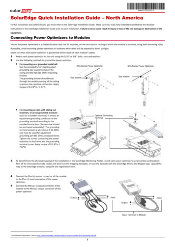
Step 1: Mounting the Power OptimizersllllllllThe steps in this chapter refer to module add-on power optimizers. For smart modules, start fromStep 3: Connecting Power Optimizers in Strings on the facing page. Also refer to the documentationsupplied with the smart modules.The power optimizer can be placed in any orientation.To allow for heat dissipation, maintain a 24.5 mm / 1" clearance distance between the poweroptimizer and other surfaces.If connecting more modules than optimizer inputs in parallel, use a branch cable (available fromSolarEdge).Position the power optimizer close enough to its module so that their cables can be connected.Make sure to use optimizers that have the required output cable length. You cannot use extensioncables between every two optimizers in a string; They may be used only to connect between rows/arrays or between the string and the inverter.The minimum and maximum string length guidelines are stated in the power optimizer datasheets.Refer to the SolarEdge Site Designer for string length verification. The SolarEdge Site Designer isavailable on the SolarEdge website at under Software Tools.Completely shaded modules may cause their power optimizers to temporarily shut down. This willnot affect the performance of the other power optimizers in the string, as long as the minimumnumber of unshaded power optimizers connected in a string of modules is met. If under typicalconditions fewer than the minimum optimizers are connected to unshaded modules, add moreoptimizers to the string.NOTEThe images contained in the following sections are for illustrative purposes only and may varydepending on product models.Step 1: Mounting the Power OptimizersFor each of the power optimizers1:1. Determine the power optimizer mounting location and use the power optimizer mounting bracketsto attach the power optimizer to the support structure . For frame-mounted power optimizersfollow the instructions supplied with the optimizers.2. If required, mark the mounting hole locations and drill the hole.CAUTION!Do not drill through the power optimizer or through the mounting holes. The drilling vibrations candamage the power optimizer and will void the warranty.3. Attach each power optimizer to the rack using the M6 (1/4'') stainless steel bolts, nuts and washers.Apply torque of 9.5 N*m / 7 lb*ft.4. Verify that each power optimizer is securely attached to the supporting structure or the module.NOTERecord power optimizer serial numbers and locations, as described i
Step 4: Reporting and Monitoring Installation Data 28 The SolarEdge Monitoring System 28 Providing Installation Information 29 Site Mapper Application 29 Creating a Site in the SolarEdge Monitoring Platform 29 Paper Template 29
