Transcription
DisclaimersDisclaimersImportant NoticeCopyright SolarEdge Inc. All rights reserved.No part of this document may be reproduced, stored in a retrieval system or transmitted, in any form orby any means, electronic, mechanical, photographic, magnetic or otherwise, without the prior writtenpermission of SolarEdge Inc.The material furnished in this document is believed to be accurate and reliable. However, SolarEdgeassumes no responsibility for the use of this material. SolarEdge reserves the right to make changes to thematerial at any time and without notice. You may refer to the SolarEdge web site (www.solaredge.com)for the most updated version.All company and brand products and service names are trademarks or registered trademarks of theirrespective holders.Patent marking notice: see http://www.solaredge.com/groups/patentThe general terms and conditions of delivery of SolarEdge shall apply.The content of these documents is continually reviewed and amended, where necessary. However,discrepancies cannot be excluded. No guarantee is made for the completeness of these documents.The images contained in this document are for illustrative purposes only and may vary depending onproduct models.Emission ComplianceThis equipment has been tested and found to comply with the limits applied by the local regulations.These limits are designed to provide reasonable protection against harmful interference in a residentialinstallation. This equipment generates, uses and can radiate radio frequency energy and, if not installedand used in accordance with the instructions, may cause harmful interference to radio communications.However, there is no guarantee that interference will not occur in a particular installation. If thisequipment does cause harmful interference to radio or television reception, which can be determined byturning the equipment off and on, you are encouraged to try to correct the interference by one or moreof the following measures:lReorient or relocate the receiving antenna.lIncrease the separation between the equipment and the receiver.lConnect the equipment into an outlet on a circuit different from that to which the receiver isconnected.lConsult the dealer or an experienced radio/TV technician for help.Changes or modifications not expressly approved by the party responsible for compliance may void theuser’s authority to operate the equipment.SolarEdge-StorEdge -Single Battery/High Capacity Installation MAN-01-00283-1.11
ContentsContentsDisclaimersImportant NoticeEmission ComplianceContentsHANDLING AND SAFETY INSTRUCTIONSSafety InformationIMPORTANT INVERTER SAFETY INSTRUCTIONSChapter 1: OverviewThe StorEdge Solution ComponentsAbout this GuideInstallation WorkflowChapter 2: Installing the Power OptimizersSafetyInstallation GuidelinesStep 1: Mounting the Power OptimizersStep 2: Connecting a PV Module to a Power OptimizerStep 3: Connecting Power Optimizers in StringsStep 4: Verifying Proper Power Optimizer ConnectionChapter 3: Installing the InverterInverter Package ContentsIdentifying the InverterInverter InterfacesInternal AC Breaker and Bypass SwitchMounting the InverterChapter 4: Installing the Backed-up Loads Panel and MeterInstalling the Backed-up Loads PanelElectricity Meter InstallationChapter 5: StorEdge Inverter ConnectionsOpening the StorEdge Connection Unit CoversInstalling the 9V BatteryConnecting the Strings to the InverterConnecting to the BatteryDIP Switch SetupBattery GroundingConnecting Communication to the MeterConnecting to the AC Grid and to Backed-up LoadsChapter 6: Commissioning the InstallationRemoving the Inverter CoverStep 1: Activating the SystemStep 2: Pairing Power Optimizers to the InverterStep 3: Verifying Proper OperationStep 4: Reporting and Monitoring Installation DataThe SolarEdge Monitoring 324252626262830313334343537393939SolarEdge StorEdge -Single Battery/High Capacity Installation MAN-01-00283-1.1
ContentsProviding Installation InformationSite Mapper ApplicationCreating a Site in the SolarEdge Monitoring PortalPaper TemplateChapter 7: User InterfaceLCD User ButtonsInverter Configuration – Setup ModeConfiguring the Inverter Using the LCD User ButtonsConfiguring the Inverter Using the LCD Light ButtonConfiguration Menu OptionsCountry and GridLanguageCommunicationPower ControlDisplayMaintenanceInformationStatus Screens - Operational ModeInitial StatusMain Inverter StatusEnergy Meter StatusTelemetry StatusID StatusServer Communication StatusIP StatusZigBee StatusWi-Fi StatusGSM StatusCommunication Ports StatusSmart Energy Management StatusPower Control StatusBattery StatusCharge/ Discharge Profile ProgrammingStatusChapter 8: Setting Up Communication to the Monitoring PortalCommunication TypesCommunication ConnectorsCreating an Ethernet (LAN) ConnectionCreating an RS485 Bus ConnectionVerifying the ConnectionChapter 9: System ConfigurationConfiguring the RS485 Bus for Battery and Meter ConnectionConfiguring StorEdge ApplicationBackup Power ApplicationsSystem Basic ConfigurationVerifying StorEdge Components FunctionalitySolarEdge-StorEdge -Single Battery/High Capacity Installation 7070733
ContentsAppendix A: Additional Battery ConnectionsAppendix B: TroubleshootingCommunication TroubleshootingDevice type, number and protocol are displayed incorrectlyTroubleshooting Ethernet CommunicationMeter Troubleshooting OK is not displayedAn error message is displayedPower [Wh] Import value is not advancingBattery TroubleshootingPower Optimizer TroubleshootingAdditional StorEdge TroubleshootingStorEdge Connection Unit LEDsError CodesGeneral Inverter Error CodesStorEdge-related Errors CodesSystem WarningsAppendix C: Replacing and Adding System ComponentsReplacing an Inverter9V Battery ReplacementFuse ReplacementStorEdge Connection Unit ReplacementRemoving the Existing StorEdge Connection UnitInstalling a New StorEdge Connection UnitAppendix D: Inverter 100100100101102StorEdge Inverter for Single Battery or High Capacity Technical Specifications4SolarEdge StorEdge -Single Battery/High Capacity Installation MAN-01-00283-1.1
HANDLING AND SAFETY INSTRUCTIONSHANDLING AND SAFETY INSTRUCTIONSDuring installation, testing and inspection, adherence to all the handling and safety instructions ismandatory. Failure to do so may result in injury or loss of life and damage to the equipment.Safety InformationThe following safety symbols are used in this document. Familiarize yourself with the symbols and theirmeaning before installing or operating the system.WARNING!Denotes a hazard. It calls attention to a procedure that, if not correctly performed or adhered to, couldresult in injury or loss of life. Do not proceed beyond a warning note until the indicated conditionsare fully understood and met.CAUTION!Denotes a hazard. It calls attention to a procedure that, if not correctly performed or adhered to, couldresult in damage or destruction of the product. Do not proceed beyond a caution sign until theindicated conditions are fully understood and met.NOTEDenotes additional information about the current subject.IMPORTANT SAFETY FEATUREDenotes information about safety issues.Disposal requirements under the Waste Electrical and Electronic Equipment (WEEE) regulations:NOTEDiscard this product according to local regulations or send it back to SolarEdge.SolarEdge-StorEdge -Single Battery/High Capacity Installation MAN-01-00283-1.15
IMPORTANT INVERTER SAFETY INSTRUCTIONSIMPORTANT INVERTERSAFETY INSTRUCTIONSSAVE THESE INSTRUCTIONSWARNING!The inverter cover must be opened only after shutting off the inverter ON/OFF switch located at thebottom of the inverter. This disables the DC voltage inside the inverter. Wait five minutes beforeopening the cover. Otherwise, there is a risk of electric shock from energy stored in the capacitors.WARNINGBefore operating the inverter, ensure that the inverter AC power cable and wall outlet are groundedproperly.WARNINGOpening the inverter and repairing or testing under power must be performed only by qualified servicepersonnel familiar with this inverter.WARNING!Do not touch the PV panels or any rail system connected when the inverter switch is ON, unlessgrounded.WARNING!Under single fault conditions, the Safe DC voltage is only guaranteed when using modules of upto 95Voc.CAUTION!This unit must be operated under the specified operating specifications, as described in the latesttechnical specification datasheet provided with the unit .NOTEThe StorEdge Connection Unit is NEMA type 3R rated . Unused glands should be sealed withappropriate seals.CAUTION!HEAVY OBJECT. To avoid muscle strain or back injury, use proper lifting techniques, and if required - alifting aid when removing or replacing.NOTEUse PV modules rated according to IEC 61730 class A.NOTEThe symbolappears at grounding points on the SolarEdge equipment. This symbol is also used inthis manual.6SolarEdge StorEdge -Single Battery/High Capacity Installation MAN-01-00283-1.1
IMPORTANT INVERTER SAFETY INSTRUCTIONSNOTEThe following warning symbols appear on the inverter warning label:Risk of electric shockRisk of electric shock from energy stored in the capacitor. Do not remove cover until 5minutes after disconnecting all sources of supply.Hot surface – To reduce the risk of burns, do not touch.WARNING!Shutting off the AC breaker does not disable the DC voltage inside the inverter. To obtain safe DCvoltage, turn off the inverter ON/OFF switch and the StorEdge Connection Unit ON/OFF switch.WARNING!Before operating the system, ensure that the inverter has been grounded properly.WARNING!When handling the battery, adhere to all manufacturer safety instructions.CAUTION!This unit must be operated under the specified operating conditions as described in the technicalspecifications supplied with the unit.NOTEThe battery used must be NRTL certified.NOTEFor battery decommissioning and disposal, follow the manufacturer requirements and instructions.SolarEdge-StorEdge -Single Battery/High Capacity Installation MAN-01-00283-1.17
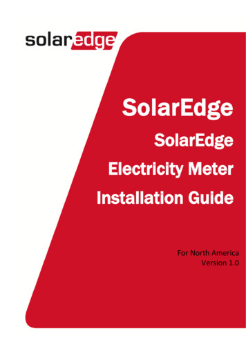
Chapter 1: OverviewChapter 1: OverviewStorEdge is SolarEdge's all-in-one solution that uses a single on-grid DC optimized inverter to manageand monitor both solar power generation and energy storage. Homeowners are automatically providedwith backup power in the event of grid interruption to power pre-selected loads. Solar energy can bestored in a battery for Smart Energy Management applications such as export control, offering demandresponse and peak shaving, and performing time of use shifting for reduced electric bills.The StorEdge Solution ComponentslllThe StorEdge Inverter for Single Battery or High Capacity with StorEdgeConnection Unit - The inverter manages battery and system energy, in addition to itstraditional functionality as a DC-optimized PV inverter. SolarEdge offers a StorEdgeinverter for High Power; For details, refer to its datasheet, athttp://www.solaredge.com/sites/default/files/se storedge high power inverterdatasheet eng.pdf.The StorEdge Connection Unit, located at the bottom of the inverter, allows simple installation andconnectivity to other system components and includes a DC Safety Switch.The SolarEdge Electricity Meter - The meter is used by the inverter for export/ consumptionreadings, and for Smart Energy Management applications, such as: export limitation, time-of-useprofile programming and maximizing self-consumption.The meter is required only in systems using Smart Energy Management applications (it is not requiredfor StorEdge systems used only for backup power).The Battery - A DC coupled battery designed to work with the SolarEdge system.Figure 1: StorEdge system componentsNOTEll8Additional SolarEdge inverters (without batteries) can be connected with RS485. The inverters willparticipate in export limitation and maximizing self-consumption.Connecting multiple inverters with RS485 master-slave connection requires an RS485 ExpansionKit (available from SolarEdge).PV modules connected to power optimizers are not mandatory for charge/discharge profileprogramming and for backup power.SolarEdge StorEdge -Single Battery/High Capacity Installation MAN-01-00283-1.1
Chapter 1: OverviewAbout this GuideThis document describes basic system connection and configuration - PV system (poweroptimizer strings), one inverter, one battery, backed-up loads panel and one meter.For additional configuration options refer to the StorEdge Solution Applications Connection and Configuration Guide, available redge backup applicationsconnection and configuration guide.pdf.SolarEdge-StorEdge -Single Battery/High Capacity Installation MAN-01-00283-1.19
Installation WorkflowInstallation WorkflowWhen installing the StorEdge system, follow this workflow to ensure all the components are connectedand functioning correctly.Step 1 - PV system installation - modules, power optimizers and inverter:lPower optimizers - as described in Installing the Power Optimizers on page 11.lInverter - as described in Installing the Inverter on page 16.Step 2 - Backed-up loads panel installation (required for Backup Power only): Refer to Connecting tothe AC Grid and to Backed-up Loads on page 33.Step 3 - Electricity Meter installation (required for Smart Energy Management only). Refer toElectricity Meter Installation on page 23.Step 4 - Connecting PV strings (DC) to the inverter - Refer to Connecting the Strings to the Inverter onpage 26.Step 5 - Connecting the battery to the inverter and mounting the battery. Refer to the installationinformation in the manufacturer documentation, and to StorEdge Inverter Connections on page 24.Step 6 - Connecting AC and backed-up loads to the inverter - connect the loads (AC), and meter. Referto StorEdge Inverter Connections on page 24.Step 7 - Commissioning the inverter - Activate the system and pair the power optimizers. Refer toCommissioning the Installation on page 34.Step 8 - Connecting to the monitoring portal. Refer to Setting Up Communication to the Monitoring Portalon page 59.Step 9 - System Configuration - Configuring the RS485 bus and StorEdge applications. Refer to SystemConfiguration on page 67.The following flowchart appears throughout this Installation Guide to assist with the installation steps:10SolarEdge StorEdge -Single Battery/High Capacity Installation MAN-01-00283-1.1
Chapter 2: Installing the Power OptimizersChapter 2: Installing the Power OptimizersSafetyThe following notes and warnings apply when installing the SolarEdge power optimizers. Some of thefollowing may not be applicable to smart modules:WARNING!When modifying an existing installation, turn OFF the inverter ON/OFF switch and the AC circuitbreaker on the main AC distribution panel.WARNING!Input and output connectors are not watertight until mated. Open connectors should be mated to eachother or plugged with appropriate watertight caps.CAUTION!Power optimizers are IP65/NEMA4 rated. Choose a mounting location where optimizers will not besubmerged in water.CAUTION!This unit must be operated according to the operating specifications provided with the unit.CAUTION!Cutting the power optimizer input or output cable connector is prohibited and will void the warranty.CAUTION!All PV modules must be connected to a power optimizer.SolarEdge-StorEdge -Single Battery/High Capacity Installation MAN-01-00283-1.111
Installation GuidelinesCAUTION!If you intend to mount the optimizers directly to the module or module frame, first consult the modulemanufacturer for guidance regarding the mounting location and the impact, if any, on module warranty.Drilling holes in the module frame should be done according to the module manufacturer instructions.CAUTION!Installing a SolarEdge system without ensuring compatibility of the module connectors with theoptimizer connectors may be unsafe and could cause functionality problems such as ground faults,resulting in inverter shut down. In order to ensure mechanical compatibility of the SolarEdge optimizersand the modules to which they are connected, use identical connectors from the same manufacturerand of the same type on both the power optimizers and on the modules.IMPORTANT SAFETY FEATUREModules with SolarEdge power optimizers are safe. They carry only a low safety voltage before theinverter is turned ON. As long as the power optimizers are not connected to the inverter or the inverter isturned OFF, each power optimizer will output a safe voltage of 1V.Installation GuidelinesllllllllllThe steps in this chapter refer to module add-on power optimizers. For smart modules, start fromStep 3: Connecting Power Optimizers in Strings on page 14. Also refer to the documentation suppliedwith the smart modules.The minimum and maximum string length guidelines are stated in the power optimizer datasheets.If connecting more modules than optimizer inputs in parallel , use a branch cable (available fromSolarEdge).Make sure to use optimizers that have the required output cable length. You can use extension cablesbetween rows and from the end of string to the inverter. Extension cables cannot be used betweentwo power optimizers within a string.The power optimizer can be placed in any orientation.Position the power optimizer close enough to its module so that their cables can be connected.To allow for heat dissipation, maintain a 2.5 cm/ 1" clearance distance between the power optimizerand other surfaces.Refer to the SolarEdge Site Designer for string length verification. The SolarEdge Site Designer isavailable on the SolarEdge website at under Software Tools.Completely shaded modules may cause their power optimizers to temporarily shut down. This willnot affect the performance of the other power optimizers in the string, as long as the minimumnumber of unshaded power optimizers connected in a string of modules is met. If under typicalconditions fewer than the minimum optimizers are connected to unshaded modules, add moreoptimizers to the string.Do not leave the power optimizers connectors disconnected. Open connectors should be mated toeach other.NOTEThe images contained in the following sections are for illustrative purposes only and may varydepending on product models.12SolarEdge StorEdge -Single Battery/High Capacity Installation MAN-01-00283-1.1
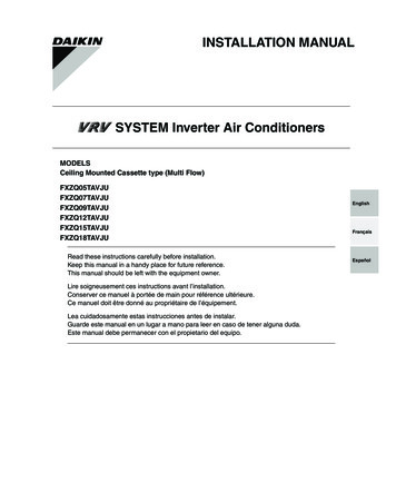
Chapter 2: Installing the Power OptimizersStep 1: Mounting the Power OptimizersFor each of the power optimizers1:1. Determine the power optimizer mounting location and use the power optimizer mounting bracketsto attach the power optimizer to the support structure . For frame-mounted power optimizersfollow the instructions supplied with the optimizers.2. If required, mark the mounting hole locations and drill the hole.CAUTION!Do not drill through the power optimizer or through the mounting holes. The drilling vibrations candamage the power optimizer and will void the warranty.3. Attach each power optimizer to the rack using the M6 (1/4'') stainless steel bolts, nuts and washers.Apply torque of 9.5 N*m / 7 lb*ft.4. Verify that each power optimizer is securely attached to the supporting structure or the module.NOTERecord power optimizer serial numbers and locations, as described in Providing InstallationInformation on page 40.Step 2: Connecting a PV Module to a PowerOptimizerNOTEImages are for illustration purposes only. Refer to the label on the product to identify the plus andminus input and output connectors.For each of the power optimizers1:llConnect the Plus ( ) output connector of the module to the Plus ( ) input connector of the poweroptimizer.Connect the Minus (-) output connector of the module to the Minus (-) input connector of thepower optimizer.Figure 2: Power optimizer connectors1Not applicable to smart modules.SolarEdg
SolarEdge StorEdge -Single Battery/High Capacity Installation MAN-01-00283-1.1 2 Contents. Providing Installation Information 40 Site Mapper Application 40 Creating a Site in the SolarEdge Monitoring Portal 41 Paper Template 41 . installation