Transcription
Installation GuideModbus TCP CardVLT Soft Starter MCD 600vlt-drives.danfoss.com
Modbus TCP CardInstallation GuideContentsContents1 Safety51.1Disclaimer51.2Warnings52 Introduction62.1Product Design62.2Compatibility62.3Network Connection63 Installation73.1Installing the Expansion Card73.2Network Connections73.2.1Ethernet Ports73.2.2Cables73.2.3EMC Precautions73.3Network Establishment73.4Addressing74 Device Configuration84.1Before Configuring the Device84.2Configuration Methods84.3Parameters for Configuring Network Settings84.4Enabling Network Control84.5On-board Web Server94.5.1Connect to the Device94.5.2Manage Users and Passwords104.5.2.1Adding a User104.5.2.2Deleting a User104.64.5.3Configuring the IP Address114.5.4Configure IoT Settings114.5.4.1Configuring MQTT Settings124.5.4.2Configuring OPC UA Settings13Scanning the Network134.6.113Identifying the Device with Ethernet Device Configuration Tool5 PLC Configuration5.1Configuration Requirements for PLCDanfoss A/S 2020.121515AN353424224484en-000101/130R0946 3
Modbus TCP CardInstallation Guide6 OperationContents166.1Requirements for Successful Operation166.2Device Classification166.3Ensuring Safe and Successful Control166.4Feedback LEDs167 Modbus Registers177.1Important Information177.2Command and Configuration Registers (Read/Write)177.3Parameter Management177.3.1Writing Parameters to the Soft Starter187.4Status Reporting Registers (Read Only)187.5Legacy Mode207.5.1Initializing Legacy Mode207.5.2Registers207.6Trip Codes8 Network Design24268.1Star Topology268.2Line Topology268.3Ring Topology278.4Combined Topologies279 twork299.4Power299.5Certification294 Danfoss A/S 2020.12AN353424224484en-000101/130R0946
Modbus TCP CardInstallation GuideSafety1 Safety1.1 DisclaimerThe examples and diagrams in this manual are included solely for illustrative purposes. The information contained in this manual issubject to change at any time and without prior notice. Responsibility or liability is never accepted for direct, indirect, or consequential damage resulting from the use or application of this equipment.1.2 WarningsW A R N I N GSHOCK HAZARDAttaching or removing accessories while the soft starter is connected to mains voltage may cause personal injury.-Before attaching or removing accessories, isolate the soft starter from mains voltage.W A R N I N GRISK OF PERSONAL INJURY AND EQUIPMENT DAMAGEInserting foreign objects or touching the inside of the soft starter while the expansion port cover is open may endanger personnel and can damage the soft starter.-Do not insert foreign objects in the soft starter with the port cover open.Do not touch the inside of the soft starter with the port cover open.Danfoss A/S 2020.12AN353424224484en-000101 / 130R0946 5
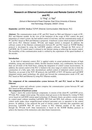
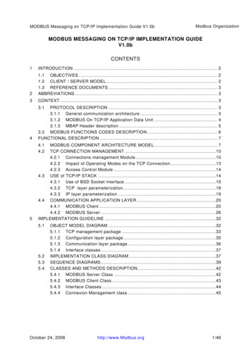
Modbus TCP CardInstallation GuideIntroduction2 Introduction2.1 Product DesignThe Modbus TCP Card allows the soft starter to connect to an Ethernet network and be controlled or monitored using an Ethernetcommunication model.Familiarity with Ethernet protocols and networks is required to operate the device successfully. For difficulties arising from usingthis device with 3rd-party products, including PLCs, scanners, and commissioning tools, contact the relevant supplier.2.2 CompatibilityThis communication expansion card is suitable for use with VLT Soft Starter MCD 600.This Installation Guide is intended for use with version 2.x of the VLT Soft Starter MCD 600 Modbus TCP Card. Version 1.x of theModbus TCP Card does not support custom users, TCP connection, or IoT operation.2.3 Network ConnectionTable 1: Supported ProtocolsModbus TCPIndustrial Ethernet via Modbus TCPTCPTransmission control protocol to connect to port 4000 of a PCMQTTMessage queue telemetry transportOPC UAOpen platform communications unified itResetLOCALMenuStore5 VLTSoft Starter1/L12/T14/T23/L25/L36/T3Illustration 1: Overview of Network Connections1Soft starter2Network switch3IoT connection (MQTT/OPC UA)6 Danfoss A/S 2020.124Industrial Ethernet connection to programmablelogic controller5TCP connection to VLT Motion Control Tool MCT10. Refer to the VLT Motion Control Tool MCT 10Operating Guide for connection details.AN353424224484en-000101 / 130R0946
Modbus TCP CardInstallation GuideInstallation3 Installation12e77ha739.103.1 Installing the Expansion CardProcedure1.2.Push a small flat-bladed screwdriver into the slot in the center of the expansion port cover and ease the cover away fromthe soft starter.Align the card with the expansion port. Gently push the card along the guide rails until it clicks into the soft starter.3.2 Network Connections3.2.1 Ethernet PortsThe device has 2 Ethernet ports. If only 1 connection is required, either port can be used.3.2.2 CablesWhen connecting to the device, make sure that the cables are of 1 of the following categories: Category 5 Category 5e Category 6 Category 6e3.2.3 EMC PrecautionsTo minimize electromagnetic interference, Ethernet cables should be separated from motor and mains cables by 200 mm (7.9 in).If the Ethernet cable must cross motor or mains cables, the crossing should be at an angle of 90 .3.3 Network EstablishmentThe controller must establish communications directly with each device before the device can participate in the network.3.4 AddressingEach device in a network is addressed using a MAC address and an IP address. The device can be assigned a static IP address during configuration or can be configured to accept a dynamic IP address (viaDHCP). The MAC address is fixed within the device and is printed on a label on the front of the device.Danfoss A/S 2020.12AN353424224484en-000101 / 130R0946 7
Modbus TCP CardInstallation GuideDevice Configuration4 Device Configuration4.1 Before Configuring the DeviceN O T I C EThe error LED flashes whenever the device is receiving power but is not connected to a network. The error LED will flash occasionally during the configuration process.N O T I C EAt power-up, the communication card loads the IP address stored in the soft starter.4.2 Configuration MethodsNetwork communication parameters for the communication card can be set via the soft starter or via the on-board web server. The card uses a static IP address by default. To enable DHCP addressing, set parameter 12–20 DHCP to enable or change thesetting via the on-board web server. The IP address can be set via the programmable parameters of the soft starter. The web server can configure the IP address and messaging settings for MQTT/OPC UA operation.4.3 Parameters for Configuring Network SettingsUse parameters 12-8 to 12-21 to configure the network address. The parameters can be set via the Main Menu, via the Setup Tools,or by uploading a configuration file via USB Save & Load.ParameterDefault12-8 Gateway Address19212-9 Gateway Address 216812-10 Gateway Address 3012-11 Gateway Address 410012-12 IP Address19212-13 IP Address 216812-14 IP Address 3012-15 IP Address 4212-16 Subnet Mask25512-17 Subnet Mask 225512-18 Subnet Mask 325512-19 Subnet Mask 4012-20 DHCPDisable12-21 Location ID04.4 Enabling Network ControlN O T I C EIf the reset input is active, the soft starter does not operate. If a reset switch is not required, use parameter 7-9 to set the resetinput to normally open or fit a link across terminals RESET, COM on the soft starter.8 Danfoss A/S 2020.12AN353424224484en-000101 / 130R0946
Modbus TCP CardInstallation GuideDevice ConfigurationProcedure1.Set parameter 1-1 Command Source to Network for the soft starter to accept commands from the Modbus TCP Card.4.5 On-board Web Server4.5.1 Connect to the Devicee77ha807.10To configure settings using the on-board web server, the Modbus TCP Card must be installed in a soft starter, control power mustbe available, and the card and computer must both be connected to the Ethernet network.The computer must use a fixed IP address (not DHCP) and the same subnet mask as the card. The default IP address for the card is192.168.0.2. The default subnet mask is 255.255.255.0.e77ha814.10Once connected, the web server reports basic information about the card and the soft starter.Modbus TCPModbus TCPMCD 600Danfoss A/S 2020.12AN353424224484en-000101 / 130R0946 9
Modbus TCP CardInstallation GuideDevice Configuration4.5.2 Manage Users and PasswordsN O T I C EFor security reasons, define a custom administrator ID and password. The default username and password are:-Username: danfoss adminPassword: danfoss adminN O T I C EVersion 1.x of the Modbus TCP Card does not support custom users.The Modbus TCP Card supports multiple users and levels of privilege. Users can view the home screen and IP settings. Supervisors can view the home screen and IP settings, and they can change configuration settings. Administrators can view the home screen, change configuration settings, and add or delete users.e77ha808.104.5.2.1 Adding a User152634Procedure1.Connect to the web server and click Administration.2.Click Create new user.Enter the new username and password.3.4.5.6.Click Create an account.Set privileges (user, supervisor, administrator) as appropriate.Click Save changes.4.5.2.2 Deleting a UserProcedure1.Connect to the web server and click Administration.2.Select the required entry in the user list and click Delete.3.Click Delete again to confirm the action.10 Danfoss A/S 2020.12AN353424224484en-000101 / 130R0946
Modbus TCP CardInstallation GuideDevice Configuration4.5.3 Configuring the IP AddressN O T I C Ee77ha806.10For version 1.x of the Modbus TCP Card, changes made via the web server are not stored in the soft starter and will be lost whencontrol power is cycled.123Procedure1.2.3.Connect to the web server and click IP Setting.Edit settings as required. To enable DHCP addressing, tick the DHCP checkbox.Click Submit to send the new settings to the device.4.5.4 Configure IoT SettingsThe Modbus TCP Card supports soft starter status monitoring via IoT. The card cannot control or program the soft starter.N O T I C EVersion 1.x of the Modbus TCP Card does not support IoT operation.Danfoss A/S 2020.12AN353424224484en-000101 / 130R0946 11
Modbus TCP CardInstallation GuideDevice Configuratione77ha810.104.5.4.1 Configuring MQTT SettingsProcedure1.Connect to the web server and click Configuration.2.Select MQTT Client.3.Tick the Enable checkbox to enable MQTT client operation.The MQTT client is enabled by default.4.Click Connection and configure the settings as required.5.Click Connections Actions to select which information the card should publish.6.Click Submit to save all settings in the card.12 Danfoss A/S 2020.12AN353424224484en-000101 / 130R0946
Modbus TCP CardInstallation GuideDevice Configuratione77ha813.104.5.4.2 Configuring OPC UA SettingsProcedure1.Connect to the web server and click Configuration.2.Select OPC UA Server.3.Tick the Enable checkbox to enable OPC UA client operation.The OPC UA client is enabled by default.4.Click Server Configuration and configure the settings as required.5.Select Actions to select the actions for different object instances.6.Click Submit to save all settings in the card.4.6 Scanning the NetworkIf there is no connection to the web server and the soft starter cannot be accessed physically, use the Ethernet Device ConfigurationTool to scan the network and identify the device. Changes made via the Ethernet Device Configuration Tool cannot be stored permanently in the device and will be lost when the control power is cycled.Download the Ethernet Device Configuration Tool from www.danfoss.com under the sections Services/PC-tools.N O T I C EIf the PC has a firewall enabled, add the tool to the list of authorized programs.4.6.1 Identifying the Device with Ethernet Device Configuration ToolProcedure1.2.Start the Ethernet Device Configuration Tool.Click Search Devices.Danfoss A/S 2020.12AN353424224484en-000101 / 130R0946 13
Modbus TCP CardDevice Configuratione77ha641.10Installation Guide 3.The software searches for connected devices.Use the IP address to connect to the device via the web server.14 Danfoss A/S 2020.12AN353424224484en-000101 / 130R0946
Modbus TCP CardInstallation GuidePLC Configuration5 PLC Configuration5.1 Configuration Requirements for PLCe77ha632.10The PLC must be configured to map registers within the communication card to addresses within the PLC.The device must be configured directly in the PLC. No extra files are required.Danfoss A/S 2020.12AN353424224484en-000101 / 130R0946 15
Modbus TCP CardInstallation GuideOperation6 Operation6.1 Requirements for Successful OperationThe Modbus TCP Card must be controlled by a Modbus client (such as a PLC), which complies with the Modbus Protocol Specification. For successful operation, the client must also support all functions and interfaces described in this manual.N O T I C EThe available features and parameter details may vary according to the model and software version of the soft starter. Refer tothe VLT Soft Starter MCD 600 Operating Guide for details of parameters and supported features.6.2 Device ClassificationThe Modbus TCP Card is a Modbus server and must be managed by a Modbus client over Ethernet.6.3 Ensuring Safe and Successful ControlData written to the device remains in its registers until the data is overwritten or the device is reinitialized. If the soft starter is controlled via parameter 7-1 Command Override or is disabled via the reset input (terminals RESET, COM ), fieldbus commands shouldbe cleared from the registers. If a command is not cleared, it is re-sent to the soft starter once fieldbus control resumes.Port 1Port 2TX/RX2TX/RX1LINK 2LINKSTATUS1KeypadERRORe77ha742.106.4 Feedback LEDsTable 2: LED DescriptionsLED nameLED stateDescriptionErrorOffNo error.FlashingSystem error.OnCommunication error.OffThe device is not powered up.Slow flashThe device is ready but not configured.Fast flashCommunication has been established.OffNo network connection.OnConnected to a network.FlashingTransmitting or receiving data.OffNo network connection.StatusLink xTX/RX x16 Danfoss A/S 2020.12AN353424224484en-000101 / 130R0946
Modbus TCP CardInstallation GuideModbus Registers7 Modbus Registers7.1 Important InformationN O T I C EThe available features and parameter details may vary according to the model and software version of the soft starter. Refer tothe VLT Soft Starter MCD 600 Operating Guide for details of parameters and supported features.N O T I C EAll references to registers mean the registers within the communication card unless otherwise stated.7.2 Command and Configuration Registers (Read/Write)Table 3: Details of Command and Configuration d (single write)0–7To send a command to the soft starter, write the required value:00000000 Stop00000001 Start00000010 Reset00000100 Quick stop (coast to stop)00001000 Forced communication trip00010000 Start using Parameter Set 100100000 Start using Parameter Set 201000000 Reserved10000000 Reserved8–14Reserved15Must 10–15Manage soft starter programmable ed40009–40xxxParameter management (single/multiple read or multiple write)7.3 Parameter ManagementParameters can be read from and written to the soft starter. When writing parameters to the soft starter, every parameter is updatedto match the values in the PLC.N O T I C EWhile parameters are being written, the soft starter cannot start/stop the motor.The Modbus TCP protocol limits read/write operations to a maximum of 123 registers at one time. The registers must be consecutive.Danfoss A/S 2020.12AN353424224484en-000101 / 130R0946 17
Modbus TCP CardInstallation GuideModbus RegistersTo avoid loss of communications due to an unintentional change of network configuration, write the network address parametersettings before writing start/stop parameter settings.7.3.1 Writing Parameters to the Soft StarterN O T I C EFor reliable operation, the parameter block containing network configuration settings must be written first.Procedure1.2.3.Configure all soft starter parameter values in the PLC as required, including IP address, gateway address, subnet mask, andDHCP configuration.Write the parameter block that includes the network parameter settings from the PLC to the soft starter.Write the other parameter blocks from the PLC to the soft starter until all parameter values have been written.7.4 Status Reporting Registers (Read Only)N O T I C EFor models MCD6-0063B and smaller (soft starter model ID 1 4), the current reported via communications registers is 10 timesgreater than the actual value.Table 4: Description of Read served30600Product information30601Model number30602Reserved30603Reserved30604Starter state18 Danfoss A/S 2020.12BitsDetails0–5Binary protocol version6–8Parameter list major version9–15Product type code: 15 MCD 6000–7Reserved8–15Soft starter model ID0–40 Reserved1 Ready2 Starting3 Running4 Stopping5 Not ready (restart delay, restart temperature check, run simulation,reset input is open)6 Tripped7 Programming modeAN353424224484en-000101 / 130R0946
Modbus TCP CardInstallation GuideRegisterDescriptionModbus RegistersBitsDetails8 Jog forward9 Jog 13CurrentCurrentMotor temperaturePower% Power factorVoltageCurrentCurrentCurrentDanfoss A/S 2020.1251 Warning60 Uninitialized1 Initialized7Command source0 Remote LCP, Digital Input, Clock1 Network8Reserved90 Negative phase sequence1 Positive phase sequence10–15Reserved0–13Average rms current across all 3 phases14–15Reserved0–9Current (% motor FLC)10–15Reserved0–7Motor thermal model (%)8–15Reserved0–11Power12–13Power scale0 Multiply power by 10 to get W1 Multiply power by 100 to get W2 Power (kW)3 Multiply power by 10 to get kW14–15Reserved0–7100% power factor of 18–15Reserved0–13Average rms voltage across all 3 phases14–15Reserved0–13Phase 1 current (rms)14–15Reserved0–13Phase 2 current (rms)14–15Reserved0–13Phase 3 current (rms)14–15ReservedAN353424224484en-000101 / 130R0946 19
Modbus TCP CardInstallation GuideModbus e0–13Phase 1 voltage14–15Reserved0–13Phase 2 voltage14–15Reserved0–13Phase 3 voltage14–15Reserved0–7Parameter list minor revision8–15Parameter list major version306153061630617VoltageVoltageParameter list version number30618Digital input state0–15For all inputs, 0 open, 1 closed (shorted)0 Start/Stop1 Reserved2 Reset3 Input A4 Input B5–15 Reserved30619Trip code0–15See the chapter Trip Codes.8–15Reserved30620–30631ReservedN O T I C EThe reset input is normally closed by default. If parameter 7-9 Reset/Enable Logic is set to normally open, the reported state isinverted (0 closed, 1 open).7.5 Legacy ModeThe Modbus TCP Card can also operate in Legacy Mode, which uses the same registers as the clip-on Modbus RTU Module suppliedby Danfoss for use with older soft starters. Some registers differ from those specified in the Modbus protocol specification.7.5.1 Initializing Legacy ModeIf the card has been operating in Standard Mode, it must be reset before communicating in Legacy Mode. To initialize the card forLegacy Mode, either: cycle control power, or reset register 40001 to 0 (write 0 to bits 0–15).7.5.2 RegistersN O T I C EFor models MCD6-0063B and smaller, the current reported via communications registers is 10 times greater than the actual value.N O T I C ELegacy Mode reports read-only status information in registers 40003 onwards to match the register definitions of the clip-onModbus Module. Identical data is also available via registers 30003 onwards.20 Danfoss A/S 2020.12AN353424224484en-000101 / 130R0946
Modbus TCP CardInstallation GuideModbus RegistersTable 5: Description of Registers in Legacy ModeRegisterDescription40001Reserved40002Command (single write)40003Soft starter state40004Reserved40005Motor current40006Motor Parameter management (single or multiple read/ write)40600VersionDanfoss A/S 2020.12BitsDetails0–2To send a command to the starter, write the required value:1 Start2 Stop3 Reset4 Quick stop (coast to stop)5 Forced communication trip6 Start using Parameter Set 17 Start using Parameter Set 23–15Reserved0–31 Ready2 Starting3 Running4 Stopping (including braking)5 Restart delay (including temperature check)6 Tripped7 Programming mode8 Jog forward9 Jog reverse41 Positive phase sequence (only valid if bit 6 1)51 Current exceeds FLC60 Uninitialized1 Initialized7–15Reserved0–7Average 3-phase motor current (A)8–15Reserved0–7Motor thermal model (%)8–15Reserved0–7Manage soft starter programmable parameters. See the VLT SoftStarter MCD 600 Operating Guide for a complete parameter list.8–15Reserved0–5Binary protocol version6–8Parameter list version number9–15Product type code:AN353424224484en-000101 / 130R0946 21
Modbus TCP CardInstallation GuideRegisterDescriptionModbus RegistersBitsDetails15 MCD 60040601Model number40602Reserved40603Reserved40604Starter state40605406064060740608CurrentCurrentMotor temperaturePower22 Danfoss A/S 2020.120–7Reserved8–15Soft starter model ID0–40 Reserved1 Ready2 Starting3 Running4 Stopping5 Not ready (restart delay, restart temperature check, run simulation,reset input is open)6 Tripped7 Programming mode8 Jog forward9 Jog reverse51 Warning60 Uninitialized1 Initialized7Command source0 Remote LCP, Digital Input, Clock1 Network8Reserved90 Negative phase sequence1 Positive phase sequence10–15Reserved0–13Average rms current across all 3 phases14–15Reserved0–9Current (% motor FLC)10–15Reserved0–7Motor thermal model (%)8–15Reserved0–11Power12–13Power scale0 Multiply power by 10 to get W1 Multiply power by 100 to get W2 Power (kW)3 Multiply power by 10 to get kWAN353424224484en-000101 / 130R0946
Modbus TCP CardInstallation 61640617Description% Power ltageParameter list version numberModbus RegistersBitsDetails14–15Reserved0–7100% power factor of 18–15Reserved0–13Average rms voltage across all 3 phases14–15Reserved0–13Phase 1 current (rms)14–15Reserved0–13Phase 2 current (rms)14–15Reserved0–13Phase 3 current (rms)14–15Reserved0–13Phase 1 voltage14–15Reserved0–13Phase 2 voltage14–15Reserved0–13Phase 3 voltage14–15Reserved0–7Parameter list minor revision8–15Parameter list major version40618Digital input state0–15For all inputs, 0 open, 1 closed (shorted)0 Start/Stop1 Reserved2 Reset3 Input A4 Input B5–15 Reserved40619Trip code0–7See the chapter Trip Codes8–15Reserved40620–40631ReservedN O T I C EThe reset input is normally closed by default. If parameter 7-9 Reset/Enable Logic is set to normally open, the reported state isinverted (0 closed, 1 open).Danfoss A/S 2020.12AN353424224484en-000101 / 130R0946 23
Modbus TCP CardInstallation GuideModbus Registers7.6 Trip CodesCodeDescription255No trip1Excess start time2Motor overload3Motor thermistor4Current imbalance5Frequency6Phase sequence7Overcurrent8Power loss9Undercurrent10Heat sink overtemperature11Motor connection12Input A trip13FLC too high14Unsupported option (function not available in inside delta)15Communications card fault16Network r out of range20Motor overload24Input B trip26L1 phase loss27L2 phase loss28L3 phase loss29L1-T1 shorted30L2-T2 shorted31L3-T3 shorted33Time-overcurrent (bypass overload)34SCR overtemperature35Battery/clock36Thermistor circuit24 Danfoss A/S 2020.12AN353424224484en-000101 / 130R0946
Modbus TCP CardInstallation GuideCodeDescription47Overpower48Underpower56LCP disconnected57Zero speed detect58SCR Itsm59Instantaneous overcurrent60Rating capacity70Current Read Err L171Current Read Err L272Current Read Err L374Motor connection T175Motor connection T276Motor connection T377Firing fail P178Firing fail P279Firing fail P380VZC fail P181VZC fail P282VZC fail P383Low control volts84–96Internal fault x. Contact the local supplier with the fault code (x).Danfoss A/S 2020.12Modbus RegistersAN353424224484en-000101 / 130R0946 25
Modbus TCP CardInstallation GuideNetwork Design8 Network Design8.1 Star Topologye77ha628.10In a star network, all controllers and devices connect to a central network switch.Illustration 2: Example of Star Topology8.2 Line Topologye77ha629.10In a line network, the controller connects directly to 1 port of the 1st card. The 2nd Ethernet port connects to another card, which inturn connects to another device until all devices are connected.Illustration 3: Example of Line TopologyN O T I C EThe device has an integrated switch to allow data to pass through in line topology. The device must be receiving control powerfrom the soft starter for the switch to operate.N O T I C EIf the connection between 2 devices is interrupted, the controller cannot communicate with devices after the interruption point.26 Danfoss A/S 2020.12AN353424224484en-000101 / 130R0946
Modbus TCP CardInstallation GuideNetwork DesignN O T I C EEach connection adds a delay to the communication with the next device. The maximum number of devices in a line network is32. Exceeding this number may reduce the reliability of the network.8.3 Ring Topologye77ha630.10In a ring topology network, the controller connects to the 1st card via a network switch. The 2nd Ethernet port of the card connectsto another device, which in turn connects to another device until all devices are connected. The final device connects back to theswitch.The device supports beacon-based ring node configuration.Illustration 4: Example of Ring TopologyN O T I C EThe network switch must support loss of line detection.8.4 Combined TopologiesA single network can include both star and line components.Danfoss A/S 2020.12AN353424224484en-000101 / 130R0946 27
Modbus TCP CardInstallation Guidee77ha631.10Network DesignIllustration 5: Example of Combined Topologies28 Danfoss A/S 2020.12AN353424224484en-000101 / 130R0946
Modbus TCP CardInstallation GuideSpecifications9 Specifications9.1 ConnectionsSoft starter6-way pin assemblyContactsGold flashNetworkRJ459.2 SettingsIP addressAutomatically assigned, configurableDevice nameAutomatically assigned, configurable9.3 NetworkLink speed10 Mbps, 100 Mbps (auto-detect)Full duplexAuto crossover9.4 PowerConsumption (steady state, maximum)35 mA@24 V DCReverse polarity protectedGalvanically isolated9.5 CertificationRCMIEC 60947-4-2CEEN 60947-4-2Danfoss A/S 2020.12AN353424224484en-000101 / 130R0946 29
Danfoss A/SUlsnaes 1DK-6300 Graastenvlt-drives.danfoss.comDanfoss can accept no responsibility for possible errors in catalogs, brochures and other printed material. Danfoss reserves the right to alter its products without notice. Thisalso applies to products already on order provided that such alterations can be made without subsequential changes being necessary in specifications already agreed. Alltrademarks in this material are property of the respective companies. Danfoss and the Danfoss logotype are trademarks of Danfoss A/S. All rights reserved.*130R0946*Danfoss A/S 2020.12*M0025601*AN353424224484en-000101 / 130R0946
This Installation Guide is intended for use with version 2.x of the VLT Soft Starter MCD 600 Modbus TCP Card. Version 1.x of the Modbus TCP Card does not support custom users, TCP connection, or IoT operation. 2.3 Network Connection Table 1: Supported Protocols Protocols Modbus TCP Industrial Ethernet via Modbus TCP TCP Transmission control .