Transcription
ICSICSELECTRONICSa division of Systems West Inc.MODBUSMODEL 9009 and 9099Ethernet Modbus InterfacesInstruction Manual
MODEL 9009 and 9099Ethernet Modbus InterfacesInstruction Manual90999009ICSICSELECTRONICSdivision of Systems West Inc.7034 Commerce Circle, Pleasanton, CA 94588Phone 925.416.1000, Fax 925.416.0105Web Site http://www.icselect.comiPublication Number 120217July 2017 Edition Rev 2
LIMITED WARRANTYWithin 12 months of delivery, ICS Electronics will repair or replace this product, at ouroption, if any part is found to be defective in materials or workmanship (labor is included).Return this product to ICS Electronics, or other designated repair station, freight prepaid,for prompt repair or replacement. Contact ICS for a return material authorization (RMA)number prior to returning the product for repair.CERTIFICATIONICS Electronics certifies that this product was carefully inspected and tested at the factoryprior to shipment and was found to meet all requirements of the specification under whichit was furnished.EMI/RFI WARNINGThis equipment generates, uses, and can radiate radio frequency energy and, if not installedand used in accordance with the instruction manual, may cause interference to radio communications. The Model 9099 has been tested and found to comply with the limits for aClass A computing device pursuant to Subpart J of Part 15 of the FCC Rules and to complywith the EEC Standards EN 55022; VDE 0878-22:2011-12 and EN 55024:2010; VDE 087824:2010-09 which are designed to provide reasonable protection against such interferencewhen operated in a commercial environment. Operation of this equipment in a residentialarea is likely to cause interference, in which case the user, at his own expense, will be requiredto take whatever measures may be required to correct the interference.Certificate of Conformance reproduced in Figure 1-2.TRADEMARKSThe following trademarks referred to in this manual are the property of the followingcompanies:VEE is a trademark of Agilent, Palo Alto, CALabView is a Trademark of National istruments, Austin, TXICS and GPIB AnyWhere are trademarks of ICS Electronics, Pleasanton, CA 2013-2017 ICS Electronics div of Systems West Inc.ii
ContentsGeneral InformationProduct Description, Model Numbers, VXI-11 Conformance, InterfaceSpecifications, Web Server, Configurable Functions and Default Settings,Indicators, Physical Specifications, Certifications and Accessories.1InstallationShipment Verification, Installation Guide, Configuration Instructions,Serial Connections, 9009 Connections, Internal Jumper Settings andRack Mounting Instructions.2OperationOperation Description, Status Reporting Structure, IEEE-488.2and SCPI Conformance, SCPI Commands, Modbus Commands,Programming Guidelines, VXI-11 Keyboard, Error Logger Utilityand OEM Documentation.3Theory of OperationBlock Diagram Descriptions4Maintenance, Troubleshooting and RepairMaintenance, Troubleshooting Guide, Selftest Error Codes, Revertingto Factory Settings, Updating Firmware, Sanitizing Procedure, andRepair Information5AppendicesA1 IEEE-488.1, IEEE-488.2 and SCPI DescriptionsA2 VXI-11 ConceptA3 VXI-11 RPCgen InformationA4 ICS RPC Configuration CommandsA5 HTML VariablesIndexiAI
11General Information1.1INTRODUCTIONThis section provides a description and specifications for ICS's Model 9009and 9099 Ethernet to Modbus Interfaces. All specifications and functionaldescriptions apply to both units unless otherwise stated.1.2DESCRIPTIONThe Model 9009 and 9099 Ethernet to Modbus Interfaces provide a user withmultiple ways to control Modbus RTU slave devices with RS-232 and RS-422/RS-485 signals. The Model 9009 is a PC board assembly with an Ethernet,GPIB and USB user interfaces. The Model 9099 is an enclosed unit that hasan Ethernet user interface. Both units have a 9-pin connector with user selected RS-232 or RS-422/RS-485 signals for controlling Modbus RTU slavedevices.In both units, the Ethernet Interface provides a user with multiple protocolsand conversion capability to control serial Modbus RTU devices. The EthernetInterfaces support the VXI-11, raw-socket and Modbus TCP/IP conversion andinclude a webserver with HTML control pages for the more popular temperature controllers.The VXI-11 and raw-socket protocols let the user send simple commandswith ASCII values over a 10/100 Mbs TCP/IP network to control and queryModbus slave devices. The simple commands are converted into the ModbusRTU messages and the CRC checksum is added to make a complete ModbusRTU packet. The Modbus RTU packets are sent serially over a RS-232 linkto a single Modbus slave device or over a RS-485 network to one or multipleModbus devices. Responses are checked and valid response data from a queryis returned when the 9099 is next addressed to talk.1-1
1The 9099 contains a number of advanced features that increase its flexibilityand simplifies their use in test system applications. The 9099 is an IEEE-488.2compatible interface with an expanded Status Reporting Structure that complieswith the SCPI standard. SCPI commands are used to set the GPIB, USB andserial configuration, and to enable bits in the Status Reporting Structure togenerate Service Requests. The user can also enter his own IDN message topersonalize the unit as part of his assembly.Modbus TCP/IP packets are automatically converted into Modbus RTU packets.The Modbus conversion is transparent and the 9099 does not restrict the Modbusaddresses, functions or data but they are restricted by the capabilities of theslave device. Response data from the slave device is returned to the senderas a TCP/IP response packet. Message length is limited to 255 bytes.The 9099 contains a webserver which provides the user with several typesof webpages. The Welcome page displays information about the 9099 anddisplays its status. The Configuration Page provides a way to view the 9099'scurrent settings and to change the network, serial and USB settings. Thereis some overlap with the SCPI setup commands. A rear panel 'LAN Reset'button allows the user to return the 9099 to its default network settings. TwoTemperature Controller pages and a general Control page let a user view andcontrol different processes and devices run by temperature controllers.The 9009's GPIB and USB Interfaces access the 9009's parser as does theEthernet interface and use the same simple commands to control and queryModbus slave devices as does the Ethernet interface. The GPIB interface isfully IEEE-488.2 compliant. The USB Interface uses Microsoft's Virtual COMport driver for easy communication with the 9009.The 9009 and 9099 are VXI-11.3 compliant, can be used in systems with LXIdevices and can be found with the LXI 'VXI-11 Discovery Method'.The Model 9009 is a 5.5 x 5.5 inch PC board assembly that can be mounted onthe rear panel or inside a host chassis. It accepts 5 to 15 Vdc power.The Model 9099 is packaged in a small Minibox metal case that is less than1U in height (1.6 inches) The front panel contains the power switch and LEDswhich indicate the unit's status. The rear panel contains the Ethernet and serial connectors, LAN Reset button and a DC power jack. The 9099 acceptsa wide range of DC voltages and is shipped with an universal power adapterand plugs.1-2
1.3MODEL SPECIFICATIONSThe following specifications apply to all 9009 and 9099 models. Optionsfor your unit may be found by comparing the list below to those listed on theprogram label on your unit.90x9 - XGeneral Model NumberOption Codes-6-7-8-9-USpecial settingsSpecial ProgramHardware modificationFactory Rack MountedShip with Universal 115/230 Vac Adapter1-31
1.4.1VXI-11 CONFORMANCEThe 9099 complies with the VXI-11.3 Specification.1.4.1RPC ProtocolThe RPC protocol conforms to ONC RPC Version 2.1.4.2SocketsThe 9099's VXI-11 service supports 15 TCP/IP sockets for client communication with a maximum of 4 active sockets. The sockets are normally opened andclosed by the clients. The unit will close the socket and release all resourcesif a broken connection is detected or when the link count goes to zero if AutoDisconnect is enabled.There is a separate socket for UDP RPC Port Mapper communication.1.4.3ChannelsSupports Core, Abort and Interrupt channels. Core and Abort channels each usea socket connection. A reverse Interrupt channel is a TCP/IP socket connectionthat does not count against the 15 client communication sockets limit.1.4.4Device Links and LocksThe 9099 supports a maximum of 64 device links and 64 locks that can be usedover multiple Core channels by one or more clients.1.4.5VXI-11 Interface NameThe 9099 has only one instrument personality and the default name is inst0.The name may be changed to any 8 character string.1.4.6VXI-11.3 Supported FunctionsThe 9099 supports all VXI-11.3 functions including:create linkdevice lockdevice readdevice remotedevice intr SRQdestroy linkcreate intr channel destroy intr channeldevice unlockdevice abortdevice writedevice cleardevice triggerdevice localdevice readstbcreate intr channeldevice enable SRQ1-4
1.5ETHERNET INTERFACE1.5.1Type1IEEE-802.3 Compliant, Auto MDIX1.5.2SpeedAuto speed sensing, 10 Mbs with 10BaseT and 100 Mbs with 100BaseT1.5.3Network AddressStatic: IP Address, Subnet Mask, and Gateway IPv4 values are user set from0.0.0.0 to 255.255.255.255. Default values are listed in Table 1-3.DHCP: Unit accepts IPv4 address from a DHCP Server or falls back to anAutoIP of 169.254.90.99. The 9009 falls back to 169.254.90.09.1.5.4KeepAlive MessageUser enabled. Message sent if no activity for 120 minutes. Releases the socketand all associated resources if the connection is broken.1.5.5COMM TimeoutUser set period of 0 to 232 seconds. Releases socket and all associated resourcesif no activity occurred during the time period.1.5.6Port UsageTable 1-19099 Port UsagePortUsageProtocols23Raw socketTCP1115025555RPC Port MapperModbus TCP/IPCore Channelxxxx5556Reverse NotificationConfiguration Port,Error Logger802000-2999Internal WebServerAbort ChannelNotesConfigurable port#HTML over TCP Web BrowserRPC over TCPTCPRPC over TCPRPC over TCPRPC over TCPRPC1-5Defined by user
Table 1-21FACTORY NETWORK SETTINGSCommandFunctionChoicesDefaultIP Address ModeStatic or Dynamicwith autoIP fallbackto 169.254.90.99 or169.254.90.09.IP AddressSource (1)StaticE0.0.0.0 to255.255.255.255192.168.0.254ENet Mask0.0.0.0 to255.255.255.255255.255.255.0EGateway IP0.0.0.0 to255.255.255.255192.168.0.1E120 secEOnECOMM TimeoutIP KeepAliveOn or OffInterface NameAny string(4)inst0EAuto DisconnectSocketsOn or OffOffEUser Descriptionany stringblankERaw Socket Enable On or OffOffERaw Socket Port#0-6563523ERaw Socket EchoEnableOn or OffOffENotes:1. E Set via Ethernet Interface using a web browser.2. Function definitions are described in Table 2-13. The MAC Address is factory set and is not user changeable. The MAC Addresscan be read with the VXI-11 Configuration Utility or with a web browser.4. The interface name defines the device type. Changing it may cause your application to stop working.5. Setting Auto Disconnect on may cause your application to loose its connectionto the 9099 if the application destroys all links.1-6
1.5.7ProtocolsTCP/IPUPD and TCP/IPModbus TCP/IPRaw Socket1.5.8for VXI-11, HTTP and RPC communicationfor RPC Port Mapper commandsfor Modbus RTU conversionfor telnet compatible IP packet communicationRaw SocketThe 90x9's Raw Socket configuration is set to the following values:Port 23Sockets4Echo OffPromptNoneTimeout120 seconds fixedLogon messageMessage equal to *IDN? response.TerminatorLinefeed characterCarriage Returns Client generated carriage returns are ignored.BackspacePrior character deleted up to the start of the buffer.Echo On command Cntl-EEcho off command Cntl-FThe Raw Socket connection will be closed if there is no communication for 120seconds. To prevent the Raw Socket from timing out and disconnecting, theclient can issue a no change message like space-backspace or a Cntl-E-Cntl-Fsequence, on an occasional basis, to restart the timeout counter.If Echo was enabled, all client character will be echoed back to the client. Theecho sequence for a backspace is a BS-space-BS to visually wipe the deletedcharacter off of the telnet client screen.1-71
1.61INTERNAL WEB SERVERThe 9099's WebServer provides HTML web pages to W3C compliant browsers.1.6.1HTML PagesThe 9099's HTML pages conform to HTML version 4.01 or XHTML version1.0. The WebServer serves the stored pages after substituting values for thevariable placeholders. The variables are listed in Appendix 5. The standardpages 6.3404 Error Page (required page)501 Error Page (required page)Welcome Page (required page)Configuration PageConfirmation PageGeneral purpose 9099 and Modbus device control pageReboot PageSample F4 Control PageSample F4T Control PageSample EZ Zone Control PageGraphicsICS'S HTML upload utility supports files with .gif, .jpg, .png or .hgl extensions.The standard graphic is:ICS-Logo.gif ICS Logo1.6.4HTML User ConfigurabilityThe user can replace the HTML pages and image files with modified pages oradd additional pages and images to the unit. The user is responsible for assuringthat any substituted HTML page conforms to HTML version 4.01 or XHTMLversion 1.0. Guidelines for modifying the pages, HTML files and the UploadUtility are described in Application Bulletin AB80-5.File types supportedNumber of filesFile sizeFile name size.html, .gif, .jpg, .png, .hgl and .xml32 maximum255 kbytes maximum for all files.63 kbytes maximum for a single file.25 characters including the extension.1-8
1.7GPIB INTERFACE (9009 Only)1.7.1488.1 CapabilitiesThe 9009's GPIB Bus interface meets the IEEE STD 488.1-1987 standard andhas the following capabilities:SH1, AH1, T6, L3, SR1, PP0, DC1, RL0, DT0, C0 andE1/E2 drivers.1.7.2Address RangesPrimary addresses1.7.3BuffersGPIB inputGPIB output1.7.40 - 301 kbytes1 kbytes488.2 Common CommandsThe 9009 conforms to IEEE STD 488.2-19A87. When addressed to listen inthe command mode, the unit responds to the following 488.2 Common Commands:*CLS, *ESE, *ESE?, *ESR?, *IDN?, *OPC, *OPC?, *PSC *RCL, *RST,*SAV, *SRE, *SRE?, *STB, *TST?, and *WAI.1.7.5SCPI ParserThe extended SCPI parser complies with the SCPI Standard Version 1994.0.1-91
11.8USB INTERFACE (9009 Only)1.8.1USB DriverProvides USB control through a virtual COM Port using the Microsoft's standarddriver for Virtual COM Ports.1.8.2Supported Operating SystemsWindows XP (SP2) or later,VistaWindows 7Windows 8Windows 101.8.3Data Rates and FormatsBaud Rate:115.2 KbaudDate bits8Parity noneStop bits11-10
1.9SERIAL MODBUS INTERFACEThe 9099's asynchronous serial Modbus interface provides RS-232 single-endedsignals and RS-485 (RS-422) differential signals with an internal terminationnetwork. Signals are selected by internal jumpers.1.9.1Modbus RTU Message FormatMessages conform to the Modbus RTU format and include the device address,command, register number, data and CRC formatted as binary bytes. SupportedModbus commands when using VXI-11.3 or raw socket protocol are: 01, 02,03, 04, 05, 06, 07, 08, and 16 for integer values and commands 03 and 16 forfloating point 32-bit values.Integer rangeFloating point16 bits or 65,536IEEE-754There are no Modbus command restrictions when using the Modbus TCP/IP protocol. Message size and responses cannot exceed the 255 byte packet size.1.9.2Baud RatesAlthough Modbus RTU devices typically support only 9600 and 19200 baud,the 9099 is setable to the following baud rates. The 9099 selects the next higherstandard rate when a nonstandard rate is entered.1200, 2400, 4800, 9600, 19200, 38400, 57600, and 115200 baud.1.9.3Data Character Formats:Data bitsParityStop bits1.9.47 or 8 data bits per characternone, even or odd1 or 2 stop bits per characterRS-232 SpecificationsAll units have single-ended RS-232C drivers and receivers that are designed tooperate with up to 50 feet of cable. Hardware handshaking is not supported.Signals have 15 Kv ESD protection.TransmitLevels 5 Vdc Logic "0" or On-5 Vdc Logic "1" or Off1-111
1ReceiveLevels 2.4 Vdc minimum, 25 Vdc maximumSignalsAA, AB, BA, and BB1.9.5RS-422/RS-485 SpecificationsThe 9099 has balanced RS-485 line drivers and receivers that provide RS-422and RS-485 compatible differential signal pairs. The line drivers and receivers are designed to operate with up to 1200 meters of twisted-pair cable. Thetransmitter can be set for continuous on operation or it can be tristated whennot transmitting.ModesTransmitter always on (RS-485 Mode Off) ortristated when not transmitting (RS-485 mode On)TransmitLevels 2 Vdc differential for binary 0 or On-2 Vdc differential for binary 1 or OffReceiveLevels 0.2 Vdc minimum, 25 Vdc maximum,differential or single-ended input with other input linebiased at mid-range.SignalsSD, RDSignal pairs combined by internal jumpers.Termination 3.3 volt Termination network with 100 Ω load resistor.Network Network selected by jumpers.1.9.6Alarm InputsThe 9099 has two TTL signal inputs with 10 kohm pullups to 5 Vdc. Inputlevels should be 0.6 Vdc for low and 1 Vdc for high. The signals aresampled at a 1 kHz rate and reported in the Operational Register in the StatusReporting Structure.1-12
1.10PROGRAMMABLE FUNCTIONSTable 1-3 lists the 9099 and 9009's programmable interface and Modbus functions that can be set by external commands and/or a web browser. PCB jumpersare factory set for RS-232 signals.TABLE 1-3Commandor VariableFactory ConfigurationFunctionsFactorySetting:ADDRessSets GPIB Address4:BAUDSets Modbus transmit/receive baud rate9600 #:BITsSets Modbus data bits per character8#:SBITsSets Modbus stop bits/per character1#:PARitySets Modbus parity typeNONE #:RS485Enables tristating Modbus serial transmitterwhen not transmitting.OFF #:FORMatSets talk format for response dataASCii #:PROMPtEnables USB prompt.1:EchoEnables echoing character in the USB port.0CAL:IDNSets OEM's IDN stringempty string #*ESEEnables Standard Event Status Register bits0*SREEnables Status Byte Register bits0DModbus Serial Timeout300CModbus slave device ID number1(subaddr)Sets the substitute modbus slave address forprograms written with slave address 0.1(enable)Enables the 9099 to substitute its presetslave ID number for the ID number in theModbus TCP/IP packet. This parameter canonly be configured with a web browser.OFFNotes: # indicates a parameter that can be blocked by the LOCK command1-131
1.111INDICATORSThe 9099 has eight LED indicators that display the following conditions:PWRLANACTRDYTALKLSTNSRQERRIndicates power onIndicates that the unit is ready and is connected to an activeLAN. Blinks at user request to identify the unit. Off whenIP address has unexpectedly changed.Indicates messages are being transferred between the unitand the LAN.Indicates the unit has passed self test.Blinks when all sockets are used and the unit cannot open anew socket or link.Indicates the unit was sent a device read commandIndicates the unit was sent a device write command.On when the unit is requesting service. When a reverseInterrupt channel is established and Service requests areenabled, the SRQ LED will blink momentarily to indicatethat the unit has sent an service request message to the hostapplication.Blinks on when the unit has detected a soft error conditionsuch as a command error, device error or a communicationproblem. Steady on when any of the ESR Register error bits2 thru 6 are set or LAN ip address unexpectedly changed.When the unit is turned on, it performs an internal selftest and startup whichtakes about 7 seconds. Only the PWR LED is on during the self test-startuptime.The Model 9009 blinks is GPIB address as a binary value during the self test.The bit weights are:RDY16TALK LSTN SRQ842ERR1At the end of a successful selftest, the unit turns the RDY LED on after theoutputs have been configured. At this time the LAN and ACT LEDs display theunit's network status. LAN communication is immediate for static IP addresses.DHCP IP address assignment times add to the LAN startup time.If the unit detects a hard self test error, it blinks the error code on its front panelLEDs. Refer to paragraph 5.4 for a description of the selftest errors and theirpossible causes.1-14
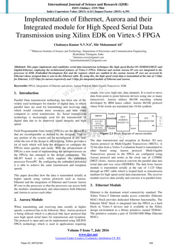
1.12PHYSICAL1.12.1 9009 Board AssemblySize5.5" L x 5.5" W x .5" H(13.97 cm L x 13.97 cm W x 1.24 cm H)(See Figure 1-1)MaterialPC Board - FR406 Flame resistant FiberglassComponents - RoHS compliantConstructionLead FreeWeight0.35 lbs (0.14 kg)TemperatureOperatingStorage-10 C to 55 C-40 C to 70 CHumidity0-90% RH without condensationPower5 0.2 Vdc or 5.5 to 15 Vdc @ 400 mAConnectorsEthernetRJ45GPIBStandard 24-pin IEEE Conector with metric lock studsSerialCinch DE-9S female connector with lock studsUSBUSB 'B' typeLEDs (J4)ICS P/N 902279 or AMP 4-640440-0Power (P2)ICS P/N 902323 or AMP 640440-21-151
1 Figure 1-1 9009 Outline Dimensions1-16
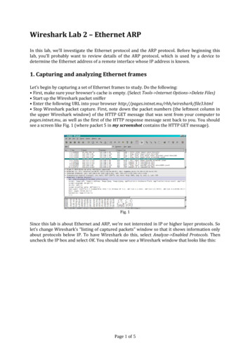
1.12.2 9099 MiniboxSize7.45" L x 5.57" W x 1.52" H(18.92 cm L x 14.15 cm W x 3.86 cm H)(See Figure 1-2)MaterialPC Board - FR406 Flame resistant FiberglassComponents - RoHS compliantConstructionLead FreeWeight3 lbs (1.4 kg) including adapterTemperatureOperatingStorage-10 C to 55 C-40 C to 70 CHumidity0-90% RH without condensationPower9 to 32 Vdc @ 3.5 VAConnectorsEthernetRJ-45SerialCinch DE-9P male connector with lock studs1-171
Figure 1-21-18End View14.15 cm.254cm3.86cmSide View18.92 cm0.95 cmmaxconnector19099 Outline Drawing
1.13CERTIFICATIONS OR APPROVALSEMI/RFIMeets limits for part 15, Class A of US FCC Docket 20780and complies with EEC Standards EN 55022; VDE 087822:2011-12 and EN 55024:2010 VDE 0878-24:2010-09.CE Certificate of Compliances reproduced in Figure 1-2.UL/CSA/VDE AC Wall adapter has applicable UL/CSA/VDE and CE approval.1.14INCLUDED ACCESSORIES1202179009/9099 Instruction Manual123038Support CD-ROM with Configuration Program,Documentation, Sample Programs and Utilities.895011Ethernet Crossover Cable (5 feet long)A/RPower adapter with appropriate country plug (9099only)1.15OPTIONAL ACCESSORIES1202178950111142101142111142279009/9099 Instruction ManualEthernet Crossover Cable (5 feet long)Single Small Minibox Rack Mount KitDual Small Minibox Rack Mount KitLarge/Small Minibox Rack Mounting Kit1-191
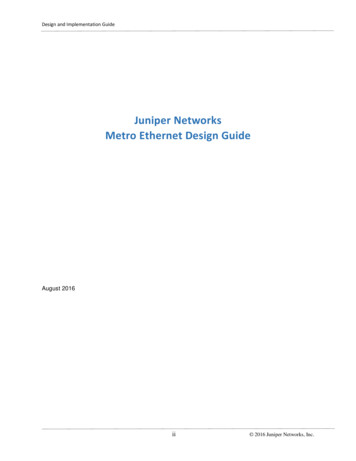
1Figure 1-3 9099 Certificate of Compliance1-20
22Installation2.1INTRODUCTIONThis section provides the user with directions for shipment verification, for installing and configuring the 9009 or 9099 and for connecting to its serial interface.All directions for the 9099 apply to the 9009 unless otherwise stated.2.2UNPACKINGWhen unpacking, check the unit for signs of shipping damage (damaged box,scratches, dents, etc.) If the unit is damaged or fails to meet specifications, notifyICS Electronics or your local sales representative immediately. Also, call thecarrier immediately and retain the shipping carton and packing material for thecarrier’s inspection. ICS will make arrangements for the unit to be repaired orreplaced without waiting for the claim against the carrier to be settled.2.3SHIPMENT VERIFICATIONTake a moment to verify that the following items were included with yourunit:(1)(1)(1)(1)(1)Model 9009 or 9099 Ethernet to Modbus InterfaceAC Power Adapter (9099 only)Instruction ManualSupport CD-ROMEthernet Crossover Cable2-1
2.4INSTALLATION GUIDES2.4.19009 Installation GuideThe following steps should be used as to setup and use the 9009.Review Section 2.9 to select or design the serial cable to the ModbusRTU Slave Device. Change the jumper positions on the 9009 asdirected in Section 2.10 to match the selected signal type.2.Select a convenient location to mount the 9009. The preferred location is flush against the rear panel so that its Ethernet, GPIB and USBconnectors protrude through the rear panel and provide good RFI/EMI suppression. Use the cutouts and mounting dimensions shown inFigure 2-1 for rear panel mounting. Panels thicker than 0.050 incheswill need counterboring to keep the lockstuds in their correct positions.Provide a 0.1 inch clearance between the 9009 and any metal surface.Mount away from any heat producing surface and high frequency, highcurrent cables.150 DIA THRU2 PL1.8421.575.580.450.3125.3005.5004.9001.730DETAIL 'C'4.125DETAIL 'B'DETAIL 00.218.000.0622X ÿ.150.010DETAIL 'A'Figure 2-1DETAIL 'B'9009 Rear Panel Cutouts2-2ÿ.100DETAIL 'C'
3.Use a pair of #22-#24 twisted wires to connect DC power to the 9009’sscrew terminal strip. Set jumper W14 to REG for 5.5 to 15 Vdcpower. Use the P1 position only for 5 Vdc regulated power.4.Connect a PC to one of the 9009’s interfaces and the serial cable tothe Modbus slave device.To use the Ethernet interface, connect a cable to the 9009’s RJ45 connector and follow the directions in Section 2.6 for setting the computerto communicate with the 9099. Use ICS’s VXI-11kybd program ora web browser to access the 9099 at its default IP of 192.168.0.254.See Section 2.6 for detailed instructions.To use the GPIB interface, follow the SCPI Tree in Table 3-2 to configure the unit. Address the 9009 at its default GPIB address of 4. SeeSection 2.7 for detailed instructions.To use the USB interface, install Microsoft’s Virtual COM Port Driverfrom the Support CD as directed in Section 2.8. Initialize the virtualCOM port at 115,200 baud.5.Send the 9009 an *IDN? query to readback its IDN message and toverify communication with the 9009.6.Review the factory settings in Table 1-2 to determine if the baud rateor any other settings need to be changed for the Modbus slave device.Use the ‘D’ command (see Table 3-5) to set the Modbus timeout to1000 for initial tests.7.Obtain the register numbers from the Modbus slave device manufacturer.Use the Modbus read commands in Table 3-5 to query the Modbusslave device to verify communication. Try reading and writing toseveral registers to verify that you have good communication withthe Modbus slave device.8.Check with the Modbus slave device manufacturer to obtain thedevice’s response times. If data is not available, use an oscilloscopeor logic analyzer to measure the Modbus device response time fromthe end of a query to the end of the response message. Try severaldifferent queries. Set the timeout to the manufacturer’s time or to thelongest measured time plus an additional 25 milliseconds. Save thenew setting with the ‘*SAV 0’ command.2-32
9.OEMs may want to change the 9009’s IDN message to report theOEM’s company and model number (See 3.8.15). Save the new IDNmessage and set CAL:LOCK On. The network settings can be leftalone as the end user will need to change them for his company andlocation.2.4.2 9099 Installation Guide2The following steps should be used as to setup and use the 9009.1.Review Section 2.9 to select or design the serial cable to the ModbusRTU Slave Device. Change the jumper positions as directed in Section 2.10 to match the selected signal type.2.Connect the AC adapter, serial cable and the Ethernet cable to the unit.Connect the other end of the Ethernet cable directly to a PC or to thePC through a switch that is not connected to your network as shownin Figure 2-2.Hub or Network SwitchLocal Network ConnectionEthernet CableSerial IORS-232orRS-422/RS-4858099PC with a WindowsOperating SystemFigure 2-2Ethernet toModbusl9099 Modbus Interface9099 with Local or Benchtop Connection3.Follow the directions in Section 2.6 for setting the computer to communicate with the 9099. Use ICS’s VXI-11kybd program to accessthe 9099 at its default IP of 192.168.0.254.4.Send the 9009 an *IDN? query to readback its IDN message and toverify communication with the 9009.5.Review the factory settings in Table 1-2 to determine if the baud rateor any other settings need to be changed for the Modbus slave device.Use the ‘D’ command (see Table 3-5) to set the Modbus timeout to1000 for initial tests.2-4
6.Obtain the register numbers from the Modbus slave device manufacturer.Use the Modbus read commands in Table 3-5 to query the Modbusslave device to verify communication. Try reading and writing toseveral registers to verify that you have good communication withthe Modbus slave device.7.Check with the Modbus slave device manufacturer to obtain thedevice’s response times. If data is not available, use an oscilloscopeor logic analyzer to measure the Modbus device response time fromthe end of a query to the end of the response message. Try severaldifferent queries. Set the timeout to the manufacturer’s time or to thelongest measured time plus an additional 25 milliseconds. Save thenew setting with the ‘*SAV 0’ command.8.Check with the Modbus slave device manufacturer to obtain thedevice’s response times. If data is not available, use an oscilloscopeor logic analyzer to measure the Modbus device response time fromthe end of a query to the end of the response message. Try severaldifferent queries. Set the timeout to the manufacturer’s time or to thelongest measured time plus and additional 25 milliseconds. Save thenew setting. Increase this value if you get Modbus timeout errors.9.Configure the 9099’s network settings for its permanent location.Consult with your network administrator to obtain the correct settingsif it will be placed on the company network. Save the new settings.2.5The Support CD-ROMThe Support CD ROM contains Keyboard, Utility and Example programs forICS’s Interface Products. Interactive Keyboard programs are available for the9009 and 9099’s Ethernet interface and for the 9009’s GPIB and USB Interfaces. These programs let the user send simple commands and queries to theunit without having to write a program. They simplify the checkout processand should be used to test the Modbus slave device communication link.CAUTIONDo not ins
Modbus TCP/IP packets are automatically converted into Modbus RTU packets. The Modbus conversion is transparent and the 9099 does not restrict the Modbus addresses, functions or data but they are restricted by the capabilities of the slave device. Response data from the slave device is returned to the sender as a TCP/IP response packet.