Transcription
Do-It-Yourself Eye Tracker: How Wide Viewing Angle Should theEye Tracking Cover?Michal Kowalik Supervised by: Radoslaw Mantiuk†Faculty of Computer ScienceWest Pomeranian University of Technology in SzczecinPolandAbstractIn the paper we research the relations between the eyetracker accuracy and the human view angle. We measurethe accuracy of the gaze point estimation for a typical andwide view angles and discuss limits of the field of viewcovered by an eye tracker. The measurements are capturedduring perceptual experiments with human observers. Webuilt our own construction of eye tracker based on thepupil-detection technique. We used this eye tracker, calledDo-It-Yourself, in the experimental hardware setup.Keywords: eye tracking,eye tracker hardware,view angleestimation,subjective experimentsing view angles. The hardware setup used during experiments is based on the Do-It-Yourself (DIY) eye tracker.We built this low cost eye tracker to gain full control overthe eye tracking pipeline. The DIY eye tracker is controlled by the open source software available in Internet.In Section 2 presents basic terminology and classification of eye tracking techniques. The DIY eye tracker construction is depicted in Section 3. In Section 4 we presentalgorithms used for the gaze point computation and definethe eye tracker accuracy concept. In Section 5 experimental procedure is described together with the results discussion. We conclude in Section 6.21IntroductionEye tracking devices determine the position of the eye inspace and compute position of a gaze point and a gazedirection. This information is utilised in science and technology, e.g. to test peoples’ preferences concerning advertisement, or to control computer via the eye tracker interface, etc.The progress in technology increases availability ofcomputer monitors with large diagonals. They cover widerviewing angle and strengthen impression of the visualisation realism. Most probably, we can expect a display thatcovers the whole 180 degrees of human visual angle inthe near future. The eye tracking technology must be adjusted to these parameters. However, other limitations ofHuman Visual System (HVS), like foveal vision, also influence the eye tracker operation.The main objective of the project is to determine howwide viewing angle should cover eye tracker. In the paperwe measure accuracy of eye tracker for small and largeview angles. We determine the limits of accuracy resultingfrom eye tracker hardware design and possibilities of gazeestimation algorithms.We conduct perceptual experiments to measure eyetracker accuracy for a number of observers and for increas kkowalik@wi.zut.edu.pl† rmantiuk@wi.zut.edu.plBackground and previous worksThe tracking of viewing direction is known in science formany years. With eye tracking techniques we are able toidentify the place which a man is looking at. This discipline deals with the measurement, recording and analyzing data about the location and movements of the eyeballs.The results of the eye tracker work is the point of regard.A subset of the points of regard is known as an area of interest (region of interest, ROI). Science knows eye tracking analog methods for example contact lenses [13] orelectro-oculogram [1]. These methods are invasive andcome into a strong interaction with the user. Modern eyetracking systems use the image of eye obtained by videoequipment to calculate the point of regard. They are muchmore comfortable for participants than the analogue methods. We distinguish two main approaches in the designingprocess of video based eye-tracking systems [6, 5]: mobile - the camera is mounted on the head or remote - thecamera is located near the monitor. An example of a remote system consists of a camera placed centrally underthe monitor and infrared sources. The mobile system consists of glasses or a helmet on users head with mountedcameras that will record the movements of an eye.Eye tracking systems are divided into working on theeye images grabbed in visible light [10] or infrared light,based on the image of one eye [15] or stereoscopic vision[4].The infra-red eye apparition allows to use three characteristic occurrences: the effect of the dark pupil, the effectProceedings of CESCG 2011: The 15th Central European Seminar on Computer Graphics (non-peer-reviewed)
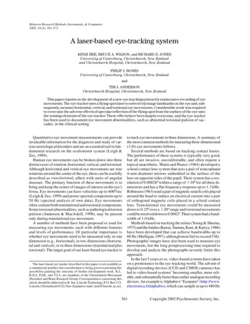
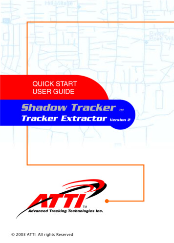
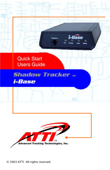
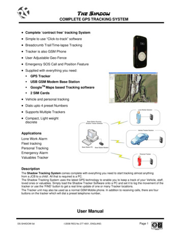
of the bright pupil and the corneal reflection. In the firstcase, the pupil of the eye looks like a dark disk surroundedby a bright ring. In the second case the pupil is bright. Thecorneal reflection is a flash located on the surface of theeye. [6]Figure 2: DIY Eye Tracking setup.Figure 1: Appearance of human eye in infrared light:A) dark pupil and corneal reflection, B) bright pupil.The changes analysis of the vector connecting the centreof the pupil and corneal reflection is a classic example ofthe remote eye tracking method. Assuming that the eye isa sphere and rotates around its own centre and camera withinfrared source is stationary then a corneal reflection position is unchanged. Also corneal reflection (CR) stays inthe same position regardless of the rotation of the eyeball.In this case corneal reflection can be used as a referencepoint. The centre of the pupil (or iris) with a corneal reflection create a vector which is mapped to the coordinatesof the screen during the calibration process(estimation ofgaze point). This solution is non-invasive and allows userto small head movements. [12]. The remote methods divide into: based on changes of the pupil - eye corner vector[19], mapping of four corneal reflections [17, 18, 7] andbased on the three-dimensional model of the eye [15].Tracking pupil centre is a method used in mobile eyetrackers (mounted on the head). It uses dark pupil, thresholding and model fitting method. The position of pupilcentre is compensated with parameters derived in the calibration process. The result is an estimated point of gaze[11, 16]. The algorithms which works in the visible lightuse the centre of the iris to calculate regard point.The mobile eye tracking systems are less comfortablein use than the remote systems. Their advantage is thatwith proper implementation and hardware configurationthey are not limited only to test items on the screen butallow us to operate in the real world.3DIY ET consists of two main parts: eye tracking glassesand computer with ITU Gaze Tracker software. The construction of the eye gaze tracking glasses was based onarticles [14, 3, 9].The glasses are made of off-the-shelfcomponent (Fig. 3).The main part of glasses is the capture module. It is responsible for providing an image ofthe eye to the computer. This module was created by using the Microsoft LifeCam VX-1000 and VX-6000. Wemounted a suitable filter in camera lens that allows capturing images in infrared light. The glasses are connectedto a computer via USB port. Based on the USB technical specification a infra-red illumination system was integrated with the capture module. The infra-red LEDs arelocated on the capture module and supplied by USB cable. This solution is very practical. The glasses provide apicture of an eye to the computer. Then supported application computes the point of gaze and returns it in the formof coordinates (X,Y). The coordinates are stored in LOGfile or transferred directly to another application via clientserver. ITU Gaze Tracker [2] is application designed in ITUniversity of Copenhagen with open source licence 1 .Do-it-yourself Eye TrackerIn our project was created a Do-it-yourself Eye Trackerstation (DIY ET). The main goal of the project was to create inexpensive and simply in construction eye trackingtool. DIY ET base on self constructed eye gaze trackingglasses supported by open source eye tracking application.DIY ET belongs to the group of head mounted eye trackers. It works in infra-red spectrum using dark pupil effects. The point of gaze is calculated by the position ofpupil centre.Figure 3: DIY eye tracker.4Evaluation of eye tracker accuracyIn this section we discuss accuracy of eye tracking systems. The eye tracker precision is defined by degrees ofvisual angle. In main part, the tested accuracy depends1 http://www.gazegroup.org/Proceedings of CESCG 2011: The 15th Central European Seminar on Computer Graphics (non-peer-reviewed)
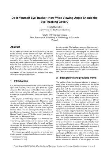
on working of the constructed eye tracker. Besides the eyetracker inaccuracy there are other external sources of error.4.1Human field of viewThe whole human viewing angle is about 180 horizontally and 130 vertically. However, he binocular field ofvision covers only about 120 horizontally. Additionally,The details are read by fovea - a part of the eye located inthe middle of the macula on the retina. It is responsiblefor sharp vision in the middle of the field of view (foveavision). Fovea extends from 1 to 5 angle of human fieldof view.An eye tracker should operate in a view field that donot force head movements. One assumes that it is notmore than 120 of binocular vision. For observer sittingin 50 cm distance from a screen, a display should be up to170 cm wide.4.2Gaze angleThe DIY eye tracker is controlled by the ITU Gaze Trackersoftware. The application estimates the gaze point by mapping the centre of the pupil to screen coordinates usingthe parameters obtained in the calibration process. Imageof eye in infrared light is captured in consecutive frames.The pupil centre is determined and its movements are being tracked.During calibration an observer is asked to look at consecutive target points for a few seconds. The position ofthe eye is recorded and the eye pupil centre is calculated.Correlation between calculated position of the pupil centreand known position of the target points is used to approximate coefficient a0 5 and b0 5 of the polynomial: screenx a0 a1 x a2 y a3 xy a4 x2 a5 y2screeny b0 b1 x b2 y b3 xy b4 x2 b5 y2 ,(1)where (screenx , screeny ) are the gaze point coordinateson the screen, (x, y) are the coordinates of the centre of thepupil [2]. The accuracy of calibration process significantlyaffects error arising during eye tracker operation.The accuracy of eye tracker is determined by indicating the differences in position between the reference pointswith known position and measure gaze points.4.3by the data from the second eye. Another sources of errors encompass inaccuracies of the pupil centre extraction,variation of lighting and of shadows covering the eye.Error factors affecting accuracy of eyetrackerA significant error affecting the accuracy of the gaze pointestimation is the head movement. We use a chin-rest tostabilise the head and increase the DIY eye tracker accuracy. Other solutions utilise algorithms that compensatehead movements [8] or the head trackers. The DIY eyetracker is equipped in one camera and takes image of onlyone eye. The measurement error cannot be compensated5Perception studyThe goal of the tests was to find relation between the accuracy of eye tracker and the view angle of an observer.During tests we use hardware setup based on the DIY eyetracker.5.1Hardware setupOur experimental setup is presented in Figure 4. It consistsof DIY eye tracker controlled via the ITU Gaze Trackersoftware (we used version 2.0 of this software). The software was activated on Acer Aspire 5930 laptop equippedwith a dual-core Intel Core 2 Duo P7350 2.0 GHz andNVIDIA GeForce 9600M GT 512MB graphics card. Thetarget points were displayed on NEC LCD 2690WUXiwith the screen dimensions 55 x 34 cm, and native resolution 1920x1200 pixels (60Hz).To stabilise observes’ heads, we used the chin-restadopted from the ophthalmic slit lamp. The tests were conducted for two distances from eyes to the screen: 50 cmand 30 cm.Figure 4: Hardware setup used during experiments.5.2ParticipantsEleven men with an age from 21 to 34 participated in ourexperiment. Nine participants had normal vision, two ofthem had corrected vision with lens. We asked each participant to repeated the experiment for times for each distance. The whole experiment lasted less than 8 minutes.They were aware that accuracy of the eye tracker is tested,however they do not know details of the experiment.5.3ProcedureThe participants were asked to wear the DIY eye trackerand use the chin-rest to stabilise the head. They lookedat the target points that were displayed on the monitor aswhite circles appearing in random order. The procedurewas repeated for both 50 cm and 30 cm distances by tuningposition of the chin-rest.Proceedings of CESCG 2011: The 15th Central European Seminar on Computer Graphics (non-peer-reviewed)
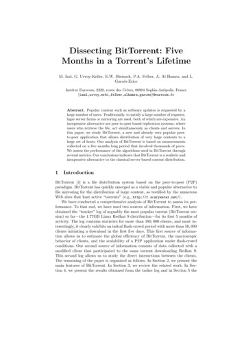
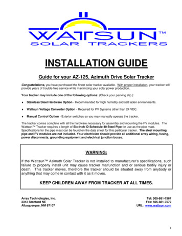
5.4ResultsFigure 6 presents all data collected during the test procedure. Location of the target points is marked by red circle,the observers’ gaze points are depicted as a blue dots. Distribution of gaze points for shorter distance (higher viewangles) is more spread out and does not follow the targetpoint position very well. It results higher accuracy error ofeye tracker. Figure 5 presents box plots of average errorfor sixteen target points. The central mark (red line) indicates median value of the error, the edges of the box arethe 25th and 75th percentiles, the whiskers extend to themost extreme data points not considered outliers. Outliersare plotted individually as red crosses. The blue horizontalline indicates view angle error equal to one degree.For 50cm distance from screen, average error for all target points equals to 1.00deg (with standard deviation equalto 0.95deg) for horizontal direction and 0.9deg (with standard deviation equal to 0.94deg) for vertical direction. Forhigher view angles (30cm distance), the errors increase to3.07deg (standard deviation 2.94deg) and 2.33deg (standard deviation 2.19deg) for horizontal and vertical direction respectively.The results indicate high influence of observers’ viewing angle on eye tracker accuracy. However, we did not notice this relationship for the individual target points. Thereare no regular fluctuations of the error for central and extreme target points.6Conclusions and future workAccuracy of the DIY eye tracker is close to one degree forstandard viewing angles (up to 30 degrees). It is satisfactory result considering low cost of the eye tracker. However, the accuracy decreases to 3 degrees for wide view angles what seems to be unacceptable in most applications.For the wide view angles the eye tracker cannot detectpupil centre accurately. The extreme situation is presentedin Figure 7B where pupil was not detected by image processing software. Combination of eye tracking with headtracking seems to be the solution of this problem. In futurework we plan to build low cost head tracking device andintegrate it with the DIY eye tracker.References[1] Kaufman A., Bandopadhay A., and Shaviv B. Aneye tracking computer user interface. Proc. of theResearch Frontier in Virtual Reality Workshop, IEEEComputer Society Press, pages 78–84, 1993.[2] Javier San Agustin, Henrik Skovsgaarda, and DanWitzner Hansen John Paulin Hansen. Low-cost gazeinteraction: Ready to deliver the promises. CHI,2009. Boston, Massachusetts, USA.[3] J. Babcock, J. Pelz, and J. Peak. The wearable eyetracker: A tool for the study of high-level visualtasks. Proceedings of the Military Sensing SymposiaSpecialty Group on Camouflage, February 2003.[4] Yongqin Cui and Jan M. Hondzinski. Gaze trackingaccuracy in humans: Two eyes are better than one.Neuroscience Letters, 396:257–262, 2006.[5] A.T. Duchowski. Eye Tracking Methodology: Theory and Practice (2nd edition. Springer, London,2007.[6] Riad I. Hammoud. Passive Eye Monitoring - Algorithms, Applications and Experiments. SpringerVerlag Berlin Heidelberg, 2008.[7] You Jin Ko, Eui Chul Lee, and Kang Ryoung Park.A robust gaze detection method by compensatingfor facial movements based on corneal specularities.Pattern Recognition Letters, (29):1474–1485, 2008.[8] Susan M. Kolakowski and Jeff B. Pelz. Compensating for eye tracker camera movement. Proceedingsof the 2006 symposium on Eye tracking research andapplications, pages 79–85, 2006. California.[9] D. Li, J. Babcock, and D.J. Parkhurst. openeyes: Alow-cost head-mounted eye-tracking solution. Proceedings of the ACM Eye Tracking Research and Applications Symposium, 2006.[10] Dongheng Li and Derrick Parkhurst. Open-sourcesoftware for real-time visible-spectrum eye tracking.Human Computer Interaction Program, Iowa StateUniversity, USA, 2006.[11] Dongheng Li, David Winfield, and Derrick J.Parkhurst. Starburst: A hybrid algorithm for videobased eye tracking combining feature-based andmodel-based approaches. Proceedings of the IEEEVision for Human-Computer Interaction Workshopat CVPR, 2005.Figure 7: Detection of the pupil for standard (A) and wideview angle (B).[12] C.H. Morimoto and M. Mimica. Eye gaze trackingtechniques for interactive applications. Computer Vision and Image Understanding, 98:4–24, 2005.Proceedings of CESCG 2011: The 15th Central European Seminar on Computer Graphics (non-peer-reviewed)
[13] D.A. Robinson. A method of measuring eye movements using a scleral search coil in a magnetic field.IEEE Trans. Biomed. Eng., 10, 1963.[14] Jason S.Babcock and Jeff B. Pelz. Building alightweight eyetracking headgear. Eye Tracking Research & Application, 2004.[15] Jian-Gang Wanga, Eric Sungb, and RondaVenkateswarlua. Estimating the eye gaze fromone eye. Computer Vision and Image Understanding, 98:83–103, 2005.[16] David Winfield. Constructing a low-cost mobile eyetracker. 2005.[17] D. Yoo, J. Kim, B. Lee, and M. Chung. Non contacteye gaze tracking system by mapping of corneal reflections. Proc. of the Internat. Conf. on AutomaticFace and Gesture Recognition, pages 94–99, 2002.[18] Dong Hyun Yoo, Myung Jin Chung, Dan Byung Ju,and In Ho Choi. Non-intrusive eye gaze estimationusing a projective invariant under head movement.Proceedings of the 2006 IEEE International Conference on Robotics and Automation Orlando, Florid,May 2006. Florida.[19] J. Zhu and J. Yang. Subpixel eye gaze tracking. Proc.of the 5th IEEE International Conference on Automatic Face and Gesture Recognition, pages 131–136, 2002.Proceedings of CESCG 2011: The 15th Central European Seminar on Computer Graphics (non-peer-reviewed)
3.5distance in degrees between target and gaze )(646,20)(646,406)(646,793) (646,1180) (1273,20) (1273,406) (1273,793) (1273,1180) (1900,20)target points ï (horizontal,veritcal) coordinates in pixels(1900,406) (1900,793) )(646,406)(646,793) (646,1180) (1273,20) (1273,406) (1273,793) (1273,1180) (1900,20)target points ï (horizontal,veritcal) coordinates in pixels(1900,406) (1900,793) (1900,1180)109distance in degrees between target and gaze points876543210Figure 5: Average distance between target and gaze points in degrees of view angle for 16 target directions. Observers’eyes located 50 cm (top) and 30 cm (bottom) from the screen.Proceedings of CESCG 2011: The 15th Central European Seminar on Computer Graphics (non-peer-reviewed)
position of gazeïpoints and targetïpoints2040679311802064612731900position of gazeïpoints and targetïpoints2040679311802064612731900Figure 6: Position of the target-points (red circles) and measured gaze-points (blue dots). Observers’ eyes located 50 cm(top) and 30 cm (bottom) from the screen. Point positions in pixels.Proceedings of CESCG 2011: The 15th Central European Seminar on Computer Graphics (non-peer-reviewed)
3 Do-it-yourself Eye Tracker In our project was created a Do-it-yourself Eye Tracker station (DIY ET). The main goal of the project was to cre-ate inexpensive and simply in construction eye tracking tool. DIY ET base on self constructed eye gaze tracking glasses supported by open source eye tracking application.