Transcription
MODBUS /TCP PROTOCOL GUIDEFor use with:groov EPIC ProcessorsSNAP PAC R-Series ControllersSNAP PAC S-Series ControllersSNAP PAC EB BrainsOPTOEMU SensorsSNAP Ethernet I/O UnitsSNAP Simple I/O UnitsSNAP Ultimate I/O UnitsE1 I/O UnitsE2 I/O UnitsG4EB2/G4D32EB2 BrainsForm 1678-180717—July 201843044 Business Park Drive Temecula CA 92590-3614Phone: 800-321-OPTO (6786) or 951-695-3000Fax: 800-832-OPTO (6786) or 951-695-2712www.opto22.comProduct Support Services800-TEK-OPTO (835-6786) or 951-695-3080Fax: 951-695-3017Email: support@opto22.comWeb: support.opto22.com
Modbus/TCP Protocol GuideForm 1678-180717—July 2018Copyright 2007–2018 Opto 22.All rights reserved.Printed in the United States of America.The information in this manual has been checked carefully and is believed to be accurate; however, Opto 22 assumes noresponsibility for possible inaccuracies or omissions. Specifications are subject to change without notice.Opto 22 warrants all of its products to be free from defects in material or workmanship for 30 months from themanufacturing date code. This warranty is limited to the original cost of the unit only and does not cover installation, labor,or any other contingent costs. Opto 22 I/O modules and solid-state relays with date codes of 1/96 or newer are guaranteedfor life. This lifetime warranty excludes reed relay, SNAP serial communication modules, SNAP PID modules, and modulesthat contain mechanical contacts or switches. Opto 22 does not warrant any product, components, or parts notmanufactured by Opto 22; for these items, the warranty from the original manufacturer applies. Refer to Opto 22 form1042 for complete warranty information.Wired Wireless controllers and brains are licensed under one or more of the following patents: U.S. Patent No(s). 5282222,RE37802, 6963617; Canadian Patent No. 2064975; European Patent No. 1142245; French Patent No. 1142245; British PatentNo. 1142245; Japanese Patent No. 2002535925A; German Patent No. 60011224.Opto 22 FactoryFloor, groov, groov EPIC, Optomux, and Pamux are registered trademarks of Opto 22. Generation 4, groovServer, ioControl, ioDisplay, ioManager, ioProject, ioUtilities, mistic, Nvio, Nvio.net Web Portal, OptoConnect, OptoControl,OptoDataLink, OptoDisplay, OptoEMU, OptoEMU Sensor, OptoEMU Server, OptoOPCServer, OptoScript, OptoServer,OptoTerminal, OptoUtilities, PAC Control, PAC Display, PAC Manager, PAC Project, PAC Project Basic, PAC Project Professional,SNAP Ethernet I/O, SNAP I/O, SNAP OEM I/O, SNAP PAC System, SNAP Simple I/O, SNAP Ultimate I/O, and Wired Wirelessare trademarks of Opto 22.ActiveX, JScript, Microsoft, MS-DOS, VBScript, Visual Basic, Visual C , Windows, and Windows Vista are either registeredtrademarks or trademarks of Microsoft Corporation in the United States and other countries. Linux is a registeredtrademark of Linus Torvalds. ARCNET is a registered trademark of Datapoint Corporation. Modbus is a registered trademarkof Schneider Electric, licensed to the Modbus Organization, Inc. Wiegand is a registered trademark of Sensor EngineeringCorporation. Allen-Bradley, CompactLogix, ControlLogix, MicroLogix, SLC, and RSLogix are either registered trademarks ortrademarks of Rockwell Automation. CIP and EtherNet/IP are trademarks of ODVA. Raspberry Pi is a trademark of theRaspberry Pi Foundation. The registered trademark Ignition by Inductive Automation is owned by Inductive Automationand is registered in the United States and may be pending or registered in other countries.groov includes software developed by the OpenSSL Project for use in the OpenSSL Toolkit. (http://www.openssl.org)All other brand or product names are trademarks or registered trademarks of their respective companies or organizations.Opto 22Automation Made Simple.iiModbus/TCP Protocol Guide
Table of ContentsChapter 1: Introduction . . . . . . . . . . . . . . . . . . . . . . . . . . . . . . . . . . . . . . . . . . . . . . . . . . . . . . . . .1About This Guide . . . . . . . . . . . . . . . . . . . . . . . . . . . . . . . . . . . . . . . . . . . . . . . . . . . . . . . . . . . . . . . . . . . . . . . . . . . . . . . . . . 1Notes on Specific Products . . . . . . . . . . . . . . . . . . . . . . . . . . . . . . . . . . . . . . . . . . . . . . . . . . . . . . . . . . . . . . . . . . . . 1Before You Begin . . . . . . . . . . . . . . . . . . . . . . . . . . . . . . . . . . . . . . . . . . . . . . . . . . . . . . . . . . . . . . . . . . . . . . . . . . . . . 2Contents . . . . . . . . . . . . . . . . . . . . . . . . . . . . . . . . . . . . . . . . . . . . . . . . . . . . . . . . . . . . . . . . . . . . . . . . . . . . . . . . . . . . . 2Other Guides You May Need . . . . . . . . . . . . . . . . . . . . . . . . . . . . . . . . . . . . . . . . . . . . . . . . . . . . . . . . . . . . . . . . . . 2For Help . . . . . . . . . . . . . . . . . . . . . . . . . . . . . . . . . . . . . . . . . . . . . . . . . . . . . . . . . . . . . . . . . . . . . . . . . . . . . . . . . . . . . . . . . . . 3About Opto 22 Devices. . . . . . . . . . . . . . . . . . . . . . . . . . . . . . . . . . . . . . . . . . . . . . . . . . . . . . . . . . . . . . . . . . . . . . . . . . . . . 3Opto 22 Devices as Modbus Master . . . . . . . . . . . . . . . . . . . . . . . . . . . . . . . . . . . . . . . . . . . . . . . . . . . . . . . . . . . . 4Communication Example . . . . . . . . . . . . . . . . . . . . . . . . . . . . . . . . . . . . . . . . . . . . . . . . . . . . . . . . . . . . . . . . . . . . . 4Overview of Modbus Communication. . . . . . . . . . . . . . . . . . . . . . . . . . . . . . . . . . . . . . . . . . . . . . . . . . . . . . . . . . . . . . . 5Understanding Opto 22 and Modbus Differences . . . . . . . . . . . . . . . . . . . . . . . . . . . . . . . . . . . . . . . . . . . . . . . 6Function Codes Supported . . . . . . . . . . . . . . . . . . . . . . . . . . . . . . . . . . . . . . . . . . . . . . . . . . . . . . . . . . . . . . . . . . . . 6Report Slave ID Function Code . . . . . . . . . . . . . . . . . . . . . . . . . . . . . . . . . . . . . . . . . . . . . . . . . . . . . . . . . . . 6Communication Packet . . . . . . . . . . . . . . . . . . . . . . . . . . . . . . . . . . . . . . . . . . . . . . . . . . . . . . . . . . . . . . . . . . . . . . . 7Exception Errors . . . . . . . . . . . . . . . . . . . . . . . . . . . . . . . . . . . . . . . . . . . . . . . . . . . . . . . . . . . . . . . . . . . . . . . . . . . . . . 7Chapter 2: Configuring I/O for Modbus/TCP . . . . . . . . . . . . . . . . . . . . . . . . . . . . . . . . . . . . . 9Introduction . . . . . . . . . . . . . . . . . . . . . . . . . . . . . . . . . . . . . . . . . . . . . . . . . . . . . . . . . . . . . . . . . . . . . . . . . . . . . . . . . . . . . . . 9Module and channel Positions on I/O Units. . . . . . . . . . . . . . . . . . . . . . . . . . . . . . . . . . . . . . . . . . . . . . . . . . . . . . . . . . 9groov I/O Units . . . . . . . . . . . . . . . . . . . . . . . . . . . . . . . . . . . . . . . . . . . . . . . . . . . . . . . . . . . . . . . . . . . . . . . . . . . . . . 10SNAP I/O Units . . . . . . . . . . . . . . . . . . . . . . . . . . . . . . . . . . . . . . . . . . . . . . . . . . . . . . . . . . . . . . . . . . . . . . . . . . . . . . 11SNAP Example 1: Reading/Writing Digital Channel States to Coils and Inputs . . . . . . . . . . . . . . 11SNAP Example 2: Reading/Writing Analog Channel Values to Input and Holding Registers . . 12E1 and E2 I/O Units . . . . . . . . . . . . . . . . . . . . . . . . . . . . . . . . . . . . . . . . . . . . . . . . . . . . . . . . . . . . . . . . . . . . . . . . . . 13E1 Example: Reading/Writing Digital Channel States to Coils and Inputs . . . . . . . . . . . . . . . . . . . 14E2 Example: Reading/Writing Analog Channel Values to Input and Holding Registers . . . . . . . 15G4EB2 I/O Units . . . . . . . . . . . . . . . . . . . . . . . . . . . . . . . . . . . . . . . . . . . . . . . . . . . . . . . . . . . . . . . . . . . . . . . . . . . . . 15G4EB2 brains with G4 modules . . . . . . . . . . . . . . . . . . . . . . . . . . . . . . . . . . . . . . . . . . . . . . . . . . . . . . . . . . 15G4EB2 brains with Quad Pak modules . . . . . . . . . . . . . . . . . . . . . . . . . . . . . . . . . . . . . . . . . . . . . . . . . . . . 16Configuring I/O Channels. . . . . . . . . . . . . . . . . . . . . . . . . . . . . . . . . . . . . . . . . . . . . . . . . . . . . . . . . . . . . . . . . . . . . . . . . . 17Configuring I/O Channels for groov I/O Units . . . . . . . . . . . . . . . . . . . . . . . . . . . . . . . . . . . . . . . . . . . . . . . . . . 17groov I/O module and channel types . . . . . . . . . . . . . . . . . . . . . . . . . . . . . . . . . . . . . . . . . . . . . . . . . . . . . 18Example of Configured groov I/O Channels for Modbus . . . . . . . . . . . . . . . . . . . . . . . . . . . . . . . . . . . 19Modbus/TCP Protocol Guideiiiiii
Configuring I/O Channels for SNAP Analog/Digital I/O Units . . . . . . . . . . . . . . . . . . . . . . . . . . . . . . . . . . .SNAP I/O Channel Types . . . . . . . . . . . . . . . . . . . . . . . . . . . . . . . . . . . . . . . . . . . . . . . . . . . . . . . . . . . . . . . .Examples of Configured SNAP I/O Channels for Modbus . . . . . . . . . . . . . . . . . . . . . . . . . . . . . . . . . .Configuring I/O Channels for SNAP Digital-Only I/O Units . . . . . . . . . . . . . . . . . . . . . . . . . . . . . . . . . . . . . .Using I/O Channel Features . . . . . . . . . . . . . . . . . . . . . . . . . . . . . . . . . . . . . . . . . . . . . . . . . . . . . . . . . . . . . . . . . . . . . . .groov and SNAP Digital I/O Channel Features . . . . . . . . . . . . . . . . . . . . . . . . . . . . . . . . . . . . . . . . . . . . . . . . .Latches . . . . . . . . . . . . . . . . . . . . . . . . . . . . . . . . . . . . . . . . . . . . . . . . . . . . . . . . . . . . . . . . . . . . . . . . . . . . . . . .Counters on groov I/O . . . . . . . . . . . . . . . . . . . . . . . . . . . . . . . . . . . . . . . . . . . . . . . . . . . . . . . . . . . . . . . . . .Counters on SNAP I/O . . . . . . . . . . . . . . . . . . . . . . . . . . . . . . . . . . . . . . . . . . . . . . . . . . . . . . . . . . . . . . . . . .groov and SNAP Analog I/O Channel Features . . . . . . . . . . . . . . . . . . . . . . . . . . . . . . . . . . . . . . . . . . . . . . . . .Scaling . . . . . . . . . . . . . . . . . . . . . . . . . . . . . . . . . . . . . . . . . . . . . . . . . . . . . . . . . . . . . . . . . . . . . . . . . . . . . . . .Minimum and Maximum Values . . . . . . . . . . . . . . . . . . . . . . . . . . . . . . . . . . . . . . . . . . . . . . . . . . . . . . . . .Offset and Gain . . . . . . . . . . . . . . . . . . . . . . . . . . . . . . . . . . . . . . . . . . . . . . . . . . . . . . . . . . . . . . . . . . . . . . . . .E1 Digital Channel Features . . . . . . . . . . . . . . . . . . . . . . . . . . . . . . . . . . . . . . . . . . . . . . . . . . . . . . . . . . . . . . . . . .Latches . . . . . . . . . . . . . . . . . . . . . . . . . . . . . . . . . . . . . . . . . . . . . . . . . . . . . . . . . . . . . . . . . . . . . . . . . . . . . . . .Counters . . . . . . . . . . . . . . . . . . . . . . . . . . . . . . . . . . . . . . . . . . . . . . . . . . . . . . . . . . . . . . . . . . . . . . . . . . . . . . .E2 Analog Channel Features . . . . . . . . . . . . . . . . . . . . . . . . . . . . . . . . . . . . . . . . . . . . . . . . . . . . . . . . . . . . . . . . .Scaling E2 Analog Channels . . . . . . . . . . . . . . . . . . . . . . . . . . . . . . . . . . . . . . . . . . . . . . . . . . . . . . . . . . . . .Minimum and Maximum Values . . . . . . . . . . . . . . . . . . . . . . . . . . . . . . . . . . . . . . . . . . . . . . . . . . . . . . . . .Offset and Gain . . . . . . . . . . . . . . . . . . . . . . . . . . . . . . . . . . . . . . . . . . . . . . . . . . . . . . . . . . . . . . . . . . . . . . . . .A Note on Analog Counts . . . . . . . . . . . . . . . . . . . . . . . . . . . . . . . . . . . . . . . . . . . . . . . . . . . . . . . . . . . . . . .202028282829292930303031313131313232323232Chapter 3: The Modbus Memory Map . . . . . . . . . . . . . . . . . . . . . . . . . . . . . . . . . . . . . . . . . . 33Introduction . . . . . . . . . . . . . . . . . . . . . . . . . . . . . . . . . . . . . . . . . . . . . . . . . . . . . . . . . . . . . . . . . . . . . . . . . . . . . . . . . . . . . . 33Coils number . . . . . . . . . . . . . . . . . . . . . . . . . . . . . . . . . . . . . . . . . . . . . . . . . . . . . . . . . . . . . . . . . . . . . . . . . . . . . . . . . . . . . 33Inputs . . . . . . . . . . . . . . . . . . . . . . . . . . . . . . . . . . . . . . . . . . . . . . . . . . . . . . . . . . . . . . . . . . . . . . . . . . . . . . . . . . . . . . . . . . . . 35Input Registers . . . . . . . . . . . . . . . . . . . . . . . . . . . . . . . . . . . . . . . . . . . . . . . . . . . . . . . . . . . . . . . . . . . . . . . . . . . . . . . . . . . 36Holding Registers . . . . . . . . . . . . . . . . . . . . . . . . . . . . . . . . . . . . . . . . . . . . . . . . . . . . . . . . . . . . . . . . . . . . . . . . . . . . . . . . . 37Notes for All Analog Modules. . . . . . . . . . . . . . . . . . . . . . . . . . . . . . . . . . . . . . . . . . . . . . . . . . . . . . . . . . . . . . . . . . . . . . 39Analog Module Register Table . . . . . . . . . . . . . . . . . . . . . . . . . . . . . . . . . . . . . . . . . . . . . . . . . . . . . . . . . . . . . . . 39Change in Reporting Analog Counts for E2 . . . . . . . . . . . . . . . . . . . . . . . . . . . . . . . . . . . . . . . . . . . . . . . . . . . . 40Notes for groov I/O and SNAP High-Density Digital (HDD) Modules. . . . . . . . . . . . . . . . . . . . . . . . . . . . . . . . . . 40groov I/O and High-Density Digital Module Register Table . . . . . . . . . . . . . . . . . . . . . . . . . . . . . . . . . . . . . 40Chapter 4: Accessing Other Data . . . . . . . . . . . . . . . . . . . . . . . . . . . . . . . . . . . . . . . . . . . . . 43Introduction . . . . . . . . . . . . . . . . . . . . . . . . . . . . . . . . . . . . . . . . . . . . . . . . . . . . . . . . . . . . . . . . . . . . . . . . . . . . . . . . . . . . . . 43Why Access Other Data? . . . . . . . . . . . . . . . . . . . . . . . . . . . . . . . . . . . . . . . . . . . . . . . . . . . . . . . . . . . . . . . . . . . . . 43Accessible Data . . . . . . . . . . . . . . . . . . . . . . . . . . . . . . . . . . . . . . . . . . . . . . . . . . . . . . . . . . . . . . . . . . . . . . . . . . . . . 43Modbus Master Requirements . . . . . . . . . . . . . . . . . . . . . . . . . . . . . . . . . . . . . . . . . . . . . . . . . . . . . . . . . . . . . . . 44Determining Modbus Unit ID and Register . . . . . . . . . . . . . . . . . . . . . . . . . . . . . . . . . . . . . . . . . . . . . . . . . . . . . . . . . 44Finding OptoMMP Memory Map Addresses . . . . . . . . . . . . . . . . . . . . . . . . . . . . . . . . . . . . . . . . . . . . . . . . . . . 44Alternative method (not available for groov EPIC) . . . . . . . . . . . . . . . . . . . . . . . . . . . . . . . . . . . . . . . . . 44Converting OptoMMP Memory Map Addresses . . . . . . . . . . . . . . . . . . . . . . . . . . . . . . . . . . . . . . . . . . . . . . . 46Example: Reading an OptoMMP Memory Map Address . . . . . . . . . . . . . . . . . . . . . . . . . . . . . . . . . . . 48Example: Writing to an OptoMMP Memory Map Address . . . . . . . . . . . . . . . . . . . . . . . . . . . . . . . . . 48Index . . . . . . . . . . . . . . . . . . . . . . . . . . . . . . . . . . . . . . . . . . . . . . . . . . . . . . . . . . . . . . . . . . . . . . . 49ivModbus/TCP Protocol Guide
Chapter 11: IntroductionABOUT THIS GUIDEThis guide shows you how to use Modbus/TCP to communicate with Opto 22 groov EPIC and SNAPEthernet-based controllers and I/O units. The following Opto 22 products can communicate usingModbus/TCP:I/O units with the following 4SNAP-UP1-D64Standalone SNAP-PAC-S2SNAP-PAC-S2-WEnergy monitoring Notes on Specific ProductsOpto 22’s groov Box and groov Server also communicate with Modbus/TCP devices, but this guide doesnot apply to them. This guide discusses Opto 22 products that act as a Modbus slave; groov View in the Boxand Server acts as a Modbus master. For information about using Modbus/TCP devices with a groov Viewmaster, see form 2027, groov View User’s Guide.Modbus/TCP Protocol Guide11
ABOUT THIS GUIDEThe groov EPIC processor (GRV-EPIC-PR1) acts as a Modbus slave, and this guide covers how to use EPIC asa Modbus slave. However, groov View running on the EPIC processor acts as a Modbus master; for instructionson using Modbus/TCP devices with a groov View master, see the groov View User’s Guide.For energy monitoring units, this guide is only a reference. Find primary information for Modbuscommunication in form 1958, OptoEMU Sensor Communication Guide.Before You BeginThis guide assumes that you already understand Modbus/TCP programming and communications. Use thisguide in conjunction with the Modbus/TCP specification, available at http://www.modbus.org/specs.php. TheModbus Protocol Reference Guide may also be useful; at the time this guide was written it was available fromSchneider Electric ersion-J/?reference PIMBUS300IMPORTANT: Before you start, be sure to read form 2011, the Using Modbus Devices with Opto 22 Productstechnical note, available on our website. The technical note will help you get started with Modbus andtroubleshoot communication.ContentsThis guide includes the following:Chapter 1: Introduction—(this chapter) Supported Modbus function codes, communication packet, andexception codes, as well as details about this guide and Opto 22 Product Support.Chapter 2: Configuring I/O for Modbus/TCP—How to configure and use input/output (I/O) channels andchannel features with Modbus/TCP.Chapter 3: The Modbus Memory Map—Coils, inputs, input registers, and holding registers used by mostOpto 22 devices.Chapter 4: Accessing Other Data—Ways to access data not included in coils, inputs, and registers.Other Guides You May NeedAs you work with the Opto 22 devices using Modbus/TCP, you may need to refer to the following additionalguides. All are available on our website, www.opto22.com. The easiest ways to locate one are to click the linkbelow or to search on its form number.For this information2See this guideForm #Modbus basics and troubleshootingUsing Modbus Devices with Opto 22 Products2011Installing and using a groov EPIC processorgroov EPIC User’s Guide2267Installing and using SNAP PAC R-series controllersSNAP PAC R-Series Controller User’s Guide1595Installing and using SNAP PAC S-series controllersSNAP PAC S-Series Controller User’s Guide1592Installing and using SNAP PAC brainsSNAP PAC Brain User’s Guide1690Installing and using OPTOEMU SensorsOptoEMU Sensor User’s Guide1932Communicating with OPTOEMU Sensors usingModbus and Modbus/TCPOptoEMU Sensor Communication Guide1958Installing and using E1 and E2 brain boardsE1 and E2 User’s Guide1563Installing and using SNAP Ethernet, SNAP Simple,and SNAP Ultimate I/O unitsSNAP Ethernet-Based I/O Units User’s Guide1460Modbus/TCP Protocol Guide
CHAPTER 1: INTRODUCTIONFor this informationSee this guideForm #Writing custom applications using the OptoMMP protocol over Ethernet; finding OptoMMP memory map OptoMMP Protocol Guideaddresses1465Configuring and working with SNAP PAC controllersand brains using the software tool PAC ManagerPAC Manager User’s Guide1704Configuring and working with both SNAP PAC andlegacy I/O units using the software tool PAC ManagerPAC Manager User’s Guide, Legacy Edition1714FOR HELPIf you have problems using Modbus/TCP with Opto 22 products and cannot find the help you need in thisguide or on our website, contact Opto 22 Product Support.Phone:800-TEK-OPTO (800-835-6786 toll-freein the U.S. and Canada)951-695-3080Monday through Friday,7 a.m. to 5 p.m. Pacific TimeFax:951-695-3017Email:support@opto22.comOpto 22 website:www.opto22.comNOTE: Email messages and phone callsto Opto 22 Product Support aregrouped together and answered in theorder received.When calling for technical support, you can help us help you faster if you can provide the followinginformation to the Product Support engineer: A screen capture of the Help About dialog box showing software product and version (available byclicking Help About in the application’s menu bar). Opto 22 hardware part numbers or models that you’re working with. Firmware version (available in PAC Manager by clicking Tools Inspect). Specific error messages you saw. Version of your computer’s operating system.ABOUT OPTO 22 DEVICESOpto 22 devices that can communicate using Modbus/TCP include Ethernet-based I/O units, SNAP PACstandalone controllers, OptoEMU Sensor energy monitoring units, and groov products.The term I/O unit refers to one Opto 22 mounting rack or chassis populated with I/O modules and an I/Oprocessor (on-the-rack controller, brain, or brain board; see processor part numbers on page 1). Each I/Omodule can contain 1 to 32 I/O channels, depending on the module.Using Modbus/TCP, you can send data to and from each of these I/O channels using the communicationmethod described in this chapter. The coils, inputs, and registers you use for I/O channel data are described inChapter 3: The Modbus Memory Map.Modbus/TCP Protocol Guide3
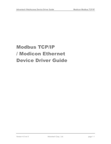
ABOUT OPTO 22 DEVICESOpto 22 Ethernet-based devices use a memory-mapped protocol (OptoMMP), which is based on theIEEE 1394 standard. The coils, inputs, and registers described in Chapter 3: The Modbus Memory Map aremapped to areas within the I/O processor’s memory map.Although the most common use for communication between Modbus systems and Opto 22 systems issending and receiving I/O channel data on an I/O unit, you may also need to obtain other data, from either anI/O unit or a controller. This other data, such as Scratch Pad data, exists in the I/O unit’s or controller’s memorymap and can be accessed by following the steps in Chapter 4: Accessing Other Data.In all these cases the Opto 22 device acts as the Modbus slave.Opto 22 Devices as Modbus MasterThis guide covers the use of Opto 22 devices as Modbus slaves. Opto 22 groov EPIC processors, SNAPPAC controllers, and OptoEMU Sensor energy monitoring units can also act as a Modbus master. groov Viewsoftware in groov EPIC, the groov Box, and groov Server for Windows always acts as a Modbus master. For groov View, see form 2027, the groov View User’s Guide. For OptoEMU Sensors, see form 1958, OptoEMU Sensor Communication Guide. For Opto 22 EPIC processors and SNAP PAC controllers, download a free integration kit from our website,www.opto22.com. Choose the Modbus integration kit you need based on your controller and network.Before you begin, be sure to read form 2011, the Using Modbus Devices with Opto 22 Products technical note.Communication ExampleThe diagram on the following page shows an example of how an Opto 22 system might communicate with aModbus system. This is just one example; many other configurations are possible.In this example, the SNAP-PAC-S1 standalone controller runs a PAC Control strategy that monitors and controlsthe I/O units and all the I/O channels on them. Simultaneously, the Modbus system can exchange data withthe Opto 22 system.Because the two Ethernet network interfaces on the SNAP-PAC-S1 are independent interfaces with separate IPaddresses, the Opto 22 control network can be segmented from the computer network. This example showsthis type of segmentation, as the PC is attached to Ethernet switch #1 and the control network is on Ethernetswitch #2.Because the Modbus/TCP hardware is also on switch #2, it can send data to and from every I/O unit shown. Inthis example the Modbus/TCP software running on the PC, attached to switch #1, can access data only fromthe controller; for instance, it might access data placed in the controller’s Scratch Pad by the PAC Controlstrategy.CAUTION: If you use PAC Control, be careful that Modbus writes to I/O channels don’t conflict with strategy logic.We recommend our free Modbus Integration Kit for PAC Control (part number PAC-INT-MB), available from theOpto 22 website .If you are not using PAC Control, Modbus/TCP hardware or software on the same network segment as I/Ounits can provide full control for I/O channels.4Modbus/TCP Protocol Guide
CHAPTER 1: INTRODUCTIONModbus Communication ExampleModbus/TCPsoftwareEthernet switch #1SNAP-PAC-S1controller (runs aPAC Controlstrategy to controlall I/O units)Ethernet switch #2SNAP-PAC-R1 I/O unitModbus/TCPhardwareE1 I/O unitSNAP-PAC-R1 I/O unitE2 I/O unitSNAP-ENET-S64 I/O unitSNAP-ENET-S64 I/O unitOVERVIEW OF MODBUS COMMUNICATIONCommunicating with Opto 22 Ethernet-based devices using Modbus/TCP requires four basic steps: connect,configure, read/write, and disconnect.When opening a TCP/IP connection to the system, you normally use port 502. (This is the default port; it canbe changed for security reasons using PAC Manager. See form 1704, PAC Manager User’s Guide, for moreinformation.)Opto 22 devices can handle a maximum of eight connections from Modbus masters. (Requires firmware R9.4Bor higher—or, for E1 and E2, firmware R1.2a. Lower firmware versions handle a maximum of twoconnections.)For all coils, inputs, and registers listed in Chapter 3: The Modbus Memory Map, use a slave ID (Unit ID) of 1 forthe device.Modbus/TCP Protocol Guide5
OVERVIEW OF MODBUS COMMUNICATIONUnderstanding Opto 22 and Modbus DifferencesNotice that Opto 22 module and channel numbers on the I/O unit commonly start numbering at 0 (zero),while Modbus coil or input numbers start at 1; so Modbus coil 1 or input 1 usually equals Opto 22 channel 0on the module in position 0 on the rack.Also notice the way Opto 22 uses Modbus registers:Modbus RegistersOpto 22 UseModbus RegistersOpto 22 UseCoilsDigital outputsRegister inputsAnalog inputsInputsDigital inputsHolding registersAnalog outputs and miscellaneousFunction Codes SupportedOpto 22 devices use the Modbus function code plus the register number to map to the appropriate memorymap address in the brain.NOTE: Data on a SNAP PAC standalone controller can be accessed only through advanced Modbus programming.See Chapter 4: Accessing Other Data for information.The following table shows Modbus function codes supported for I/O units. (Function codes for a specific I/Ounit depend on the analog/digital capabilities of the brain.)Modbus FunctionCode (Hex)DefinitionOpto 22 Equivalent01Read coil statusRead digital output02Read input statusRead digital input03Read holding registersRead analog output04Read input registersRead analog input05Force single coilTurn on/off one digital output06Preset single registerWrite one analog output0FForce multiple coilsTurn on/off multiple digital outputs10Preset multiple registersWrite multiple analog outputs11Report slave IDReport hardware and firmware revision levels(See below: “Report Slave ID Function Code” )Report Slave ID Function CodeFunction code 0x11, Report slave ID, returns data bytes as shown in the following table.Bytes 1 and 2 are always in the formats shown. The 0x22 in byte 1 indicates an Opto 22 brain; 0xFF appears inbyte 2 because, since the brain is a slave, it is always running.Byte 1Byte 2Bytes 3–6Bytes 7–10Bytes 11–14Hardware Version*SlaveRunIDIndicator Major Minor A/B/R LetterMajorMinor A/B/R LetterMajorMinor A/B/R el Version*0x01Loader Version*0x01* Hardware, kernel (firmware), and loader versions each include four bytes, indicating:1st byte—major version number2nd byte—minor version number3rd byte—revision type: 0 A (alpha), 1 B (beta), 2 R (release)4th byte—version letter: 0 a, 1 b, 2 c, 3 d, and so onExample: 0x03080200 would indicate version R3.8a6Modbus/TCP Protocol Guide0x010x01
CHAPTER 1: INTRODUCTIONCommunication PacketAs the Modbus/TCP specification requires, Opto 22 devices use a Modbus packet inside a TCP/IP packet. TheModbus checksum is not used; instead, the Ethernet TCP/IP link layer checksum guarantees data. The size ofthe packet is limited to 256 bytes. The packet follows the standard Modbus/TCP format.Note: You can read a maximum of 127 input or holding registers in one command 03 or 04.Exception ErrorsIf an error occurs, standard Modbus exception codes are returned in the Modbus packet. The following table,reprinted from the Modicon Modbus Protocol Reference Guide, shows the Modbus exception codes. If you needmore information, see the Modicon documentation.CodeNameMeaning01ILLEGAL FUNCTIONThe function code received in the query is not an allowable action forthe slave.02ILLEGAL DATAADDRESSThe data address received in the query is not an allowable address forthe slave.03ILLEGAL DATA VALUEA value contained in the query data field is not an allowable value forthe slave.04SLAVE DEVICE FAILUREAn unrecoverable error occurred while the slave was attempting to perform the requested action.05ACKNOWLEDGEThe slave has accepted the request and is processing it, but a long duration of time will be required to do so. This response is returned to preventa timeout error from occurring in the master. The master can next issue aPoll Program Complete message to determine if processing is completed.06SLAVE DEVICE BUSYThe slave is engaged in processing a long-duration program command.The master should retransmit the message later when the slave is free.07NEGATIVEACKNOWLEDGET
ABOUT THIS GUIDE 2 Modbus/TCP Protocol Guide The groov EPIC processor (GRV-EPIC-PR1) acts as a Modbus slave, and this guide covers how to use EPIC as a Modbus slave. However, groov View running on the EPIC processor acts as a Modbus master; for instructions on using Modbus/TCP devices with a groov View master