Transcription
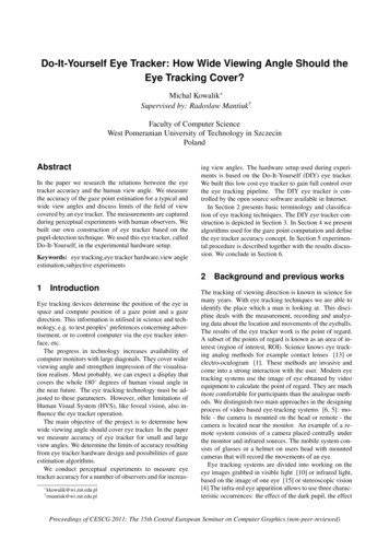
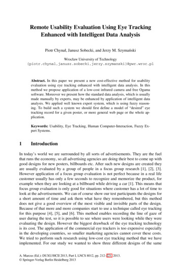
Proceedings of the Federated Conference on Computer ScienceDOI: 10.15439/2016F538and Information Systems pp. 1417–1422ACSIS, Vol. 8. ISSN 2300-5963Enhanced Eye-Tracking Data: a Dual Sensor System forSmart Glasses ApplicationsPaweł Krzyżanowski, Tomasz Kocejko, Jacek Ruminski, Adam BujnowskiGdansk University of Technology, Department of Biomedical Engineering,Faculty of Electronics, Telecommunications and Informatics, PolandEmail: pawkrzyz@pg.gda.pl, tomkocej@pg.gda.pl, jacek.ruminski@pg.gda.pl, bujnows@biomed.eti.pg.gda.plAbstract – A technique for the acquisition of an increasednumber of pupil positions, using a combined sensor consistingof a low-rate camera and a high-rate optical sensor, ispresented in this paper. The additional data are provided bythe optical movement-detection sensor mounted in closeproximity to the eyeball. This proposed solution enables asignificant increase in the number of registered fixation pointsand saccades and can be used in wearable electronicsapplications where low consumption of resources is required.The results of the experiments conducted here show that theproposed sensor system gives comparable results to thoseacquired from a high-speed camera and can also be used in thereduction of artefacts in the output signal.I. INTRODUCTIONTHE rapid development of wearable electronics hasmeant that this technology is ever-present in everydaylife; the number of such applications and solutions forhuman-machine interactions is constantly increasing.However, the miniaturization of these devices and thegrowing array of functionalities require the development ofnew interfaces. For many applications, for example septictype interactions [1], the eye-tracking interface is a veryconvenient option. With just a glance from the user, it ispossible to execute commands. This technology has manypossible applications [2, 3]; however, it is still undercontinuous study [4, 5]. In addition, research to enhancevideo-based gaze tracking is needed to increase both thequality and the amount of data acquired by the system [6] aswell as to increase the speed of real-time processing [7].Since modern wearable electronics like smart glasses aremultitasking devices, the design of interfaces within theconstraints of the processor unit’s computational power is achallenge. In modern eye-tracking interfaces, the cameraframe rate is a factor that can increase the potential numberof applications of the interface. With the advanced imageprocessing required for reliable estimation of eye and gazeThis work has been partially supported by NCBiR, FWF, SNSF,ANR and FNR in the framework of the ERA-NET CHIST-ERA II, ProjecteGLASSES – The interactive eyeglasses for mobile, perceptual computingand by statutory funds from the Faculty of Electronics, Telecommunicationsand Informatics Faculty, Gdansk University of Technology.978-83-60810-90-3/ 25.00 c 2016, IEEE1417position, the eye-tracking interface is the device whichconsumes the majority of the power resources. In addition, aneed for high computational power and the excessive powerconsumption are difficult requirements to fulfil.In gaze-tracking interfaces, it is important to achieve acorrect image acquisition, an accurate calculation of thefixation point and the appropriate processing of these data.In practical applications, the time required by the CPU/GPUto process the data is significant [8] and the reduction of thistime results in lower consumption of power, which is alsoimportant when considering the design of a battery chargingcircuit. It should be emphasized that studies which havepresented new integrated circuits (ICs) have achievedeffective results with software and hardware data processing,but these ICs are not in widespread use [9].Fig. 1 Prototype of the eGlasses platformThe eGlasses (Fig. 1) electronic eyewear is amultisensory platform capable of running on both Linux andAndroid operating systems. The eye-tracking module is oneof the eGlasses input interfaces. It allows operation bygraphic user interface, controlled by gaze, and also providesdata that can be used in interaction with everyday objects.The core elements of the eye-tracking module hardware areinfrared LED-based eye surface lights, the camera thatregisters eye movements (eye camera) and the camera thatregisters the scene images (scene camera). In the currentprototype, the eye-tracking module allows a 30 Hz samplingfrequency at a resolution of 320x240 pixels. This samplingrate significantly decreases for higher resolutions (e.g., it isonly 15 Hz for an image of 640x480 pixels resolution). The
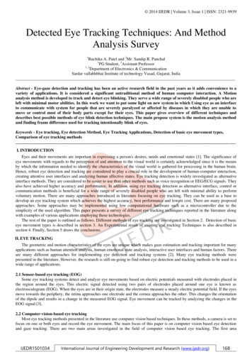
1418PROCEEDINGS OF THE FEDCSIS. GDAŃSK, 2016use of an optical sensor with low power consumption allowsa high frame rate to be maintained, while preserving a highresolution in the eye-tracking camera. This study presents atechnique for increasing the eye-tracker sampling frequencyby combining the low-rate camera with the additional opticalsensor. So far such an idea has been used mostly in nonwearable electronic equipment to minimize errors caused byhead rotation [10].The rest of the paper is organized as follows: Section 2describes the methods, experimental stand and algorithm.The experimental set-up and results are presented in Section3. Section 4 contains a discussion and potential applicationsfor this new concept. Section 5 presents the conclusion.II. METHODS AND MATERIALSThe underlying concept of this research was to use an eyetracking camera and an additional simple optical sensor toincrease the number of registered pupil positions. Theprinciple of operation of the additional sensor was based onmeasurements of eyeball displacements. To evaluate thisidea, a custom-built eye-tracker allowing measurement ofpupil movements with a 180 Hz sampling rate was utilized.The optical sensor was then added to complement the eyetracker. An appropriate test stand was built to conduct theexperiments in a controlled environment.180 Hz. The basic parameters of the eye-tracker arepresented in Table 1.TABLE IBASIC PARAMETERS OF THE EYE TRACKER USEDParameterValueEye-tracking technique:Dark Pupil, Pupil CentreDetectionEye-tracking:Monocular (left eye)Data rate:180 HzAccuracy:0.7 Precision:0.5 Light condition restrictions:NoEye-tracking camera320x240 pxresolution:The eye camera was connected to a PC computer with theeye-tracking software installed and running on Linux OS.The main classes of the eye-tracking software covered eyeand scene camera image acquisition, pupil-detectionalgorithms, video for Linux camera support, gstreamer andopencv camera support and fixation and gaze-trackingalgorithms. The eye-tracking software offered threealgorithms for pupil centre detection; this study wasconducted using the most accurate one, based on theselection of pupil boundary candidate points and ellipsefitting.a)A. Experimental Stand and DataThe experimental hardware equipment consisted of thethree main components: the eye-tracking camera, the opticalmotion sensor, and a model of an eyeball made of plastic.The model was of spherical shape and contained an artificialpupil (Fig. 2).The stand was equipped with two bearing servomotors(HD3688MG) and the frame was constructed using 3Dprinter technology. The construction had two degrees offreedom: horizontal (x) and vertical (y). The servomotorswere controlled by a PWM signal from the microprocessor.This approach allowed independent movement in both the xand y-directions.b)Fig. 2 The 3D frame (Fr) with the eyeball model controlled byservomotors (Sv)The servomotors allowed the eyeball position to bechanged up to 25 times per second. With this frequency itwas possible to simulate saccades that lasted 40 ms. Healthyeye movements were therefore able to be simulated [11].The camera captured the pupil position with a frequency ofFig. 3 Configurations of a) the experimental stand and b) itsimplementationTo track the eyeball motion, the PAN3101, a low costCMOS optical sensor integrated with DSP, was used. The
PAWEL KRZYZANOWSKI ET AL.: ENHANCED EYE-TRACKING DATA: A DUAL SENSOR SYSTEM FOR SMART GLASSES APPLICATIONSDSP serves as an engine for the estimation of nonmechanical motion. The optical navigation technology usedin this optical sensor enabled investigators to measurechanges in position by optically acquiring sequential surfaceimages (frames) and mathematically determining thedirection and magnitude of movement. The current x and ymovements can be read from the registers via a serial port.The sensor required additional optics. The one used in thisresearch (HDNS-2100) allowed application of the sensor at adistance of 7.5 mm from the eyeball model. In fact, this iscurrently a primary impediment to in vivo use of this sensor.However, it appears to be possible to increase the distancebetween the optical sensor and the eyeball, although thiswould require some changes to the angle between themirrors and the focal length of the lens. The IR LED diodepower should also be adjusted in accordance with safetylimits [12]. During experiments, the sampling rate of thesensor was set to 125 Hz. The optical sensor was connectedto the additional PC unit. All data acquired by the sensorswere transferred using the UDP protocol to the externalserver for further integration and processing.There were certain discrepancies in the parametersmeasured by each sensor. The camera was used to acquirepupil positions frame by frame in an absolute coordinatesystem, while the optical sensor measured the total eyeballmovement (total shift between the last two frames). The shiftwas the sum of the movement before and after camerasampling, so the value of this shift had to be splitproportionally between the frames (Fig. 4).14192. Get data from the optical sensor (timestamp, x and ymovement).3. Calculate a new pupil position by adding to theprevious pupil position the scaled shift obtained from theoptical sensor.4. Repeat points 2-3 until new data from the eye-trackeris ready.5. Get data from the eye camera (pupil position andtimestamp t1) and update to a new fixation point.6. Get data from the optical sensor and splitinformation proportionally to time before and aftertimestamp t1.7. Calculate a new pupil position based on data after t1.8. Go to point 2.Fig. 5 Block diagram of the proposed algorithmFig. 4 Output pupil positions and incoming data from both sensors: at apoint (the eye camera) and proportional to a shift in time (the opticalsensor)B. Data Acquisition and Fusion AlgorithmThe concept underlying of this project was to insert a highfrequency signal into a low frequency one (Fig. 5). Thealgorithm developed for this comprised two major parts. Thefirst was a calibration procedure, while the second wasdevoted to calculating the additional pupil positions fromdata registered by the optical sensor, with reference to thosecaptured by the camera. A description of the algorithm is asfollows:1. Start, set the first pupil position from the camera andreset the shift register in the optical sensor (timestamp 0).C. ExperimentsTo evaluate the concept of extending a set of pupilpositions recorded by the eye tracking camera using dataacquired by the optical sensor, several experiments wereconducted. In the first experiment, a set of pupil positionswere recorded over a certain period by both the referenceeye-tracking camera (180 Hz sampling rate) and the opticalsensor (125 Hz sampling rate). This was done in order tocheck the similarities of the paths recorded by the sensors.Pearson correlation coefficients were calculated separatelyfor the x and y coordinates: ̅ ̅ ̅ 2 ̅ 2 ̅̅ ̅ 2̅ 2,(1),(2)where , are the x and y coordinates of a pupilposition, , are the x and y coordinates of the sampleregistered by the optical motion sensor,̅ , ̅ are theaverage values of pupil position samples along the x- and yaxes, and̅ , ̅ are average values of eyeball positionsalong the x- and y-axes, registered by the optical motionsensor.Following this, a set of experiments exploring differentpatterns of movement were performed. Square-shaped
1420PROCEEDINGS OF THE FEDCSIS. GDAŃSK, 2016Vertical pupil position [px]movements (Fig. 7) were used to calculate the properconstant ratio between the measurements from both sensors.A set of pupil positions from the camera was recalculated byusing perspective transformation to compensate for theviewing angle. After calibration, various sequences of theeyeball movement were tested (ellipse, triangle and random)with a fixation duration of between 140 and 530 ms. Eachsession lasted for ten repeated sequences, and themeasurements were stored with a synchronized timestamp.a)Horizontal pupil position [px]Vertical pupil shift [px]b)III. RESULTSThe similarities between the pupil positions recorded bythe camera and the eyeball movement acquired by theoptical sensor are presented in Fig. 6. The calculatedcorrelation between waveforms recorded by the eye cameraat 180 Hz and the optical sensor at 125 Hz were stronglypositive: . .In the next experiment, data square movement wasimplemented to calculate the ratio between sensors. Theresults are presented in Fig. 7 and numerical values are givenin Table 2.Following this, experiments were performed to check fordependencies between the information gain and the signalvariability. The eyeball motion was programmed for fixationduration of 140 ms and data from 30, 10 and 5 Hz camerafrequencies were enhanced by the optical sensor. Thecalculated pupil positions were compared to both referencesignals: the high-speed camera and the theoretical route. Forgreater clarity, the results are presented in Figs. 8-10 and inTable 3. The axes of the coordinate system are pixels (exceptfor the optical sensor figure) and the values plotted are thecentred pupil positions.a)Fig. 6 Similarities between the eyeball movement recorded by thecamera and optical sensor: a) The plot of consecutive pupil centrepositions detected by the eye tracker b) The plot of the eyeball motion(x, y) coordinates detected by the optical sensorThe sampling rates remained the same; 180 Hz for thecamera and 125 Hz for the optical sensor. Next, the original180 Hz raw data were reduced to simulate recording with 5,10, 30 and 60 Hz sampling rates. This allowed the creationof a set of data that could be extended by the optical sensorreadings and which fully corresponded to the reference data.The results were compared to both: the high-speed 180Hzcamera reference as well as the theoretical, programmedideal eyeball movement. The signals from the optical sensor,the camera and the new combined set had different lengths,and all data were therefore resampled to 1ms usinginterpolation. The similarity between signals was checked bycalculating the mean square error: ̂ ,(3) ̂ ,(4)̂̂whereis number of samples, and are signal pupilpositions in the horizontal and vertical dimensions, and and are pupil positions from the reference signal (idealmovement or high speed camera).-5000-30000-1000-100001000-20000Horizontal pupil shift [px]-30000b)Vertical pupilposition [px]Horizontal pupil shift [px]-7000Vertical pupilshift [px]-900013080110130150Horizontal pupil position [px]Fig. 7 Calibration of data from both sensors: a) movement recorded bythe mouse sensor; b) pupil positions recorded by the high-speed cameraafter perspective transformationTABLE IICALCULATED SCALE CONSTANTSNameValueX ratio:4.58*10-3X standard deviation:1.59*10-4Y ratio:2.49*10-3Y standard deviation:2.08*10-5
PAWEL KRZYZANOWSKI ET AL.: ENHANCED EYE-TRACKING DATA: A DUAL SENSOR SYSTEM FOR SMART GLASSES APPLICATIONS1421a)Vertical pupil position [px]Vertical pupil position [px]a)Horizontal pupil position [px]b)Horizontal pupil position [px]Vertical pupil position [px]Vertical pupil position [px]b)Horizontal pupil position [px]Horizontal pupil position [px]c)Vertical pupil shift [px]Vertical pupil position [px]c)Horizontal pupil shift [px]Horizontal pupil position [px]Fig. 10 Enhanced signal after combining data from both sensors. Redsquares are pupil positions from camera, and blue crosses are fixationscalculated by the system a) 30Hz camera showing no new datacompared to the camera system only; b) 10Hz camera signal showingsome curves between points; c) 5Hz camera showing the largestimprovement compared to using only the camera systemFig. 8 Raw data before processing: a) ideal movement from the eyeballmodel; b) pupil positions recorded by the camera; c) eyeball shiftmeasured by the optical sensorVertical pupil position [px]a)Horizontal pupil position [px]Vertical pupil position [px]b)Vertical pupil position [px]In the last experiment (Fig. 11), a random motion wastested and the system also gave additional data where thesampling rate was insufficient.a)Horizontal pupil position [px]Vertical pupil position [px]c)Horizontal pupil position [px]Vertical pupil position [px]b)Horizontal pupil position [px]Horizontal pupil position [px]Fig. 9 The effect of decreasing information during reducing of thecamera sampling rate: a) 30 Hz camera showing good reproduction ofthe signal; b) 10 Hz camera showing sufficient reproduction but withsome information already lost; c) 5 Hz camera showing high distortionof signalFig. 11 Experiment combining data from both sensors: a) Low speedcamera (red squares) and calculated pupil positions (blue ‘x’) fromoptical sensor; b) reference high-speed camera
1422PROCEEDINGS OF THE FEDCSIS. GDAŃSK, 2016Table IIIEXPERIMENT WITH ENHANCED DATA USING THE DUAL SENSOR SYSTEMFixation period: 140 msShape 60 Hz - 180 Hz camShape 60 Hz - ideal moveShape 30 Hz - 180 Hz camShape 30 Hz - ideal moveShape 10 Hz - 180 Hz camShape 10 Hz - ideal moveShape 5 Hz - 180 Hz camShape 5 Hz - ideal moveMSECamera 0.338.8324.4212.65124.0630.71113.25IV. DISCUSSIONThese experiments confirmed the assumption that datacaptured with the eye-tracking camera can be expandedusing additional samples gathered by a faster optical sensor.Some older studies state that the minimum samplingfrequency to record saccades should be 300 Hz [13], butnewer research shows that a 50-60 Hz sampling rate issufficient [14]. The additional data acquired from the opticalsensor (which can be set up to 3 kHz) should be sufficientfor measurement of both fixations and saccades. The systemdeveloped here can be used in applications where a lowcomputing time is required, e.g., in systems containing manyperipherals that involve computational complexity [15].Analytical study of the data obtained by means of the dualsensor system gives the expected results. The eyeballmovement direction changed 9 times per second. When thecamera sampling rate was three times larger than the signalvariability, there was no new information gain aftercombining the data. When the signal fluctuates fast enoughwhen compared to the camera sampling rate, the informationgain increases. This can be used to find the optimal usage ofcomputational resources with an acceptable quality of eyetracking in any mobile device.The additional value of this system emerges from the firstand last experiments conducted (Fig. 6 and Fig. 11). In theserecordings, the camera eye-tracking algorithm shows smallfluctuations or artefacts. In contrast, the optical sensorduring the same timestamp shows no distortions. Thisfeature can be used as redundancy and may result inincreased reliability of the system.V. CONCLUSIONSThe study performed here shows that it is possible toextend the number of pupil positions captured by the camerabased on data provided by a much faster optical sensor. Ahigh level of similarity between the expanded and referencedatasets proves that the proposed algorithm is correct andreliable. The algorithm developed here may influence theimplementation of the eye-tracing procedures utilised inwearable electronic devices such as smart glasses. Thepossibility of extending the number of pupil positions usingthe optical sensor allows for a significant reduction in theCombined 6.169.2815.892.6615.559.0020.57eye-tracking camera sampling rate, and thus enablesreduction of the required computational power and powerconsumption.REFERENCES[1] K. Czuszynski, J. Ruminski, T. Kocejko and J. Wtorek, “Septic safeinteractions with smart glasses in health care,” in Engineering inMedicine and Biology Society, Milan, 2015, pp. 1604-1607,10.1109/EMBC.2015.7318681[2] T. Kocejko, A. Bujnowski and J. Wtorek, “Eye-mouse for disabled,” inHuman-Computer Systems Interaction, Springer Berlin - Heidelberg,2009, pp. 109-122, 10.1109/HSI.2008.4581433[3] T. Kocejko, A. Bujnowski and J. Wtorek, “Complex human computerinterface for LAS patients,” in Human System Interactions, IEEE Press,pp. 272-275, 10.1109/HSI.2009.5090991[4] Z. Yücel, A. Salah and C. Mericli, “Joint attention by gazeinterpolation and saliency,” in Cybernetics vol. 43, 2013, pp. 829-842,10.1109/TSMCB.2012.2216979[5] B. R. Pires, M. Devyver and A. Tsukada, “Unwrapping the eye forvisible-spectrum gaze tracking on wearable devices,” in Applications ofComputer Vision, 2013, pp. 369-376, 10.1109/WACV.2013.6475042[6] F. Li, S. Kolakowski and J. Pelz, “Using structured illumination toenhance video-based eye tracking”, in Image Processing, ICIP, SanAntonio, 2007, pp. 373-376. 10.1109/ICIP.2007.4378969[7] M. Mehrubeoglu, L. M. Pham and H. T. Le, “Real-time eye trackingusing a smart camera,” in Applied Imagery Pattern RecognitionWorkshop (AIPR), IEEE, Washington, 2011, pp. 1-7,10.1109/AIPR.2011.6176373[8] A. Al-Rahayfeh and M. Faezipour, “Enhanced frame rate for real-timeeye tracking using circular Hough transform,” in Systems, Applicationsand Technology Conference, Farmingdale, 2013, pp. 1-6,10.1109/LISAT.2013.6578214[9] D. Kim, J. Cho and S. Lim, “A 5000S/s Single-Chip Smart EyeTracking Sensor”, in: Solid-State Circuits, ISSCC 2008, pp. 46-59,10.1109/ISSCC.2008.4523049[10] D. Beymer and M. Flickner, “Eye gaze tracking using an active stereohead,” in Computer Vision and Pattern Recognition vol.2, Madison,USA, 2003, pp. 451-458, 10.1109/CVPR.2003.1211502[11] W. M. King, S. G. Lisberger and A. F. Fuchs, “Oblique Saccadic EyeMovements of Primates,” in Journal of Neurophysiology vol. 56, 1986,pp. 769-784,[12] ICNIRP guidelines on limits of exposure to laser radiation ofwavelengths between 180 nm and 1,000 μm, in Health Physics 105(3),2013, pp. 271-295.[13] M. Juhola, V. Jantti and I. Pykko, “Effect of sampling frequencies oncomputation of the maximum velocity of saccadic eye movements”, inBiological Cybernetics, Springer-Verlag, 1985, pp. 67-72,10.1007/BF00337023[14] R. Wierts, M. Janssen and H. Kingma, “Measuring Saccade PeakVelocity Using a Low-Frequency Sampling Rate of 50 Hz”, TBME.2008.925290[15] T. Kocejko, J. Ruminsk, J. Wtorek and B. Martin, “Eye tracking withinnear-to-eye display,” in Human System Interactions, Warsaw, 2015, pp.166-172, 10.1109/HSI.2015.7170661
The core elements of the eye-tracking module hardware are infrared LED-based eye surface lights, the camera that registers eye movements (eye camera) and the camera that registers the scene images (scene camera). In the current prototype, the eye-tracking module allows a 30 Hz sampling frequency at a resolution of 320x240 pixels.