Transcription
https://www.halvorsen.blogModbusWith Practical LabVIEW ExamplesHans-Petter Halvorsen
Contents Modbus Modbus in LabVIEW LabVIEW Examples– LabVIEW Coils Examples– LabVIEW Discrete Input Registers Examples– LabVIEW Input Registers Examples– LabVIEW Holding Registers Examples
https://www.halvorsen.blogModbusHans-Petter HalvorsenTable of Contents
What is Modbus? Modbus is a serial communications protocol originallypublished by Modicon (now Schneider Electric) in 1979 foruse with its programmable logic controllers (PLCs). Simple and robust, it has since become a de facto standardcommunication protocol, and it is now a commonlyavailable means of connecting industrial electronic devices The development and update of Modbus protocols hasbeen managed by the Modbus Organization since April2004, when Schneider Electric transferred rights to thatorganization (https://modbus.org) Modbus became the first widely accepted fieldbusstandard.
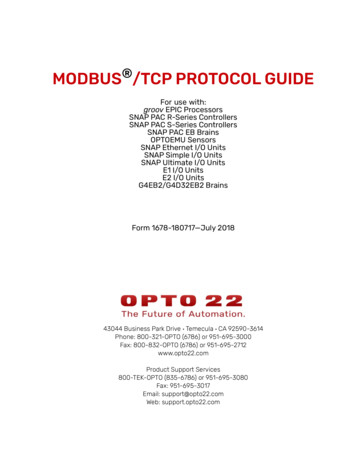
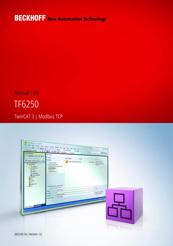
ModbusThe master typically is a PLC (Programmable Logic Controller), PC or DCS (Distributed Control System)PLCRTURTUSCADAMasterDSCProcess MeasurementsSlaveSlaveMasterPCSlaveA remote terminal unit (RTU) is a microprocessor-controlled electronicdevice that interfaces objects in the physical world to a DCS or SCADA SystemSensors and Actuators
The Modbus protocol follows a Master/Slave (Client/Server) architecture where aMaster (Client) transmits a request to a Slave (Server) and waits for the response.Note! The terms “Master” and “Slave” used in Modbus has beenreplaced with the terms “Client” and “Server”. The LabVIEW Modbuspackage still use the old terms, so they will also be used in this Tutorial
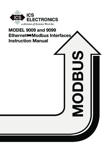
Master/Slave Modbus protocol is defined as a master/slaveprotocol, meaning a device operating as amaster will poll one or more devices operatingas a slave. This means a slave device cannot volunteerinformation; it must wait to be asked for it. The master will write data to a slave device’sregisters and read data from a slave device’sregisters. A register address or register referenceis always in the context of the slave’s registers.
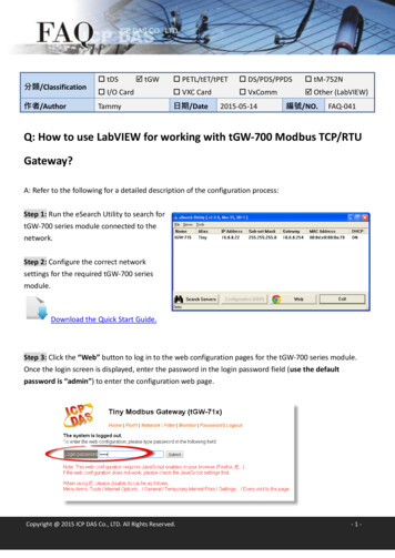
Master/SlaveClientMasterWrite rRead DataData Stored in RegistersModbus protocol is defined as a master/slave protocol, meaning a device operating as a master will pollone or more devices operating as a slave. This means a slave device cannot volunteer information; it mustwait to be asked for it. The master will write data to a slave device’s registers and read data from a slavedevice’s registers. A register address or register reference is always in the context of the slave’s registers.
Modbus Register Types Coil (Discrete Output)– Coils are 1-bit registers, used to control discreteoutputs, Read or Write Discrete Input (Read Only)– 1-bit registers Input Register (Read Only) Holding Register (Read/Write)
Access Levels In SCADA systems, it is common for embedded devices to havecertain values defined as inputs, such as gains or proportionalintegral derivative (PID) settings, while other values areoutputs, like the current temperature or valve position. To meet this need, Modbus data values are divided into fourranges In many cases, sensors and other devices generate data intypes other than simply Booleans and unsigned integers. It is common for slave devices to convert these larger datatypes into registers. For example, a pressure sensor may split a32-bit floating point value across two 16-bit registers.
Access LevelsRegister TypeCoilsDiscrete InputInput RegisterHolding RegisterData TypeBit (Boolean)Bit (Boolean)Unsigned WordUnsigned WordMaster AccessRead/WriteRead-onlyRead-onlyRead/WriteSlave AccessRead/WriteRead/WriteRead/WriteRead/WriteAn Unsigned Word is a 16-bit nonnegative Integer Value between 0 – 65535 (2 16)
Register Addresses 0x Coil, Address Range: 00001-099991x Discrete Input, Address Range: 10001-199993x Input Register, Address Range: 30001-399994x Holding Register, Address Range: 40001-49999When using the extended referencing, all number references mustbe exactly six digits. This avoids confusion between coils and otherentities. For example, to know the difference between holdingregister #40001 and coil #40001, if coil #40001 is the target, it mustappear as #040001.
Register Referencing40001:7 This is a commonly used notation for referencingindividual bits in a register. This example references register 40001 (which is aHolding Register), bit 7. Bits are generally numbered starting at bit 0,which is the least significant or right most bit inthe field of 16 bits found in a Modbus register.
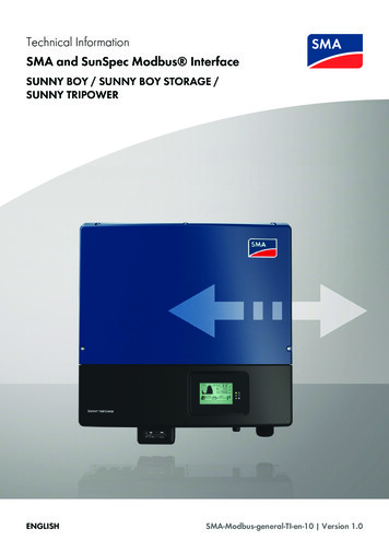
Modbus ProtocolsWe will focus on Modbus Modbus ASCIITCP/IP in this Tutorial Modbus RTU (Remote Terminal Unit)– Modbus RTU uses RS-485 or RS-232 Modbus TCP/IP– Modbus TCP uses EthernetModbus ASCII and Modbus RTU are simple serial protocolsthat use RS-232 or RS-485 to transmit data packets.Modbus TCP/IP follows the OSI Network Model and can beused in an ordinary Ethernet network
Modbus CommunicationRS-232TCP/IPRS-485Multi-drop rSlaveMaster.Slave.128Slave
Modbus TCP/IP Modbus TCP/IP follows the OSI NetworkModel and can be used in an ordinaryEthernet network Modbus TCP requires that you know ordefine IP addresses on the network Modbus TCP/IP uses Port 502
https://www.halvorsen.blogModbus in LabVIEWHans-Petter HalvorsenTable of Contents
Modbus in LabVIEW3 ways to use Modbus in LabVIEW: Use a high-level OPC Server Use Modbus I/O Server Use the LabVIEW Modbus API“LabVIEW Real-Time Module” or “LabVIEWDSC Module” required
LabVIEW Modbus API
https://www.halvorsen.blogLabVIEW ExamplesHans-Petter HalvorsenTable of Contents
Modbus LabVIEW Examples LabVIEW Coils Examples LabVIEW Discrete Input RegistersExamples LabVIEW Input Registers Examples LabVIEW Holding Registers ExamplesMemory TypeData TypeMaster AccessSlave AccessCoilsBit (Boolean)Read/WriteRead/WriteDiscrete InputBit (Boolean)Read-onlyRead/WriteInput RegisterUnsigned WordRead-onlyRead/WriteHolding RegisterUnsigned WordRead/WriteRead/Write
https://www.halvorsen.blogLabVIEW CoilsExamplesHans-Petter HalvorsenTable of Contents
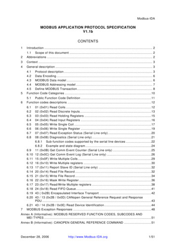
LabVIEW Coils ExampleIn this Example we Create 3 different LabVIEW Applications:LabVIEW App #1LabVIEW App #2Master(Client)Write DataSlave(Server)Polling/RequestMaster(Client)Read DataRegistersData Stored in RegistersLabVIEW App #3Memory TypeCoilsData TypeBit (Boolean)Master AccessRead/WriteSlave AccessRead/Write
LabVIEW Coils ExampleLabVIEW App #2 (Master)Write Data to SlaveLabVIEW App #3 (Master)LabVIEW App #1 (Slave)Read Data from SlaveNote! You need to start/run the Modbus SlaveApp before you start the Modbus Master Apps
Modbus SlaveThis part is just forreading the internal CoilData. It can be removed.It is just to see whennew data from theMasters has beenreceived
Modbus Master (Write)
Modbus Master (Read)
LabVIEW Modbus SimulatorThe LabVIEW Modbus Simulatoris integrated with “LabVIEW RealTime Module” or “LabVIEW DSCModule”It can be used for test purpose,etc.The LabVIEW Modbus Simulator is a Modbus Slave (Server)
NI Example FinderFind ModbusExamples with NIExample Finder
LabVIEW Modbus Simulator Example
https://www.halvorsen.blogLabVIEW Discrete InputRegisters ExamplesHans-Petter HalvorsenTable of Contents
LabVIEW Discrete Input Registers ExamplesIn this Example we Create 2 different LabVIEW Applications:LabVIEW App #1LabVIEW App #2Master(Client)Read DataSlave(Server)RequestRegistersData Stored in RegistersMemory TypeDiscrete InputData TypeBit (Boolean)Master AccessRead-onlySlave AccessRead/Write
LabVIEW Discrete Input Registers Examples
Modbus Slave
Modbus Master
https://www.halvorsen.blogLabVIEW InputRegisters ExamplesHans-Petter HalvorsenTable of Contents
LabVIEW Input Registers ExamplesIn this Example we Create 2 different LabVIEW Applications:LabVIEW App #1LabVIEW App #2Master(Client)Read DataRequestSlave(Server)RegistersData Stored in RegistersMemory TypeInput RegisterData TypeUnsigned WordMaster AccessRead-onlySlave AccessRead/Write
LabVIEW Input Registers Examples
Modbus Slave
Modbus Master Read Input
Decimal/Floating-point NumbersMemory TypeData TypeMaster AccessSlave AccessAn Unsigned Word is a 16-bit nonnegativeInteger Value between 0 – 65535 (2 16) How do you deal with Decimal/Floating-point Numbers? In Modbus, the default practiceis to split a 32-bit floating point value across two 16-bit registers. In this example I just Multiply with 100 in the the Slave Application, then I divide by 100 inthe Master Application, which work when you deal with numbers with 2 decimals, andyou only need one register per number Example: 2.56 2.56x100 256 256/100 2.56Input RegisterUnsigned WordRead-onlyRead/Write
32-bit floating point across two 16-bit registersHere we have split a 32-bit floating point value across two 16-bit registers
32-bit floating point across two 16-bit registersHere we get the 32-bit floating point from two 16-bit registers
https://www.halvorsen.blogLabVIEW HoldingRegisters ExamplesHans-Petter HalvorsenTable of Contents
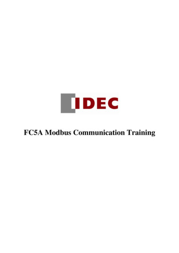
LabVIEW Holding Registers ExampleIn this Example we Create 3 different LabVIEW Applications:LabVIEW App #1LabVIEW App #2Master(Client)Master(Client)Write DataPolling/RequestSlave(Server)Read DataRegistersData Stored in RegistersLabVIEW App #3Memory TypeHolding RegisterData TypeUnsigned WordMaster AccessRead/WriteSlave AccessRead/Write
LabVIEW Holding Registers Example
Modbus Slave
Modbus Master (Write)
Modbus Master (Read)
Alt Solution How do you deal with Decimal/Floating-pointNumbers? Previously we implemented a simple solution bymultiplying and dividing with 100, which worked finefor 2 decimal numbers In Modbus, the default practice is to split a 32-bitfloating point value across two 16-bit registers. The disadvantage is that we need to use 2 Modbusregister for representing one number
32-bit floating point across two 16-bit registersHere we have split a 32-bit floating point value across two 16-bit registers
32-bit floating point across two 16-bit registersHere we get the 32-bit floating point from two 16-bit registers
Modbus Master (Write)
Modbus Master (Read)
Modbus Registers SummaryRegister TypeCoilsDiscrete InputInput RegisterHolding RegisterData TypeBit (Boolean)Bit (Boolean)Unsigned WordUnsigned WordMaster AccessRead/WriteRead-onlyRead-onlyRead/WriteSlave AccessRead/WriteRead/WriteRead/WriteRead/WriteAn Unsigned Word is a 16-bit nonnegative Integer Value between 0 – 65535 (2 16)
References Modbus Organization: http://www.modbus.orgModbus (Wikipedia): https://en.wikipedia.org/wiki/ModbusIntroduction to Modbus (National /Connect LabVIEW to Any PLC With Modbus (National odbus 101 - Introduction to Modbus:http://www.csimn.com/CSI pages/Modbus101.htmlModbus TCP/IP: cpip/Modbus RTU: tu/Using Modbus for Process Control and Automation ng MODBUS for Process Controland Automation.pdf
Hans-Petter HalvorsenUniversity of South-Eastern Norwaywww.usn.noE-mail: hans.p.halvorsen@usn.noWeb: https://www.halvorsen.blog
The LabVIEW Modbus package still use the old terms, so they will also be used in this Tutorial Modbus protocol is defined as a master/slave protocol, meaning a device operating as a . Modbus TCP/IP -Modbus TCP uses Ethernet Modbus ASCII and Modbus RTU are simple serial protocols