Transcription
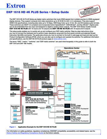
:ANT ompleteORoTm for thuecctions, anedIMP.cinstrng thxtron.eonecti .www stallatieconnGo to uide, in s before er sourcgnowpeuser cificatiothtoetpcsuprodDXP 1616 HD 4K PLUS Series Setup GuideThe DXP 1616 HD 4K PLUS Series are digital matrix switchers that route HDMI signals from multiple sources to HDMI-equippeddisplay devices. They support computer and video resolutions up to 4K @ 60 Hz with 4.4.4 colorspace. They also supportHDMI 2.0b specifications, including data rates up to 18 Gbps, HDR Deep Color up to 12-bit, 3D, and HD lossless audio formats.These switchers are HDCP 2.3 compliant and incorporate Extron SpeedSwitch , EDID Minder , and Key Minder . Digital audiocan be de-embedded from any input and assigned to digital or analog stereo outputs. The DXP 1616 Series models includeDXP 1616 HD 4K PLUS with 16 inputs and 16 outputs and DXP 168 HD 4K PLUS with 16 inputs and 8 outputs.This setup guide enables you to quickly set up and configure your DXP matrix switcher. Step-by-step instructions showyou how to connect the hardware and to perform basic operations using both the front panel controls and selected SimpleInstruction Set (SIS) commands. The guide also shows you how to connect to the built-in web page and load and start up theProduct Configuration Software (PCS), which you can also use to configure and operate the switcher. For additional informationand specifications, see the DXP HD 4K PLUS product page at www.extron.com.The terms “DXP,” “matrix,” “switcher,” and “DXP matrix switcher” are used interchangeably in this guide to refer to both theDXP 1616 and DXP 168 models.Operations CenterAudioExtronFF 220TCeiling SpeakersVideowallHDMIExtronQuantum UltraUltra high Bandwidth 4KVideowall ProcessorHDMIWiFi1 2 3 4CPUsLOCKWiFi1 2 3 4OPENTraffic CamReceiversSTATUSPRIMARY POWERREDUNDANT POWERFRONT FANSREAR FANSQUANTUM ULTRA 610DBS RECEIVERVIDEO WALL PROCESSORDBS RECEIVERExtronXPA 2001-70VPower ES480480p720p 1080i 1080pDIRECTVHDRES480480p720p 1080i 1080pDIRECTVHDSELECT4K ECTVPUSHPOWERGUIDEMENURES480480p720p 1080i PA rationsCenterDXP HD 4K PLUS SERIESDIGITAL CROSSPOINT MATRIX SWITCHERExtronDXP 1616 HD 4K PLUS4K/60 HDMI Matrix Switcherwith Audio De-EmbeddingEthernetHDMIEthernet/PoEIPCP PRO 550COMSWITCHED12 VDC12 LIMIT34 onIPCP Pro 550IP Link ProControl gure 1.ExtronTLP Pro 725M7" Wall MountTouchLink Pro TouchpanelExtronTLP Pro 725M7" Wall MountTouchLink Pro TouchpanelExtronTLP Pro 725M7" Wall MountTouchLink Pro TouchpanelApplication Example for the DXP 1616 HD 4K PLUSFor information on safety guidelines, regulatory compliances, EMI/EMF compatibility, accessibility, and related topics, see theExtron Safety and Regulatory Compliance Guide on the Extron website.1
DXP HD 4K PLUS Series Setup Guide (Continued)Setup StepsFollow these steps to set up and start operating the DXP matrix switcher (see Operation section, beginning on page 6, foradditional setup procedures you may want to perform).1.Turn off power to the input and output devices that will be connected.2.Connect HDMI input devices to the rear panel input connectors (see figure 2, A).3.Connect HDMI audio and video output devices to the rear panel HDMI output connectors (B).4.Connect control devices as desired: Connect a computer or control system to the Remote RS-232 (E) or the front panel USB Config port (see figure 5, A,on page 5). Connect a computer, control system, or network switch to the RJ-45 LAN (Ethernet) port (see figure 2, F).5.Plug the DXP switcher into a grounded AC source, and connect power to the input and output devices.6.Download the PCS program from www.extron.com.7.Select EDID files to apply to inputs as desired, using PCS (see the DXP HD 4K PLUS Help file for details).8.Create ties and presets as desired (see Creating Ties on page 6 and Saving or Recalling a Preset on page 7).Rear Panel ConnectionsMost of the connectors are on the rear panels of the DXP HD 4K PLUS. Figure 2 shows the rear panel of DXP 1616 model.CAUTION:Remove power from the system before making any connections.ATTENTION : Couper l’alimentation avant de faire l’installation électrique.ATTENTION: Use electrostatic discharge precautions (be electrically grounded) when making connections. Electrostatic discharge(ESD) can damage equipment, although you may not feel, see, or hear it. Prenez des précautions contre les décharges électrostatiques (soyez électriquement relié à la terre) lorsque vouseffectuez des connexions. Les décharges électrostatiques (ESD) peuvent endommager l’équipement, même si vous nepouvez pas le sentir, le voir ou 613141516RESETDXP 1616 HD 4K PLUSCBLRRS-232RLAN1.1A MAXAUDIO OUTPUTSOUTPUTSINPUTS100-240VL2REMOTE1S/PDIFTx Rx GA3S/PDIFDEF450-60HzHIABCInput connectorsOutput connectorsReset LEDFigure 2.DEFReset buttonRemote RS-232 connectorLAN portGHIGAnalog audio outputsS/PDIF audio outputsAC power connectorDXP 1616 HD 4K PLUS Rear PanelNOTE: Figure 2 shows the DXP 1616 HD 4K PLUS, with 16 inputs and 16 outputs. The rear panel of the DXP 168 is identicalexcept for the number of outputs.A2Input connectors — Connect HDMI sources to these female 19-pin type A HDMI input connectors for video input.LockIt cable lacing brackets, one for each HDMI input and output connector, are provided with the DXP HD 4K PLUS.These brackets can be used to secure the HDMI cables to the DXP connectors to reduce stress on the HDMI connectorsand prevent signal loss due to loose cable connections (see Securing HDMI Cables with the LockIt HDMI Cable LacingBracket on page 4).
BOutput connectors — Connect HDMI output devices to these female 19-pin type A HDMI output connectors for bufferedvideo output (see Securing HDMI Cables with the LockIt HDMI Cable Lacing Bracket on page 4).CReset LED — While you are holding the Reset button, this green LED blinks every 3 seconds to indicate thelevel of reset that will occur if the button is released at that point (see figure 2, D, on the previous page).DReset button — This recessed button initiates three levels (modes) of reset. Use a pointed object such as a smallscrewdriver to press and hold the Reset button.EF Factory firmware reset (mode 1) — Hold the Reset button while powering up the switcher to restore the DXP tothe factory firmware for a single power cycle. This type of reset maintains all the current user settings, such as audioadjustments, IP settings, and the configuration. IP settings reset (mode 4) — While the DXP is running, press and hold the Reset button until the LED blinks twice(approximately 6 seconds). Release the button and press it again momentarily to reset the switcher IP functions. Thisreset does not replace any user-installed firmware. Absolute reset (mode 5) — While the DXP is running, press and hold the Reset button until the LED blinks three times(approximately 9 seconds). Release the button and press it again momentarily to restore the switcher to the defaultfactory conditions.Remote RS-232 connector — Connect an RS-232 capable hostdevice such as a computer or a touchpanel control to this 3.5 mm3-pole captive screw connector to configure and control theswitcher via SIS commands. Connect the 9-pin end of the RS-232cable to the serial port of your computer or control system. Thedefault port parameters are 9600 baud, 8 data bits, 1 stop bit, noparity.Tx Rx GDXP HD 4K PLUSRear PanelRS-232 PortTx Rx GLAN port — Connect a computer, a network switch, or a controlsystem to this RJ-45 connector. With the Ethernet connection, youcan use a computer to configure and control the networkedswitcher with SIS commands, the PCS configuration program, orthe embedded HTML page.Ethernet connection indicators — The Link and ActLEDs indicate the status of the Ethernet connection.LAN Link — Indicates that the switcher is properlyconnected to an Ethernet LAN. This green LED should lightsteadily. Act (Activity) — Indicates transmission of data on the RJ-45connector. This amber LED should flicker as the switchercommunicates.NOTES: If you use cable that has a drain wire, tiethe drain wire to ground at both ends. Connect a ground wire between the DXPand the computer or control system.Ground (G)Receive (Rx)Transmit (Tx)Transmit (Tx)Receive (Rx)Computer orControl SystemRS-232 PortEthernet links use Category (CAT) 3, 5e, or 6 unshielded twisted pair (UTP) or shielded twisted pair (STP) cables, terminatedwith RJ-45 connectors. Ethernet cables are limited to 328 feet (100 meters).NOTES: Do not use standard telephone cables. Telephone cables do not support Ethernet or Fast Ethernet. Do not stretch or bend the cables because this can cause transmission errors.Crossover CablePins:12345678PinInsert TwistedPair WiresRJ-45ConnectorFigure 3.End 1Wire ColorStraight-through CableEnd 2Wire ColorPinEnd 1Wire ColorEnd 2Wire Color1White-greenWhite-orange1White-orange wnWhite-brown8BrownBrown8BrownBrownT568AT568BA cable that is wired as T568A at one endand T568B at the other (Tx and Rx pairsreversed) is a "crossover" cable.T568BT568BA cable that is wired the same at both endsis called a "straight-through" cable becauseno pin or pair assignments are swapped.Both ends of the cable can be T568B (as shown)or T568A (not shown).RJ-45 Connector and Pinout TablesDefault Ethernet settings: IP address — 192.168.254.254 Subnet mask — 255.255.0.0 Gateway address — 0.0.0.03
DXP HD 4K PLUS Series Setup Guide (Continued)The cable you use depends on your network speed. The switchers support both 10 Mbps (10Base-T — Ethernet) and100 Mbps (100Base-T — Fast Ethernet), half-duplex and full-duplex Ethernet connections. 10Base-T Ethernet requires CAT 3 or higher UTP or STP cables. Fast Ethernet requires CAT 5e or higher UTP or STP cables.Terminate the Ethernet cable as required:G Network connection — Wire as a patch (straight-through) cable. Computer or control system connection — Wire as a crossover cable.Analog audio outputs — Connect powered speakers, an amplifier, or other audio output device to these 5-pole 3.5 mmcaptive screw connectors for 2-ch stereo analog audio output. These connectors can de-embed LPCM audio that was routedfrom any DXP HDMI input and convert it to a stereo analog signal. Figure 4 shows how to wire these connectors. Use thesupplied tie-wrap to strap the audio cable to the extended tail of the connector.No Ground HereLLRTipSleevesTipRTipRingSleevesTipRingNo Ground HereBalanced Audio OutputUnbalanced Audio OutputDo not tin the wires!Figure 4.Connecting Analog AudioATTENTION: For unbalanced audio output, connect the sleeves to the ground contact. DO NOT connect the sleeves to thenegative (-) contacts. Pour l’audio asymétrique, connectez les manchons au contact au sol. Ne PAS connecter les manchons auxcontacts négatifs (–).NOTE:HTip ( )S/PDIF digital audio outputs (Sony/Philips Digital Interface Format) — Use 75 ohm digitalaudio cables to connect audio signal processors (such as the Extron SSP 7.1 Surround SoundProcessor) or other compatible devices to these female RCA connectors (see the illustrationat right). The connected processor then converts digital signals from these ports to analog forencoded standard definition bitstream audio for Dolby or DTS multi-channel surround sound.NOTE:IThe length of exposed wires is important. The ideal length is 3/16 inch (5 mm).Sleeve ( )When the input audio is a high bit rate (HBR) audio stream, mute these outputs.AC power connector — Plug a standard IEC power cord (provided) into this connectorto connect the switcher to a 100 VAC to 240 VAC, 50-60 Hz power source.Securing HDMI Cables with the LockIt HDMI Cable Lacing BracketUse a LockIt HDMI Cable Lacing Bracket to securely fasten each HDMI cable to the switcher:1.Plug the HDMI cable into the panel connection (see the illustration at right, 1).2.Loosen the HDMI connection mounting screw from the panel enough to allow the LockItlacing bracket to be placed over it (2). The screw does not have to be removed.3.Place the LockIt lacing bracket (3) on the screw and against the HDMI connector, thentighten the screw to secure the bracket.321ATTENTION:4 Do not overtighten the HDMI connector mounting screw. The shield it fastens tois thin and can easily be stripped. Ne serrez pas trop la vis de montage du connecteur HDMI. Le blindage auquelelle est attachée est très fin et peut facilement être dénudé.344.Loosely place the included tie wrap around the HDMI connector and the LockIt lacing bracket as shown (4).5.While holding the connector securely against the lacing bracket, use pliers or similar tool to tighten the tie wrap, then removeany excess length.
Front Panel FeaturesThe front panel buttons of the DXP 1616 and DXP 168 are grouped into two sets, with the input and output buttons located onthe left side of the control panel and the control buttons on the right side. The front panel buttons have multiple primary andsecondary functions. For more details on these functions, see the DXP HD 4K PLUS Series User Guide, available at www.extron.com. Each button has an LED beside it. These bicolor LEDs light green when video is selected and red when audio is selected.BCINPUTS12345OUTPUTS67812345679 10 11 12 13 14 15 169 10 11 12 13 14 15 ExtronABCEDADXP HD 4K PLUS SERIESDIGITAL CROSSPOINT MATRIX SWITCHERConfig portInput buttonsDEControl buttonsI/O buttonsOutput buttonsFigure 5.DXP 1616 and DXP 168 HD 4K PLUS Front PanelNOTE: Although the DXP 168 PLUS has 16 output buttons like the DXP 1616 PLUS, only output buttons 1 through 8 arefully functional on the DXP 168. Output buttons 9 through 16 can be used only for creating and recalling presets.AConfig port — This USB mini-B port serves a similar communications function to the rear panel Remote port, but is easierto access than the rear port after the matrix switcher has been installed and cabled. Use a USB type A to mini B cable toconnect this port to a USB connector on the computer to enable SIS commands to be sent from the computer, connection tothe PCS configuration software, and uploading firmware.Front Panel Button FunctionsPrimary FunctionSecondary FunctionsBInput buttons Select an input.Identify the selected input. Save and recall presets.View ties.Select button background lighting.COutput buttons Select outputs.Identify the selected outputs. Save and recall presets.View ties.Mute video and audio.De-embed HDMI audio signals from input.View HDMI audio signals de-embeddedfrom the input.5
DXP HD 4K PLUS Series Setup Guide (Continued)Front Panel Button FunctionsDPrimary FunctionSecondary Functions Save changes made on the front panel.Indicate that a potential tie has beencreated but not saved.Indicate that a global preset has beenselected to be saved or recalled but thepreset action has not been completed. Place the switcher in preset saving modeto save a configuration as a preset, andin preset recalling mode to activate apreviously-defined preset.Indicate when preset saving mode isactive (blinks) and when preset recallingmode is active (lights steadily). Select the baud rate for the RemoteRS-232 port.Place the switcher in view-only mode todisplay the current configuration.Indicate that the DXP is in view-only mode. Select the baud rate for the RemoteRS-232 port.Cancel operations or selections in progress and resets the front panel button indicators.Indicate that the escape function has been activated (blinks once).Select the baud rate for the RemoteRS-232 port.Set the front panel lock modeControl buttonsEnter button Preset button View button Escape button NOTE:I/O buttons (Videoand Audio)— TheVideo button lightsgreen to indicate thatvideo is available forconfiguring or forviewing. The Audiobutton lights red toindicate that audio isavailable.E Select the baud rate for the RemoteRS-232 port.Set the front panel lock mode (executivemode).The Escape button does not reset the current configuration or any presets.Select the signal type, audio or video, forthe input or output.Select audio or video for the configurationthat is being viewed. Select the baud rate for the RemoteRS-232 port.Set the front panel lock mode (executivemode).View the video or audio mute status ofthe selected input or output.Video LED blinks to indicate that the unitis in power save mode.NOTE: In addition, if the unit is in power save mode 1, pressing any of the front panel buttons cancels this mode (see PowerSave Modes on page 8).OperationCreating TiesNOTES:1. "Tie" is an input-to-output connection. "Set of ties" is an input tied to two or more outputs. (An output can never be tied to more than one input.) "Configuration" is one or more ties, one or more sets of ties, or a combination. Audio ties can be made only with de-embedded audio. If power save mode 2 is enabled (all front panel functions are disabled except for mode 1 selection), you cannot use thefront panel to make ties.Press and release the Escape button to clear any input button, output button, or controlbutton indicators that may be lit (or whose LED might be lit).CONTROLENTER6PRESETVIEWESCAPE
2.3.Press and release the Video, Audio, or both I/O buttons to select video,audio, or both.I/OVIDEOPress an input button. The button lights to indicate the selection.Green when video is selectedOff when video is deselectedINPUTS2134567AUDIORed when audio is selectedOff when audio is deselected89 10 11 12 13 14 15 16Figure 6.4.Selecting an Input to be TiedPress the output buttons to which the input is to be tied.Amber indicates a video and audio tie (de-embedded audio outputs 1-4).Green indicates a video-only tie.Red indicates an audio-only tie (de-embedded audio outputs 1-4).OUTPUTS321456789 10 11 12 13 14 15 16Figure 7.5.CONTROLENTERPRESETBlinking green indicates theneed to confirm the change.ESCAPEVIEWSelecting Outputs to be TiedPress the Enter button. All button indicators become unlit.Saving or Recalling a PresetA preset is a complete map of all input and output connections. The current configuration (0) can be saved as a preset in any oneof 16 preset memory slots. Preset locations are assigned to the input and output buttons, and each switcher has as many presetsavailable from the front panel as it has input and output buttons. In addition, all presets can be saved and recalled from the PCSsoftware and by SIS commands. When a preset is retrieved from memory, it becomes the current configuration.Ensure that power save mode 2 (all front panel functions are disabled except for mode 1 selection) is not enabled.NOTE:1.To save a preset, press and hold the Preset button until it blinks.NOTE: The DXP 1616 Series have 16 input buttons. For the purposes of this procedure, the following illustrations showonly the top row of buttons (1 through 8).Press and hold the Presetbutton until it blinks.CONTROLENTERVIEWPRESETESCAPEAssigned Preset2 secondsINPUTSAll buttons with assigned presets light.PRESET12354678Presets not assignedTo recall a preset, press and release the Preset button.Press and release the Preset button.CONTROLENTERPRESETVIEWESCAPEAssigned PresetPreset button lights.INPUTSPRESETAll buttons with assigned presets light.12345678Presets not assignedFigure 8.Saving and Recalling a Preset7
DXP HD 4K PLUS Series Setup Guide (Continued)2.Press the desired input or output button (see the illustration at right).3.Press the Enter button.Press and release the desired input or output button.INPUTS321Power Save Modes65487The button blinks to indicate this preset number isselected to save or recall.Power save modes are selectable only by SIS commands. Three modes areavailable: 0 — Normal (full power) operation (default). 1 — Disables all functions except RS-232, USB, and IP control, andreduces cooling fan speed. This mode is cancelled if power is cycled,any front panel buttons are pressed, PCS is opened, or any SIS commands are sent via RS-232, USB, or IP. 2 — Locks the front panel, reduces cooling fan speed, and disables all functions except RS-232, USB, PCS, and IP control.This mode can be cancelled only by entering the SIS command E 0 PSAV} or opening PCS.CONTROLENTERPRESETVIEWESCAPEThe Enter button blinksto indicate the need toThe green front panel Video LED blinks while the DXP is in power save mode 1 or 2.NOTE:Locking and Unlocking the Front Panel (Executive Mode)The DXP switcher has three levels of security lock that limit the operation of the switcher from the front panel: Lock mode 0 — The front panel is completely unlocked. Lock mode 1 — All front panel functions are locked (except for setting lock mode 2). Some functions can be viewed. Lock mode 2 — Basic functions are unlocked. Advanced functions, such as setting video and audio mute, are locked andcan be viewed only (see the table below). The switcher is shipped from the factory in this mode.Basic FunctionsAdvanced Functions Making ties Saving and recalling presets Changing lock modes Setting video and audio output mutes Setting the RS-232 port baud rateSelecting front panel lock mode 2 or toggling between lock modes 2 and 0NOTES: If the switcher is in lock mode 0 or 1, this procedure selects mode 2. If the switcher is in lock mode 2, this procedure selects mode 0 (unlocksthe switcher).Press and hold Enter, Video, and Audio buttonssimultaneousely to enable lock mode 2 or togglebetween mode 2 and mode 0. Toggle the front panel lock on and off by pressing and holding the Enter,Video, and Audio buttons simultaneously until the following buttons blink twice(approximately 2 seconds). If the DXP is now in lock mode 2, the Escape, Video, and Audio buttonsblink twice.I/OCONTROLENTERPRESETVIEWESCAPEAUDIOVIDEO2 seconds2 secondsI/OCONTROLENTERPRESETVIEWESCAPEVIDEOAUDIOIf the DXP is now in lock mode 0, the Video and Audio buttons blink twice.Selecting front panel lock mode 2 or toggling between lock modes 2 and 1Press and hold Video and Audio buttonssimultaneousely to enable lock mode 2or toggle between mode 1 and mode 2.NOTES: If the switcher is in lock mode 1, this procedure selects mode 2. If the switcher is in lock mode 2, this selects mode 1 (locks all switcher functionsexcept selecting mode 2).I/OToggle the lock on and off by pressing and holding the Video and Audio buttons untilthe following buttons blink twice (approximately 3 seconds). If the DXP is now in lock mode 2, the Escape, Video, and Audio buttons blinktwice.AUDIOVIDEO2 f the DXP is now in lock mode 1, the Video and Audio buttons blink twice.NOTE: To switch from lock mode 1 (the front panel is completely locked) to lock mode 0 (the front panel is unlocked), youmust first switch to mode 2, then from mode 2 to mode 0.8
Viewing TiesSeveral methods are available for viewing which inputs and outputs are actively connected (tie configuration) and which outputsare muted, at the same time.NOTE: Before beginning to view ties and mutes, press the Escape button to clear any pending ties. Ensure the unit is not inpower save mode 2.For the I/O buttons, the Video button routes HDMI signals from any of the inputs to any of the HDMI outputs. The Audio buttonroutes the de-embedded audio from any of the HDMI inputs to any of the S/PDIF and analog audio outputs.1.Press either or both I/O buttons to select audio, video, or both.2.Select the input or output ties to view:To view ties to an input: Press the View button. Output buttons light for outputs that have no ties set. NOTE: If you press an output button while an input is selected for viewing, the output button blinks to indicate apending tie. Press Escape to cancel the tie or Enter to add the tie to the selected input.3. To view ties to an output: Press the desired output button. The buttons for the tied input and all other outputs tied tothat input light. To view all untied outputs: Press View, then press the desired unlit (tied) output button. The buttons for the tied inputand all other outputs tied to that input light.To turn off all lit buttons, press the View or the Escape button, or wait until the lit buttons time out (approximately15 seconds).Muting an Output from the Front PanelNOTES: Mutes are protected when front panel lock mode 2 is selected. You can view the status of the output (muted or unmuted)in lock mode 2 but you cannot change it from the front panel. To enable changes to the mute settings, set the lock mode to 0. Ensure the unit is not in power save mode 2.See Locking and Unlocking the Front Panel (Executive Mode) and Power Save Modes on the previous page for moreinformation.1.Press Escape to clear any button selections or incomplete ties.2.Press the View button.3.Press the Video button, the Audio button, or both to select the signal type to be muted.4.Press the button for the output to be muted, and hold it until it begins to blink (approximately 2 seconds). The buttoncontinues to blink until unmuted.To unmute an output, press and hold the blinking button until the blinking stops (approximately 2 seconds).Viewing the mute configurationYou can view the mute configuration whether the outputs were muted using the front panel, SIS commands, or the PCS software.To view which outputs are currently muted:1.Press the Escape button.2.Press the Video button, the Audio button, or both to select the signal type to be view.3.Press the button for the output to be viewed.If only the audio is mutedIf only the video is muted The output button blinks red. The output button blinks green. The video button lights steadily green. The audio button lights steadily red.If both video and audio are muted, the output button blinks amber.9
DXP HD 4K PLUS Series Setup Guide (Continued)Selecting the Remote RS-232 Port Baud RateNOTES: The serial port baud rate setting is protected when front panel lock mode 2 is selected. You can view the setting in lockmode 2 but you cannot change it from the front panel (see Locking and Unlocking the Front Panel [Executive Mode].) To enable changes to the baud rate setting, set the lock mode to 0. Ensure the unit is not in power save mode 2.To set the baud rate from the front panel:1.Simultaneously press and hold all Control buttons (Enter, Preset, View, and Escape) until all of the Control buttons light(approximately 2 seconds). The Control button representing the current baud rate blinks.2.Press and hold the appropriate Control button until the selected button blinks, to select the desired baud rate:Enter 9600, Preset 19200, View 38400, and Escape 115200.Press and hold all four buttons.CONTROLENTERPRESETFigure 9.VIEWCONTROL2 secoundsESCAPEENTERPRESETVIEWESCAPERS-232 Baud Rate Display3.Release the Control button.4.To exit baud rate selection mode, press and release an output button, or wait for the mode to time out.Remote ControlYou can send SIS commands over an Ethernet link (rear panel RJ-45 LAN port), USB (front panel Config port), or a serialconnection (rear panel Remote RS-232 port). The network connection procedure is described below. For information about theserial and USB connections, as well as a complete list of the available SIS commands, see the DXP HD 4K PLUS Series UserGuide, available at www.extron.com.Establishing a Network (Ethernet) ConnectionTo establish a network connection:1.Open a TCP socket to port 23 using the switcher IP address.NOTE:The factory default IP address is 192.168.254.254.The switcher responds with a message consisting of the copyright date, the name of the product, firmware version, partnumber, and the current date and time. For example, with an internet connection:(c) Copyright 20nn, Extron Electronics, DXP nnn HD 4K Plus, Vn.nn, 60-nnnn-21 ]Ddd, DD Mmm YYYY HH:MM:SS ]NOTES:2. If the switcher is not password-protected, the device is now ready to accept SIS commands. If the switcher is password-protected, a password prompt appears.If the switcher is password-protected, enter the password.NOTE: The factory configured passwords for all accounts on this device have been set to the device serial number. Inthe event of an absolute system reset, the passwords convert to the default, which is no password.3.If the password is accepted, the switcher responds with Login User or Login Administrator.If the password is not accepted, the Password prompt reappears (see your network administrator for the assigned password).Connection timeoutsThe Ethernet link times out and disconnects after a designated period of no communications. By default, this timeout value is setto 5 minutes but the value can be changed.NOTE: Extron recommends leaving the default timeout at 5 minutes and periodically issuing the Query (Q) command to keepthe connection active or disconnecting the socket and reopening the connection when necessary.10
Number of connectionsA DXP switcher can have up to 200 simultaneous TCP connections, including all HTTP sockets and Telnet connections. Whenthe connection limit is reached, the switcher accepts no new connections until some have been closed. No error message orindication is given that the connection limit has been reached. To maximize performance of your switcher, keep the number ofconnections low and close unnecessary open sockets.Command and Response Table for SIS CommandsThe switchers have SIS commands that you can use for operation and configuration. You can issue these commands froma PC connected to the DXP serial port, USB port, or Ethernet port
The terms "DXP," "matrix," "switcher," and "DXP matrix switcher" are used interchangeably in this guide to refer to both the DXP 1616 and DXP 168 models. WiFi 1234 WiFi 1 234 DBS RECEIVER DBS RECEIVER PUSH PUSH POWER GUIDE MENU RES 480 480p 720p 1080i 1080p DIRECTV HD SELECT DIRECT V PUSH PUSH