Transcription
Modbus LabVIEW Library HelpFebruary 2009, 372767A-01This help file describes the Modbus LabVIEW VI library.For more information about this help file, refer to the following topics:Using HelpImportant InformationTechnical Support and Professional ServicesTo comment on National Instruments documentation, refer to the NationalInstruments Web site. 2009 National Instruments Corporation. All rights reserved.
Using HelpConventionsNavigating HelpSearching HelpPrinting Help File Topics
ConventionsThis help file uses the following formatting and typographicalconventions:This icon denotes a note, which alerts you to importantinformation.This icon denotes a tip, which alerts you to advisoryinformation.boldBold text denotes items that you must select or click in thesoftware, such as menu items and dialog box options. Boldtext also denotes parameter names.greenUnderlined text in this color denotes a link to a help topic,help file, or Web address.purpleUnderlined text in this color denotes a visited link to a helptopic, help file, or Web address.italicItalic text denotes variables, emphasis, cross-references, oran introduction to a key concept. Italic text also denotes textthat is a placeholder for a word or value that you mustsupply.monospace Text in this font denotes text or characters that you shouldenter from the keyboard, sections of code, programmingexamples, and syntax examples. This font is also used forthe proper names of disk drives, paths, directories,programs, subprograms, subroutines, device names,functions, operations, variables, filenames, and extensions.
Navigating Help (Windows Only)To navigate this help file, use the Contents, Index, and Search tabs tothe left of this window or use the following toolbar buttons located abovethe tabs:Note The information in this topic only applies to the help fileinstalled with the Windows version of the software.Hide—Hides the navigation pane from view.Locate—Locates the currently displayed topic in the Contentstab, allowing you to view related topics.Back—Displays the previously viewed topic.Forward—Displays the topic you viewed before clicking theBack button.Options—Displays a list of commands and viewing options forthe help file.
Searching Help (Windows Only)Use the Search tab to the left of this window to locate content in this helpfile.Note The information in this topic only applies to the help fileinstalled with the Windows version of the software.If you want to search for words in a certain order, such as "relateddocumentation," add quotation marks around the search words as shownin the example. Searching for terms on the Search tab allows you toquickly locate specific information and information in topics that are notincluded on the Contents tab.Tip You can temporarily disable the search highlighting feature byselecting Options»Search Highlight Off from the toolbar.
WildcardsYou also can search using asterisk (*) or question mark (?) wildcards.Use the asterisk wildcard to return topics that contain a certain string. Forexample, a search for "prog*" lists topics that contain the words"program," "programmatically," "progress," and so on.Use the question mark wildcard as a substitute for a single character in asearch term. For example, "?ext" lists topics that contain the words"next," "text," and so on.Note Wildcard searching will not work on Simplified Chinese,Traditional Chinese, Japanese, and Korean systems.
Nested ExpressionsUse nested expressions to combine searches to further refine a search.You can use Boolean expressions and wildcards in a nested expression.For example, "example AND (program OR VI)" lists topics that contain"example program" or "example VI." You cannot nest expressions morethan five levels.
Boolean ExpressionsClick the button to add Boolean expressions to a search. The followingBoolean operators are available:AND (default)—Returns topics that contain both search terms.You do not need to specify this operator unless you are usingnested expressions.OR—Returns topics that contain either the first or second term.NOT—Returns topics that contain the first term without thesecond term.NEAR—Returns topics that contain both terms within eight wordsof each other.
Search OptionsUse the following checkboxes on the Search tab to customize a search:Search previous results—Narrows the results from a searchthat returned too many topics. You must remove the checkmarkfrom this checkbox to search all topics.Match similar words—Broadens a search to return topics thatcontain words similar to the search terms. For example, a searchfor "program" lists topics that include the words "programs,""programming," and so on.Search titles only—Searches only in the titles of topics.
Printing Help File Topics (Windows Only)Complete the following steps to print an entire book from the Contentstab:Note The information in this topic only applies to the help fileinstalled with the Windows version of the software.1. Right-click the book.2. Select Print from the shortcut menu to display the Print Topicsdialog box.3. Select the Print the selected heading and all subtopics option.Note Select Print the selected topic if you want to printthe single topic you have selected in the Contents tab.4. Click the OK button.
Printing PDF DocumentsThis help file may contain links to PDF documents. To print PDFdocuments, click the print button located on the Adobe Acrobat Viewertoolbar.
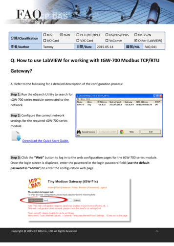
MB Ethernet Master Query Read Coils (poly).viThe master uses this VI read the slaves' coils. This corresponds to apublic function code of 1 in the MODBUS protocol.MBAP Header is a cluster containing the transaction ID and UnitID. This is additional information not usually required for aMODBUS transaction.Transaction Identifier—This identifier is for transaction pairing;the MODBUS server copies the request transaction identifier inthe response.Unit Identifier—This field is for intra-system routing purposes. Ittypically communicates to a MODBUS serial line slave through agateway between an Ethernet TCP-IP network and a MODBUSserial line. The MODBUS client sets this field in the request, andthe server response must return this field with the same value.TCP Connection Refnum in is a network connection refnum thatuniquely identifies the TCP connection. Use TCP OpenConnection.vi to open a TCP connection.Starting Address is the first address location of the coil to read.This address is sometimes referred to as offset. Refer to yourdevice's documentation to find the coil address mapping.Be sure to specify the correct address in the MODBUS deviceconfiguration software for the register you want to use in LabVIEW.In most MODBUS device configuration software, you must enter aname for the register you want to use. Per MODBUS convention,the register address of the slave device is calculated bysubtracting 1 from the register name that you specify in the masterdevice configuration software. The MODBUS LabVIEW libraryexpects register addresses, not register names, so you may needto subtract 1 from the address you defined in the MODBUS device
configuration software. For example, a register name defined as 2in a MODBUS configuration device translates to register address 1in the Holding Registers table of the LabVIEW MODBUS library, asshown below.MODBUS Holding Register Name 2DeviceLabVIEWHolding Register Address 1Quantity represents how many coils to read from the slave. The VIreturns the coil at Starting Address and each following coil up toQuantity. For example, if Starting Address is 0 and Quantity is4, the VI reads coils from the slave at address 0, 1, 2, and 3.Timeout specifies the maximum time period, in milliseconds, thatthe VI waits for the slave's response before throwing an error.error in describes error conditions that occur before this VI orfunction runs. The default is no error. If an error occurred beforethis VI or function runs, the VI or function passes the error in valueto error out. If an error occurs while this VI or function runs, the VIor function runs normally and sets its own error status in error out.Use the Simple Error Handler or General Error Handler VIs todisplay the description of the error code. Use error in and errorout to check errors and to specify execution order by wiring errorout from one node to error in of the next node.status is TRUE (X) if an error occurred before this VI orfunction ran or FALSE (checkmark) to indicate a warning orthat no error occurred before this VI or function ran. Thedefault is FALSE.code is the error or warning code. The default is 0. If statusis TRUE, code is a negative error code. If status is FALSE,code is 0 or a warning code.source identifies where an error occurred. The sourcestring includes the name of the VI that produced the error,what inputs are in error, and how to eliminate the error.TCP Connection Refnum (dup) can be an input to anotherMODBUS VI, or you can close it using TCP Close Connection.vi.Coils represents the data read from the slave.
Exception Code is nonzero if a MODBUS error has occurred. Theexception code mapping is as follows:0 No error1 Illegal function2 Illegal data address3 Illegal data value4 Failure in associated device5 Acknowledge6 Busy, rejected message7 NAK—Negative acknowledgeFor more information about these error codes, refer to yourdevice's documentation.error out contains error information. If error in indicates that anerror occurred before this VI or function ran, error out contains thesame error information. Otherwise, it describes the error statusthat this VI or function produces. Right-click the error out frontpanel indicator and select Explain Error from the shortcut menufor more information about the error.status is TRUE (X) if an error occurred or FALSE(checkmark) to indicate a warning or that no error occurred.code is the error or warning code. If status is TRUE, codeis a nonzero error code. If status is FALSE, code is 0 or awarning code.source describes the origin of the error or warning and is, inmost cases, the name of the VI or function that producedthe error or warning.
MB Ethernet Master Query Read Discrete Inputs(poly).viThe master uses this VI to read the slaves' discrete inputs. Thiscorresponds to a public function code of 2 in the MODBUS protocol.MBAP Header is a cluster containing the transaction ID and UnitID. This is additional information not usually required for aMODBUS transaction.Transaction Identifier—This identifier is for transaction pairing;the MODBUS server copies the request transaction identifier inthe response.Unit Identifier—This field is for intra-system routing purposes. Ittypically communicates to a MODBUS serial line slave through agateway between an Ethernet TCP-IP network and a MODBUSserial line. The MODBUS client sets this field in the request, andthe server response must return this field with the same value.TCP Connection Refnum in is a network connection refnum thatuniquely identifies the TCP connection. Use TCP OpenConnection.vi to open a TCP connection.Starting Address is the first address location of the discreteinputs to read. This address is sometimes referred to as offset.Refer to your device's documentation to find the discrete inputaddress mapping.Be sure to specify the correct address in the MODBUS deviceconfiguration software for the register you want to use in LabVIEW.In most MODBUS device configuration software, you must enter aname for the register you want to use. Per MODBUS convention,the register address of the slave device is calculated bysubtracting 1 from the register name that you specify in the masterdevice configuration software. The MODBUS LabVIEW library
expects register addresses, not register names, so you may needto subtract 1 from the address you defined in the MODBUS deviceconfiguration software. For example, a register name defined as 2in a MODBUS configuration device translates to register address 1in the Holding Registers table of the LabVIEW MODBUS library, asshown below.MODBUS Holding Register Name 2DeviceLabVIEWHolding Register Address 1Quantity represents how many discrete inputs to read from theslave. The VI returns the discrete input at Starting Address andeach following discrete input up to Quantity. For example, ifStarting Address is 0 and Quantity is 4, the VI reads discreteinputs from the slave at address 0, 1, 2, and 3.Timeout specifies the maximum time period, in milliseconds, thatthe VI waits for the slave's response before throwing an error.error in describes error conditions that occur before this VI orfunction runs. The default is no error. If an error occurred beforethis VI or function runs, the VI or function passes the error in valueto error out. If an error occurs while this VI or function runs, the VIor function runs normally and sets its own error status in error out.Use the Simple Error Handler or General Error Handler VIs todisplay the description of the error code. Use error in and errorout to check errors and to specify execution order by wiring errorout from one node to error in of the next node.status is TRUE (X) if an error occurred before this VI orfunction ran or FALSE (checkmark) to indicate a warning orthat no error occurred before this VI or function ran. Thedefault is FALSE.code is the error or warning code. The default is 0. If statusis TRUE, code is a negative error code. If status is FALSE,code is 0 or a warning code.source identifies where an error occurred. The sourcestring includes the name of the VI that produced the error,what inputs are in error, and how to eliminate the error.
TCP Connection Refnum (dup) can be an input to anotherMODBUS VI, or you can close it using TCP Close Connection.vi.Discrete Inputs represents the data read from the slave.Exception Code is nonzero if a MODBUS error has occurred. Theexception code mapping is as follows:0 No error1 Illegal function2 Illegal data address3 Illegal data value4 Failure in associated device5 Acknowledge6 Busy, rejected message7 NAK—Negative acknowledgeFor more information about these error codes, refer to yourdevice's documentation.error out contains error information. If error in indicates that anerror occurred before this VI or function ran, error out contains thesame error information. Otherwise, it describes the error statusthat this VI or function produces. Right-click the error out frontpanel indicator and select Explain Error from the shortcut menufor more information about the error.status is TRUE (X) if an error occurred or FALSE(checkmark) to indicate a warning or that no error occurred.code is the error or warning code. If status is TRUE, codeis a nonzero error code. If status is FALSE, code is 0 or awarning code.source describes the origin of the error or warning and is, inmost cases, the name of the VI or function that producedthe error or warning.
MB Ethernet Master Query Read ExceptionStatus (poly).viThe master uses this VI to read the exception status from the slave. Thiscorresponds to a public function code of 7 in the MODBUS protocol.MBAP Header is a cluster containing the transaction ID and UnitID. This is additional information not usually required for aMODBUS transaction.Transaction Identifier—This identifier is for transaction pairing;the MODBUS server copies the request transaction identifier inthe response.Unit Identifier—This field is for intra-system routing purposes. Ittypically communicates to a MODBUS serial line slave through agateway between an Ethernet TCP-IP network and a MODBUSserial line. The MODBUS client sets this field in the request, andthe server response must return this field with the same value.TCP Connection Refnum in is a network connection refnum thatuniquely identifies the TCP connection. Use TCP OpenConnection.vi to open a TCP connection.Timeout specifies the maximum time period, in milliseconds, thatthe VI waits for the slave's response before throwing an error.error in describes error conditions that occur before this VI orfunction runs. The default is no error. If an error occurred beforethis VI or function runs, the VI or function passes the error in valueto error out. If an error occurs while this VI or function runs, the VIor function runs normally and sets its own error status in error out.Use the Simple Error Handler or General Error Handler VIs todisplay the description of the error code. Use error in and errorout to check errors and to specify execution order by wiring errorout from one node to error in of the next node.status is TRUE (X) if an error occurred before this VI or
function ran or FALSE (checkmark) to indicate a warning orthat no error occurred before this VI or function ran. Thedefault is FALSE.code is the error or warning code. The default is 0. If statusis TRUE, code is a negative error code. If status is FALSE,code is 0 or a warning code.source identifies where an error occurred. The sourcestring includes the name of the VI that produced the error,what inputs are in error, and how to eliminate the error.TCP Connection Refnum (dup) can be an input to anotherMODBUS VI, or you can close it using TCP Close Connection.vi.Exception Code is nonzero if a MODBUS error has occurred. Theexception code mapping is as follows:0 No error1 Illegal function2 Illegal data address3 Illegal data value4 Failure in associated device5 Acknowledge6 Busy, rejected message7 NAK—Negative acknowledgeFor more information about these error codes, refer to yourdevice's documentation.error out contains error information. If error in indicates that anerror occurred before this VI or function ran, error out contains thesame error information. Otherwise, it describes the error statusthat this VI or function produces. Right-click the error out frontpanel indicator and select Explain Error from the shortcut menufor more information about the error.status is TRUE (X) if an error occurred or FALSE(checkmark) to indicate a warning or that no error occurred.code is the error or warning code. If status is TRUE, codeis a nonzero error code. If status is FALSE, code is 0 or a
warning code.source describes the origin of the error or warning and is, inmost cases, the name of the VI or function that producedthe error or warning.
MB Ethernet Master Query Read HoldingRegisters (poly).viThe master uses this VI to read the slaves' holding registers. Thiscorresponds to a public function code of 3 in the MODBUS protocol.MBAP Header is a cluster containing the transaction ID and UnitID. This is additional information not usually required for aMODBUS transaction.Transaction Identifier—This identifier is for transaction pairing;the MODBUS server copies the request transaction identifier inthe response.Unit Identifier—This field is for intra-system routing purposes. Ittypically communicates to a MODBUS serial line slave through agateway between an Ethernet TCP-IP network and a MODBUSserial line. The MODBUS client sets this field in the request, andthe server response must return this field with the same value.TCP Connection Refnum in is a network connection refnum thatuniquely identifies the TCP connection. Use TCP OpenConnection.vi to open a TCP connection.Starting Address is the first address location of the holdingregister to read. This address is sometimes referred to as offset.Refer to your device's documentation to find the holding registeraddress mapping.Be sure to specify the correct address in the MODBUS deviceconfiguration software for the register you want to use in LabVIEW.In most MODBUS device configuration software, you must enter aname for the register you want to use. Per MODBUS convention,the register address of the slave device is calculated bysubtracting 1 from the register name that you specify in the masterdevice configuration software. The MODBUS LabVIEW library
expects register addresses, not register names, so you may needto subtract 1 from the address you defined in the MODBUS deviceconfiguration software. For example, a register name defined as 2in a MODBUS configuration device translates to register address 1in the Holding Registers table of the LabVIEW MODBUS library, asshown below.MODBUS Holding Register Name 2DeviceLabVIEWHolding Register Address 1Quantity represents how many holding registers to read from theslave. The VI returns the holding register at Starting Address andeach following holding register up to Quantity. For example, ifStarting Address is 0 and Quantity is 4, the VI reads holdingregisters from the slave at address 0, 1, 2, and 3.Timeout specifies the maximum time period, in milliseconds, thatthe VI waits for the slave's response before throwing an error.error in describes error conditions that occur before this VI orfunction runs. The default is no error. If an error occurred beforethis VI or function runs, the VI or function passes the error in valueto error out. If an error occurs while this VI or function runs, the VIor function runs normally and sets its own error status in error out.Use the Simple Error Handler or General Error Handler VIs todisplay the description of the error code. Use error in and errorout to check errors and to specify execution order by wiring errorout from one node to error in of the next node.status is TRUE (X) if an error occurred before this VI orfunction ran or FALSE (checkmark) to indicate a warning orthat no error occurred before this VI or function ran. Thedefault is FALSE.code is the error or warning code. The default is 0. If statusis TRUE, code is a negative error code. If status is FALSE,code is 0 or a warning code.source identifies where an error occurred. The sourcestring includes the name of the VI that produced the error,what inputs are in error, and how to eliminate the error.
TCP Connection Refnum (dup) can be an input to anotherMODBUS VI, or you can close it using TCP Close Connection.vi.Holding Registers represents the data read from the slave.Exception Code is nonzero if a MODBUS error has occurred. Theexception code mapping is as follows:0 No error1 Illegal function2 Illegal data address3 Illegal data value4 Failure in associated device5 Acknowledge6 Busy, rejected message7 NAK—Negative acknowledgeFor more information about these error codes, refer to yourdevice's documentation.error out contains error information. If error in indicates that anerror occurred before this VI or function ran, error out contains thesame error information. Otherwise, it describes the error statusthat this VI or function produces. Right-click the error out frontpanel indicator and select Explain Error from the shortcut menufor more information about the error.status is TRUE (X) if an error occurred or FALSE(checkmark) to indicate a warning or that no error occurred.code is the error or warning code. If status is TRUE, codeis a nonzero error code. If status is FALSE, code is 0 or awarning code.source describes the origin of the error or warning and is, inmost cases, the name of the VI or function that producedthe error or warning.
MB Ethernet Master Query Read Input Registers(poly).viThe master uses this VI to read the slaves' input registers. Thiscorresponds to a public function code of 4 in the MODBUS protocol.MBAP Header is a cluster containing the transaction ID and UnitID. This is additional information not usually required for aMODBUS transaction.Transaction Identifier—This identifier is for transaction pairing;the MODBUS server copies the request transaction identifier inthe response.Unit Identifier—This field is for intra-system routing purposes. Ittypically communicates to a MODBUS serial line slave through agateway between an Ethernet TCP-IP network and a MODBUSserial line. The MODBUS client sets this field in the request, andthe server response must return this field with the same value.TCP Connection Refnum in is a network connection refnum thatuniquely identifies the TCP connection. Use TCP OpenConnection.vi to open a TCP connection.Starting Address is the first address location of the input registerto read. This address is sometimes referred to as offset. Refer toyour device's documentation to find the input register addressmapping.Be sure to specify the correct address in the MODBUS deviceconfiguration software for the register you want to use in LabVIEW.In most MODBUS device configuration software, you must enter aname for the register you want to use. Per MODBUS convention,the register address of the slave device is calculated bysubtracting 1 from the register name that you specify in the masterdevice configuration software. The MODBUS LabVIEW library
expects register addresses, not register names, so you may needto subtract 1 from the address you defined in the MODBUS deviceconfiguration software. For example, a register name defined as 2in a MODBUS configuration device translates to register address 1in the Holding Registers table of the LabVIEW MODBUS library, asshown below.MODBUS Holding Register Name 2DeviceLabVIEWHolding Register Address 1Quantity represents how many input registers to read from theslave. The VI returns the input register at Starting Address andeach following input register up to Quantity. For example, ifStarting Address is 0 and Quantity is 4, the VI reads inputregisters from the slave at address 0, 1, 2, and 3.Timeout specifies the maximum time period, in milliseconds, thatthe VI waits for the slave's response before throwing an error.error in describes error conditions that occur before this VI orfunction runs. The default is no error. If an error occurred beforethis VI or function runs, the VI or function passes the error in valueto error out. If an error occurs while this VI or function runs, the VIor function runs normally and sets its own error status in error out.Use the Simple Error Handler or General Error Handler VIs todisplay the description of the error code. Use error in and errorout to check errors and to specify execution order by wiring errorout from one node to error in of the next node.status is TRUE (X) if an error occurred before this VI orfunction ran or FALSE (checkmark) to indicate a warning orthat no error occurred before this VI or function ran. Thedefault is FALSE.code is the error or warning code. The default is 0. If statusis TRUE, code is a negative error code. If status is FALSE,code is 0 or a warning code.source identifies where an error occurred. The sourcestring includes the name of the VI that produced the error,what inputs are in error, and how to eliminate the error.
TCP Connection Refnum (dup) can be an input to anotherMODBUS VI, or you can close it using TCP Close Connection.vi.Input Registers represents the data read from the slave.Exception Code is nonzero if a MODBUS error has occurred. Theexception code mapping is as follows:0 No error1 Illegal function2 Illegal data address3 Illegal data value4 Failure in associated device5 Acknowledge6 Busy, rejected message7 NAK—Negative acknowledgeFor more information about these error codes, refer to yourdevice's documentation.error out contains error information. If error in indicates that anerror occurred before this VI or function ran, error out contains thesame error information. Otherwise, it describes the error statusthat this VI or function produces. Right-click the error out frontpanel indicator and select Explain Error from the shortcut menufor more information about the error.status is TRUE (X) if an error occurred or FALSE(checkmark) to indicate a warning or that no error occurred.code is the error or warning code. If status is TRUE, codeis a nonzero error code. If status is FALSE, code is 0 or awarning code.source describes the origin of the error or warning and is, inmost cases, the name of the VI or function that producedthe error or warning.
MB Ethernet Master Query Write Multiple Coils(poly).viThe master uses this VI to write multiple coils to the slave. Thiscorresponds to a public function code of 15 in the MODBUS protocol.MBAP Header is a cluster containing the transaction ID and UnitID. This is additional information not usually required for aMODBUS transaction.Transaction Identifier—This identifier is for transaction pairing;the MODBUS server copies the request transaction identifier inthe response.Unit Identifier—This field is for intra-system routing purposes. Ittypically communicates to a MODBUS serial line slave through agateway between an Ethernet TCP-IP network and a MODBUSserial line. The MODBUS client sets this field in the request, andthe server response must return this field with the same value.TCP Connection Refnum in is a network connection refnum thatuniquely identifies the TCP connection. Use TCP OpenConnection.vi to open a TCP connection.Starting Address is the address location of the first coil to write.This address is sometimes referred to as offset. Refer to yourdevice's documentation to find the coil address mapping.Be sure to specify the correct address in the MODBUS deviceconfiguration software for the register you want to use in LabVIEW.In most MODBUS device configuration software, you must enter aname for the register you want to use. Per MODBUS convention,the register address of the slave device is calculated bysubtracting 1 from the register name that you specify in the masterdevice configuration software. The MODBUS LabVIEW libraryexpects register addresses, not register names, so you may need
to subtract 1 from the address you defined in the MODBUS deviceconfiguration software. For example, a register name defined as 2in a MODBUS configuration device translates to register address 1in the Holding Registers table of the LabVIEW MODBUS library, asshown below.MODBUS Holding Register Name 2DeviceLabVIEWHolding Register Address 1Coils is the coils to write. The array length represents the numberof coils that will be written.Timeout specifies the maximum time period, in milliseconds, thatthe VI waits for the slave's response before throwing an error.error in describes er
typically communicates to a MODBUS serial line slave through a gateway between an Ethernet TCP-IP network and a MODBUS serial line. The MODBUS client sets this field in the request, and the server response must return this field with the same value. TCP Connection Refnum in is a network connection refnum that uniquely identifies the TCP connection.
